
Single Phase System RL parallel circuit IR IL








- Slides: 28
Single Phase System
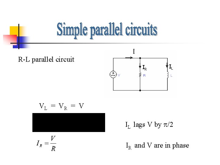
R-L parallel circuit IR IL VL = V R = V IL lags V by /2 IR and V are in phase
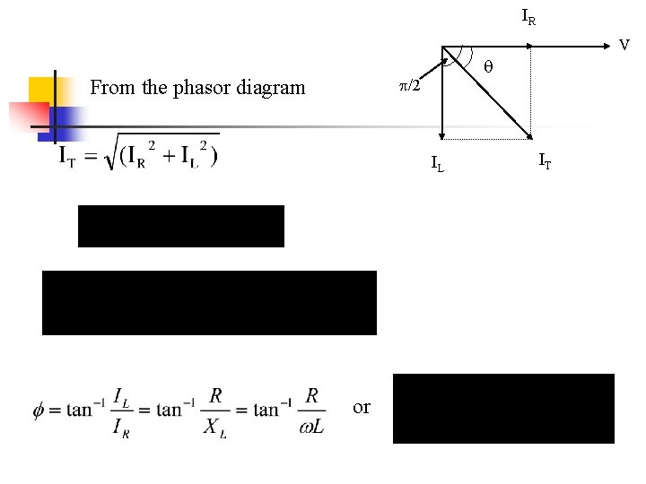
IR V /2 From the phasor diagram IL or IT
Admittance triangle For parallel circuit we look at admittance G V - /2 BL = tan-1 (BL/G) = tan-1 (1/ LG) cos = G/Y = Z/R Power factor Y
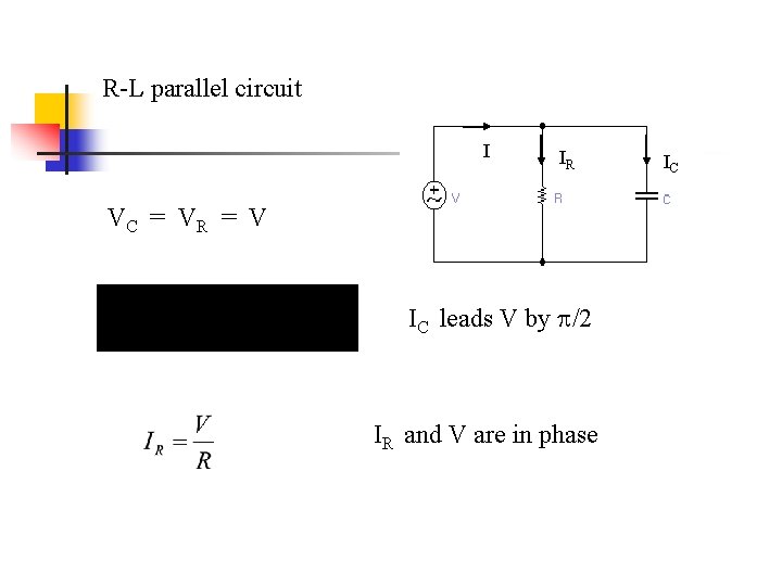
R-L parallel circuit I IR VC = V R = V IC leads V by /2 IR and V are in phase IC
IC IT From the phasor diagram /2 V IR Admittance. G triangle - /2 = tan-1 (BC/G) = tan-1 ( C/G) cos = G/Y = Z/R power factor BL Y V
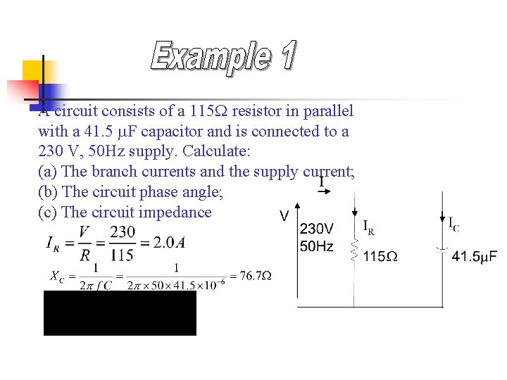
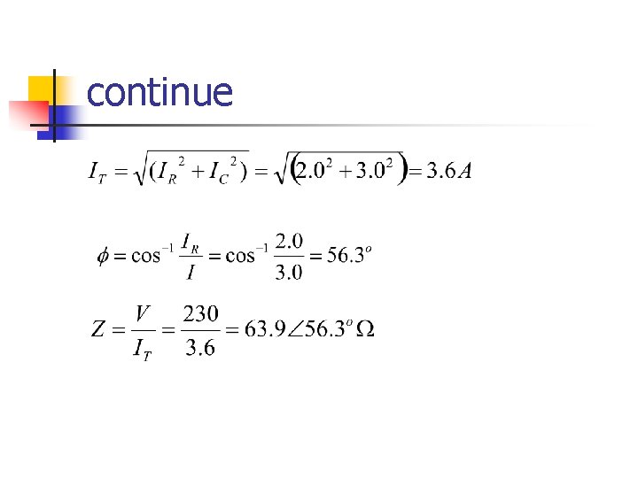
A circuit consists of a 115 resistor in parallel with a 41. 5 m. F capacitor and is connected to a 230 V, 50 Hz supply. Calculate: (a) The branch currents and the supply current; (b) The circuit phase angle; (c) The circuit impedance
continue
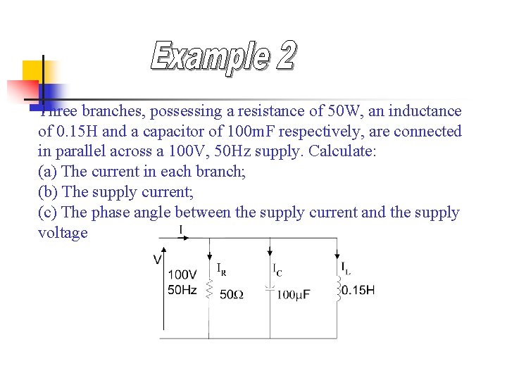
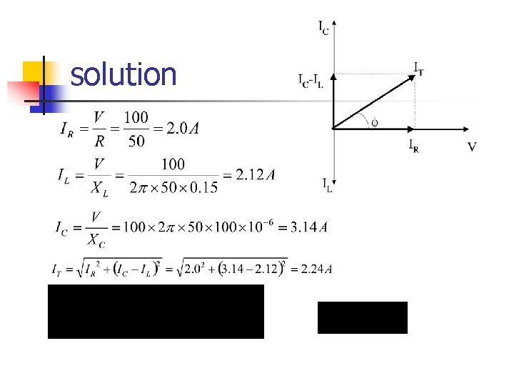
Three branches, possessing a resistance of 50 W, an inductance of 0. 15 H and a capacitor of 100 m. F respectively, are connected in parallel across a 100 V, 50 Hz supply. Calculate: (a) The current in each branch; (b) The supply current; (c) The phase angle between the supply current and the supply voltage
solution
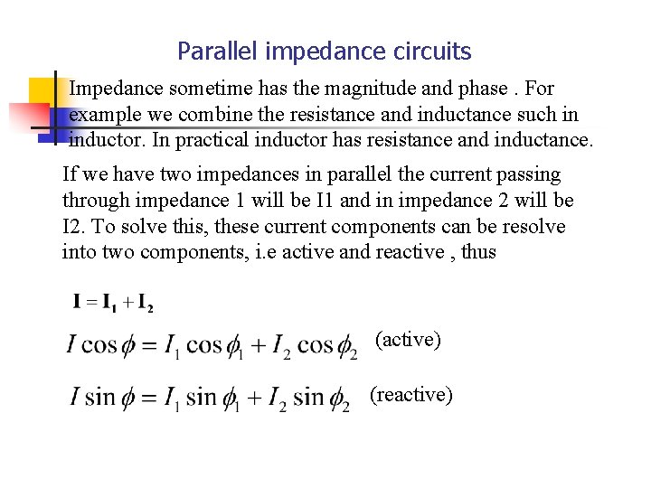
Parallel impedance circuits Impedance sometime has the magnitude and phase. For example we combine the resistance and inductance such in inductor. In practical inductor has resistance and inductance. If we have two impedances in parallel the current passing through impedance 1 will be I 1 and in impedance 2 will be I 2. To solve this, these current components can be resolve into two components, i. e active and reactive , thus (active) (reactive)
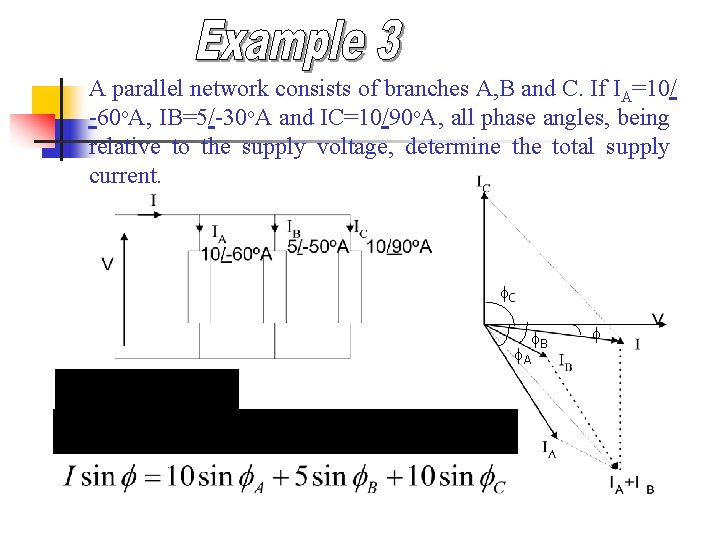
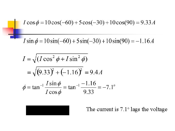
A parallel network consists of branches A, B and C. If IA=10/ -60 o. A, IB=5/-30 o. A and IC=10/90 o. A, all phase angles, being relative to the supply voltage, determine the total supply current. f. C f. A f. B f
The current is 7. 1 o lags the voltage
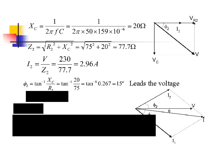
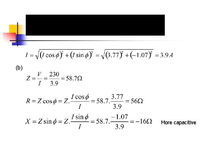
A coil of resistance 50 W and inductance 0. 318 H is connected in parallel with a circuit comprising a 75 W resistor in series with a 159 m. F capacitor. The resulting circuit is connected to a 230 V, 50 Hz a. c supply. Calculate: (a) the supply current; (b) the circuit impedance; resistance and reactance. Lags the voltage
Leads the voltage
(b) More capacitive
Resonance circuits
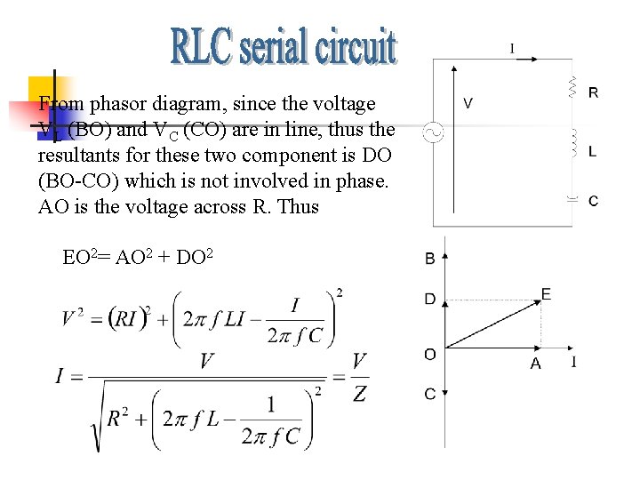
From phasor diagram, since the voltage VL (BO) and VC (CO) are in line, thus the resultants for these two component is DO (BO-CO) which is not involved in phase. AO is the voltage across R. Thus EO 2= AO 2 + DO 2
Therefore the impedance is When resonance or and Z=R therefore I=V/R ; f =0
Current (I) and impedance (Z) vs frequensi (f) in R, L & C serial circuit Z [ ] I [A] Z R I 0 fr f [Hz]
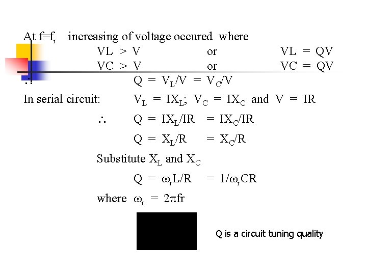
At f=fr increasing of voltage occured where VL > V or VC > V or Q = VL/V = VC/V In serial circuit: VL = QV VC = QV VL = IXL; VC = IXC and V = IR Q = IXL/IR = IXC/IR Q = XL/R = XC/R Substitute XL and XC Q = r. L/R = 1/ r. CR where r = 2 fr Q is a circuit tuning quality
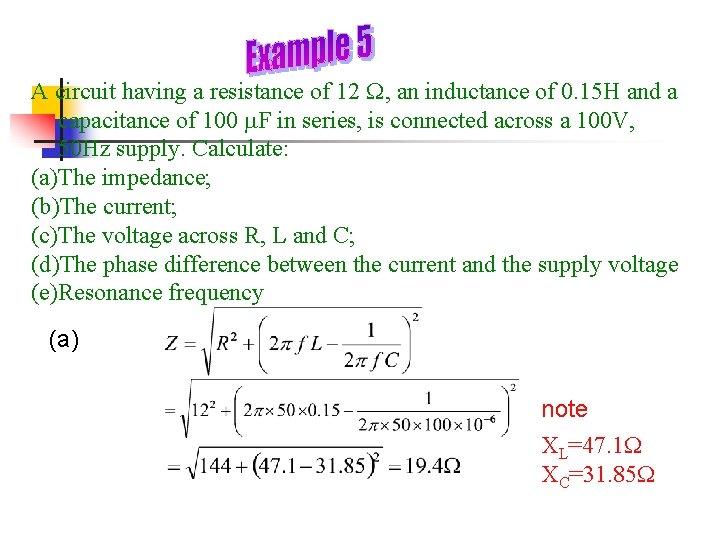
A circuit having a resistance of 12 , an inductance of 0. 15 H and a capacitance of 100 m. F in series, is connected across a 100 V, 50 Hz supply. Calculate: (a)The impedance; (b)The current; (c)The voltage across R, L and C; (d)The phase difference between the current and the supply voltage (e)Resonance frequency (a) note XL=47. 1 XC=31. 85
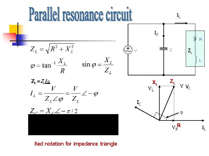
IL IC ZL ZL=ZL/ XL VL ZL V VC IC VRR Red notation for impedance triangle IL
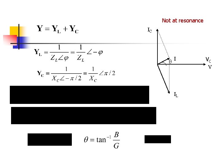
Not at resonance IC I IL VC V
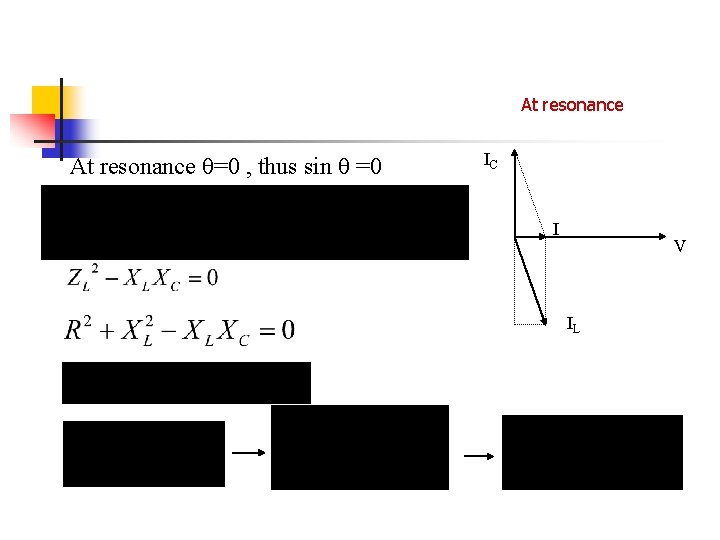
At resonance =0 , thus sin =0 IC I V IL
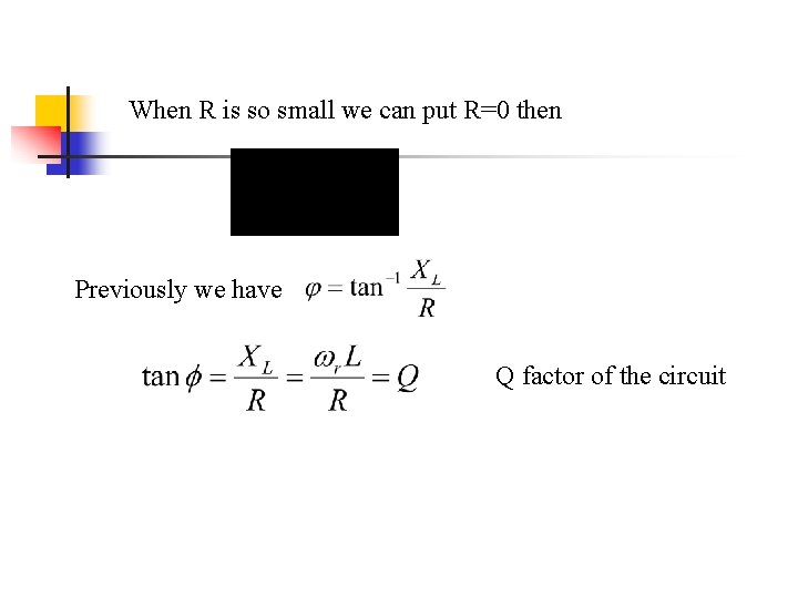
When R is so small we can put R=0 then Previously we have Q factor of the circuit