SIMULATION OF SEMIACTIVE SUSPENSION OF QUARTER CAR MODEL


, semi-active")


 Control Method � The absolute acceleration of the mass based")


 vs.")
- When the dampening coefficient is increased, the oscillations that occurs in")


 vs. time(s)")


 vs. time(sec) � 5. 1. 6")
 vs. time(sec) 5. 1. 9. Skyhookdamping")


: �Now another step-input function is given")


![References: [1] Babak Ebrahimi, (2009), Ph. D. thesis on ‘Development of Hybrid Electromagnetic Dampers](https://slidetodoc.com/presentation_image/02d92dc6be7c1c7b0743b68845dfbe52/image-47.jpg "References: [1] Babak Ebrahimi, (2009), Ph. D. thesis on ‘Development of Hybrid Electromagnetic Dampers")

- Slides: 48
SIMULATION OF SEMI-ACTIVE SUSPENSION OF QUARTER CAR MODEL OF AN AUTOMOBILE
Introduction: � A good Suspension systems is designed to maintain contact between a vehicle’s tires and the road. � To isolate the frame of the vehicle from road disturbances. � Dampers, or shock absorbers reduce the effect of a sudden bump by smoothing out the shock. Vehicle Suspension Systems: 1. Passive Suspension Systems: �They are composed of conventional springs, and single or twin-tube oil dampers with constant damping properties. Fig. 1: Passive suspension spring and damper
2. Semi-active Suspension Systems: � Since first proposed by Crosby and Karnopp (1973), semi-active suspension systems continue to gain popularity in vehicle suspension system. � Damping properties can be adjusted to some extent by applying a low-power signal. � They have either a solenoid valve as an adjustable orifice or a MR-fluid Dampers. Fig 2: MR damper
3. Active Suspension Systems � Active suspension system uses an active power source to actuate the suspension links by extending or contracting them as required (Gillespie, 2006). � In an active suspension, controlled forces are introduced to the suspension by means of hydraulic or electric actuators, between the sprung and unsprung-mass of the wheel assemblies (Brown, 2005). � Karnopp (1983) studied the effect of adding an active damping force to the suspension system. A variable force is provided by the active suspension at each wheel to continuously modify the ride and handling characteristics.
Vehicle Models: � The choice of the suspension system models depends on the vibration mode and the simplicity of the analysis involved. � Basic vehicle models that have been reviewed in the literature are the quarter-car one-degree-of-freedom (1 DOF) model to study the bounce mode, the quarter-car 2 DOF model to study the wheel-hop as well as the bounce mode. � The half-car 4 DOF model for bounce and pitch modes, and the full-car 7 DOF model for bounce, pitch and roll modes (Deo. et al, 2007) � Fig. 3. One and two degree of freedom Quarter car model (Nima Eslaminasab, 2008))
Semi-active suspension Control Strategies: � 1. Skyhook Control Method : � The damping force provided by the damper, Csky, is always opposite to the absolute velocity of. � Figure 4: A schematic of the Skyhook control system (Eslaminasab N. , 2008)[8] � According to the Skyhook working principle, the semi-active on-off control law for a 2 Degree of freedom system is
2. Rakheja-Sankar (R-S) Control Method � The absolute acceleration of the mass based on this equation can be formulated as � This equation shows that the damping force in a passive damper tends to increase the mass acceleration when the damping force and the spring force are acting in the same direction. � Where α is a gain factor. For this study Skyhook control has been implemented.
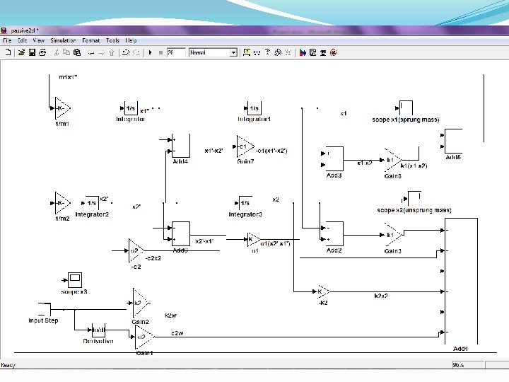
ANALYSYS OF PASSIVE SUSPENSION SYSTEM � MODELING AND ANALYSIS OF SINGLE DOF SYSTEM USING Simulink®: �Assumptions: • Only vertical displacement of the car is considered (no roll or pitch); • The springs and dampers are assumed to be mass-less; • The tire has no mass or dampening properties associated with it. Figure 5: An automobile passing through a pothole
� Given Parameters: Sprung mass =500 kg Stiffness of spring =1000 N/m Damping coefficient C=10 N-s/m Car’s vertical displacement (hole depth) = 0. 15 m � Governing Equation: …. . (3. 3) Input: Displacement of tire y= hstart= 22. 5 m, hend= 22. 55 m
Fig. 6. Simulink model of 1 degree of freedom passive suspension system
Results: : � Input step signal: Sprung mass displacement: The simulink model is simulated for given parameters and sprung mass displacement (x)(mm)) vs. time(sec)
� Sprung mass acceleration: � Figure 3. 7: Sprung mass acceleration (m/s 2) vs. time(s)
�Influence of damping(c)- When the dampening coefficient is increased, the oscillations that occurs in the system are decreased. � 1. Parameters: k=1000 N/m, c=300 N-s/m Figure 3. 7(a): Sprung mass acceleration (m/s 2) at c=300 N-s/m vs. time(s)
� MODELING AND ANALYSIS OF 2 DOF SYSTEM USING Simulink® � Figure 7: 2 DOF Quarter car model of passive suspension system (Image: Florin et al. 2006) Sprung mass-m 1 466. 5 (kg) Unsprung mass-m 2 49. 8 (kg) Stiffness of tyre-k 1 5700 (N/m) Stiffness of suspension-k 2 135000 (N/m) Coefficient of damper-c 1 650 (N/m/s) Coefficient of damping of tire –c 2 1400 (N/m/s)
Results: Road profile: Road input signal is given by step input function which represents a bump on the road with amplitude of 0. 10 m. Figure 8: step input signal (y) vs. time(s) � Sprung mass displacement: The simulink model is simulated for 20 seconds under step input road signal and the deflection of sprung mass or car body (x 1) is plotted Figure 9: Sprung mass displacement (x 1) (m) vs. time(s)
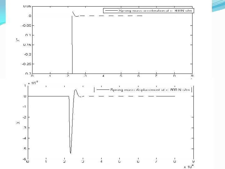
�Sprung mass acceleration: � The simulink model is simulated for 20 seconds under step input road signal and the velocity of sprung mass or car body is plotted as shown in fig. Figure 10: Sprung mass acceleration (m/s 2) vs. time(s) � Initially acceleration of the car body is at zero but as soon as it hits the bump accelerates up to 4. 75 m/s 2. After 5 seconds the acceleration reduces to zero because of damping effect
Unsprung mass displacement and acceleration: Figure 11: Unsprung mass displacement (x 2) vs. time(s) Figure 12: Unsprung mass acceleration (x 2’’)(m/s 2) vs. time(s)
Suspension deformation: �Initially deformation of the suspension is at zero but as soon as it hits the bump deflects up to. 05 m. After 6 seconds the deflection reduces to zero because of damper and spring. Figure 13: Suspension deformation (x 1 -x 2)(m) vs. time(s)
Conclusions: �In this chapter, we modelled the 2 degree of freedom quarter car model passive system and simulated in matlab simulink. A step type signal (road bump) was used for a broad application of the suspension system. �To analyse the road holding and comfort, car body acceleration and suspension deformation graphs were plotted. The parameters of a passive suspension system are generally fixed, being chosen to achieve a certain level of compromise between ride comfort and handling. So, in next chapter semi-active suspension system is proposed analysed for ride comfort and handling.
SEMI-ACTIIVE SUSPENSION SYSTEM � The spring for the suspension is assumed to be linear and the tire is also modelled as linear spring component. � The model has a sprung mass which is ¼ of vehicle’s mass, unsprung mass is the wheel mass, k 2 is the suspension spring stiffness, k 1 is tire stiffness and Co is variable damping coefficient. Equations of motion: ……. . 4. 1 ……. (4. 2) Figure 4. 1: Two DOF quarter car model of Semi-active suspension system
Figure 4. 2: Simulink model of semi-active suspension
Skyhook Control: � Skyhook control strategy is used so that damping force can be varied and sprung mass acceleration can be reduced to achieve comfort. � Semi-active dampers allow for the damping coefficient, and therefore the damping force, to be varied between high and low levels of damping. � First define the velocity of the suspended mass relative to the base, V 12, to be positive when the base and mass are separating (i. e. , when V 1 is greater than V 2) for both systems � Now assume that for both systems, the suspended mass is moving upwards with a positive velocity V 1. If we consider the force that is applied by the skyhook damper to the suspended mass, we notice that it is in the negative x 1 direction, Fsky = - Csky* V 1
� Next, we need to determine if the semi-active damper is able to provide the same force. � If the base and suspended mass in are separating, then the semi-active damper is in tension. Thus, the force applied to the suspended mass is in the negative X 1 direction Fc × Cc= - V 12 � Since we are able to generate a force in the proper direction, the only requirement to match the skyhook suspension is Cc= � We can apply the same simple analysis to the other two combinations of V 1 and V 12, resulting in the well-known semi-active skyhook control policy ………………. . Eqn. (4. 3)
� According to the Skyhook working principle, the semi-active on-off control law for a 2 Degree of freedom system is ………………Eqn. (4. 3) � 4. 4. 3. 2. Modeling of skyhook controller using Simulink: Figure 4. 4: Simulink model of Skyhook Controller
Incorporating skyhook controller model in semiactive suspension model:
5. SIMULATION RESULTS AND ANALYSIS OF SEMI-ACTIVE SUSPENSION SYSTEM � 5. 1. Simulation of the Semi-active Suspension with skyhook control: �Assuming road profile as step input with amplitude 0. 10 m which represents the road bump, the semi-active suspension model with skyhook control is simulated for 5 sec and various graphs are plotted. �TABLE 4. 4: System parameters used Sprung mass-m 2 240 kg Unsprung mass-m 1 36 kg Stiffness of tyre-k 1 160000 N/m Stiffness of suspension-k 2 16000 N/m
� 5. 1. 1. Road profile input: For this study step input road profile signal is used with amplitude of 0. 10 m is given and different results will be obtained. Figure 5. 2: Road profile input (m) vs. time (s)
5. 1. 2. Sprung mass displacement: . Initially car body displacement or sprung mass displacement is zero but after 1 sec when it meets the bump, the displacement increases. The oscillations reduce in 1. 5 seconds due to damping effect. Figure 5. 3: Sprung mass displacement (m) vs. time(s)
� 5. 1. 3. Sprung mass velocity: Initially velocity of the car body is at zero but when it experiences a bump, reaches to amplitude of 1. 15 m/s. The vibration reduces due to damping and sprung mass velocity becomes zero after 3 seconds. Figure 5. 4: Sprung mass velocity (m/s) vs. time(s)
� 5. 1. 4. Sprung mass acceleration: �it can be seen that sprung mass acceleration is high at starting but reduces to zero after 2. 5 seconds. � Figure 5. 5: Sprung mass acceleration (m/s 2) vs. time(s)
� 5. 1. 5. Unsprung mass displacement (m) vs. time(sec) � 5. 1. 6 Unsprung mass velocity (m/s) vs. time(sec)
� 5. 1. 8. Skyhook control force (N) vs. time(sec) 5. 1. 9. Skyhookdamping (N-s/m) vs. time(sec)
� 5. 1. 10. Suspension deformation: Suspension deformation is high at starting but reduces very quickly. From fig. 5. 1 simulink model is simulated for 5 sec and suspension deformation (z 2 -z 1) is plotted �Suspension oscillations reduce to zero after 2 seconds so this system has good damping characteristics and road holding. Figure 5. 11: Suspension deformation (m) vs. time(s)
Comparison between semi-active suspension system and passive suspension system: �Both semi-active and passive systems are simulated for same step input road profile of amplitude 0. 10 m and for same sprung mass, unsprung mass and tire stiffness. Then sprung mass acceleration and suspension deformation graphs are plotted to understand the damping characteristics of both the systems. �Passive system has constant damping of 1400 N-s/m 2 throughout the simulation and semi-active suspension has variable stiffness from 1000 N-s/m 2 to 4000 N-s/m 2. Minimum and maximum damping of semi-active are set in skyhook control model and it calculates the required damping force and damping coefficient at different time step so that body oscillations and suspension deformations are minimum.
Passive and semi-active suspension simulink model
� 5. 2. 1. Sprung mass acceleration: � It takes 6 seconds for passive system to reduce oscillations to zero. Semi-active suspension system with skyhook control has less car body acceleration magnitude and it takes only 2 seconds to reduce body acceleration. � Figure 5. 13: Sprung mass acceleration in Semi-active suspension mode and passive suspension mode
� 5. 2. 2. Suspension deformation: �. Initially deformation of the suspension is at zero but as soon as tire hits the bump passive suspension deflects up to. 12 m and semi-active suspension deflects up to 0. 05 m. Suspension oscillation reduces to zero after 6 seconds in case of passive system. There are more oscillations in passive mode till it reaches to zero. � Figure 5. 14: Suspension deformation in Semi-active suspension mode and passive suspension mode
� 5. 3: Road profile input (Pot hole): �Now another step-input function is given as input of amplitude (-0. 10) m which represents the pothole in the road. Figure 5. 15: Road profile input (pot hole)
� 5. 3. 1. Sprung mass acceleration: . It takes 4 seconds for passive system to reduce oscillations to zero. Semi-active suspension system with skyhook control has less car body acceleration magnitude and it takes only 2. 5 seconds to reduce body acceleration. Figure 5. 16: Sprung mass acceleration in Semi-active suspension mode and passive suspension mode
� 5. 3. 2. Suspension deformation: Initially deformation of the suspension is at zero but as soon as tire reaches to road bump passive suspension deflects up to -. 15 m and semi-active suspension deflects up to 0. 13 m. Suspension oscillation reduces to zero after 4 seconds in case of passive system. There are more oscillations in passive mode till it reaches to zero. Figure 5. 17: Sprung mass deformation in Semi-active suspension mode and passive suspension mode (Pothole road input)
5. 4. Summary of the results: � In order to evaluate the semi-active suspension, simulation tests were performed with sinusoidal road profile. Evaluation of the new suspension was done by comparing the passive and semi-active suspension modes. � Therefore, each test was performed once in the passive mode and then, in the semi-active mode. The achieved data from these tests in the two suspension modes were analyzed. � These results were plotted in Matlab Simulink. The sprung mass acceleration and suspension deformation were analyzed to evaluate the vibration characteristic of the suspension system. � Car body (sprung mass) accelerations of the car body were measured, and the influence of the new suspension system on the ride comfort capability of quarter car model was evaluated by comparing the results of the passive and semi-active suspension modes. � Semi-active suspension system is better in both ride comfort and suspension performance.
6. Conclusion and Future Scope: � 6. 1. Conclusion: The research presented in this report is directed to the simulation and modeling of a semi-active suspension. Although based on the well-known physical models for investigating the vertical dynamics of suspension systems, � It is expanded with an extensive set of simulations based on Simulink modeling and benchmark road profiles employed in real industrial tests. � The skyhook control strategy is evaluated by means of multiple criteria, i. e. , the comfort and handling. � In addition, it can be seen that skyhook control improves, in a significant way, comfort characteristics in comparison with the passive system
The main conclusions that may be derived are : 1. 2. A control approach based on skyhook algorithm for semi-active suspension systems has been implemented in the Simulink environment. In order to show the effectiveness of the proposed procedure, performance comparison with passive system has been presented. 3. Extensive simulation tests have been performed on the quarter-car linear models, which provide an accurate enough description of the dynamic behavior of a vehicle equipped with constant damping or varying damping control. 4. On the basis of the results, it can be concluded that the inclusion of the skyhook algorithm in a semi-active control system improves the comfort index of semi-active suspensions systems.
6. 2. Future scope: The possible extensions for this work are listed below: 1. Development of a full car model of semi-active suspension system with skyhook control is an important aspect of future work. 2. Development of different control strategies such as modified skyhook, PID control and fuzzy logic control for suspension system. 3. In this thesis, a step input response analysis of the suspension system has been conducted. As the real-life excitations to a vehicle are varied random inputs, more research on the nonlinear system response to a general random input is an important area for further study of suspension system design.
References: [1] Babak Ebrahimi, (2009), Ph. D. thesis on ‘Development of Hybrid Electromagnetic Dampers for Vehicle Suspension Systems’ University of Waterloo, Canada [2] Karnopp D. , (2007)Active damping in road vehicle suspension systems, Vehicle System Dynamics, 12, (1983) 291 -316. [3] Gillespie T. , (2006) Development of semi-active damper for heavy off-road military vehicles, M. Sc. Thesis, University of Waterloo [4] Johnsson et al, (2003). Methods for road texture estimation using vehicle Measurements, Luleå University of Technology [5] Karnopp et al, (1974) Vibration control using semi-active force generators, Transaction of ASME, Journal of Engineering for Industry, 96, 619 -626 [6] Guglielmino et al, (2008). Semi-active Suspension Control, springer, ISBN 978 -1 -84800 -231 -9 [7] Nima Eslaminasab, (2008) Ph. D. thesis on ‘Development of a Semi-active Intelligent Suspension System for Heavy Vehicles’ University of Waterloo, Canada [8] Yi, K. S. , Song, B. S. (1999), Observer design for semi-active suspension control. Vehicle System Dynamics, vol. 32, p. 129148, DOI: 10. 1076/vesd. 32. 2. 129. 2093. [9] Carter et al, (1998). Master’s thesis, Application of Magnetorheological Dampers For vehicle Seat Suspensions, etd-7398152720 [10] Turnip, A. et al, (2008) Control of a semi-active MR-damper suspension system: A new polynomial model. Proceedings, The International Federation of Automatic Control. Seoul, p. 4683 -4688 [11] Jazar, R. (2009). Vehicle Dynamic: Theory and Application, Springer, New York. [12] Abramov, S. et al, (2009), Semi-active suspension system simulation using Simulink, International Journal of Engineering System Modelling and Simulation, vol. 1, no. 2/3, p. 101 -114. [13] Rill, G. , (2009)Vehicle Dynamics, University of Applied Science, Regensburg, . [14] Popp, et al. (2010). Ground Vehicle Dynamics. Springer, Berlin, DOI: 10. 1007/978 -3 -540 - 68553 -1. [15] Kuznestov et al. , (2011). Optimization of improved suspension system with inerter device of the quarter-car model in vibration analyses. Archive of Applied Mechanics, vol. 81, no. 10, p. 1427 -1437. [16] Karnopp, D. , (1995) "Active and Semiactive Vibration Isolation, " Journal of Vibrations and Acoustics, Vol. 117, No. 3 B, pp. 177 -185.
K N A H T ! ! ! U O Y