Simple vapor Compression Refrigeration cycle Prof Dr M


Pressure of refrigerant in evaporator reduced below atmospheric by action of a vapor pump.")
Float valve assembly maintains constant liquid level in evaporator. The pressure")
Serpentine coil evaporator with thermostatic expansion valve refrigerant control. The float type of control")


- Slides: 17
Simple vapor Compression Refrigeration cycle Prof. Dr. M. M. Nasr Professor of refrigeration and air conditioning Minia university
Intoduction Refrigeration by evaporation Vaporizing the Refrigerant. An insulated space can be adequately refrigerated by merely allowing liquid R-12 to vaporize in a container vented to the outside as shown in Fig. ( ). The Refrigerant-12 liquid vaporizes as it takes in heat from the 2°C space. The heat taken in by the refrigerant leaves the space in the vapor escaping through the vent. Since the R 12 is under atmospheric pressure, its saturation temperature is – 29. 8° C.
Controlling the Vaporizing Temperature. The temperature at which the liquid vaporizes in the evaporator can be controlled by controlling the pressure of the vapor over the liquid, which in turn is governed by regulating the rate at which the vapor escapes from the evaporator. a)The boiling temperature of the liquid refrigerant in the evaporator is controlled by controlling the pressure of the vapor over the liquid with the throttling valve in the vent. It is possible to control the pressure of the vapor over the liquid and cause the R-12 to vaporize at any desired temperature between – 29. 8° C and the space temperature.
b)Pressure of refrigerant in evaporator reduced below atmospheric by action of a vapor pump. When vaporizing temperatures below– 29. 8° C are required, it is necessary to reduce the pressure in the evaporator to some pressure below atmospheric. This can be accomplished through the use of a vapor pump as shown in (b).
Adding flow control a)Float valve assembly maintains constant liquid level in evaporator. The pressure of the refrigerant is reduced as the refrigerant passes through the needle valve.
b)Serpentine coil evaporator with thermostatic expansion valve refrigerant control. The float type of control has some disadvantages, mainly bulkiness, which tend to limit its use to some few special applications. The most widely used type of refrigerant flow control is thermostatic expansion valve.
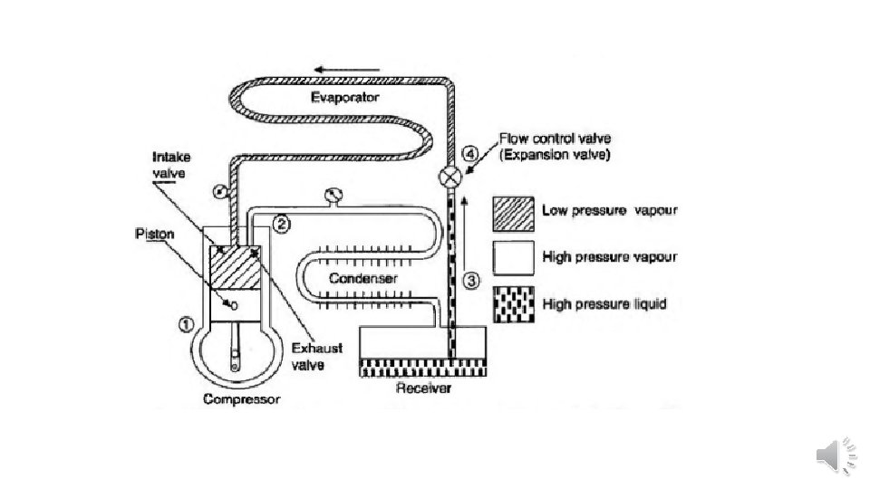
Salvaging the Refrigerant. It is not practical to permit the refrigerant vapor to escape to the outside and be lost by diffusion into the air. The vapor must be collected continuously and condensed back into the liquid state so that the same refrigerant is used over and over again, thereby eliminating the need for ever replenishing the supply of refrigerant in the system. Collecting and condensing the refrigerant vapor. Refrigerant absorbs heat in evaporator and gives off heat in the condenser.
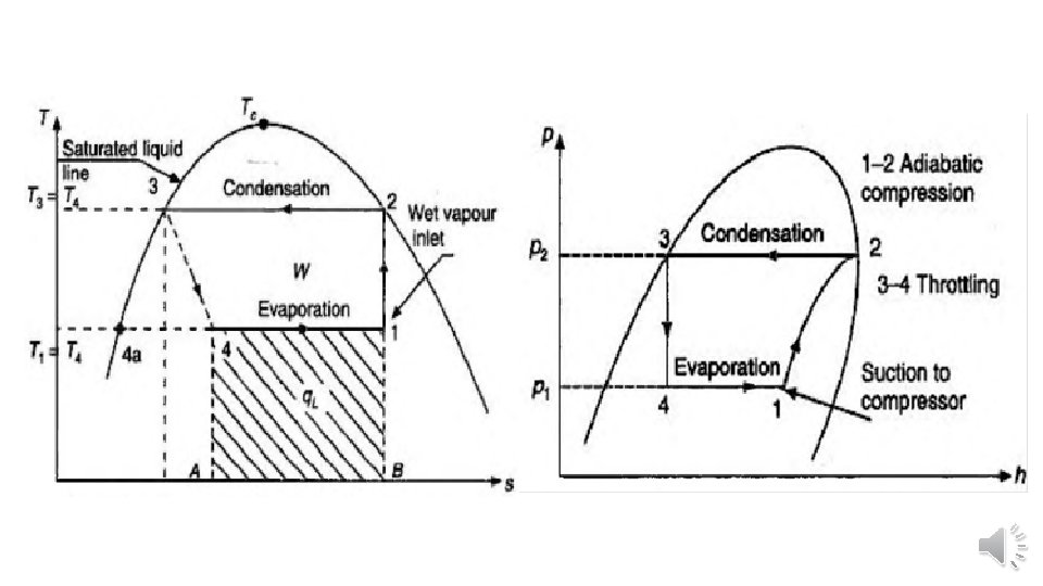
Simple Vapor Compression Refrigeration Systems • Assumptions made in theoretical vapor compression cycle • * All the processes involved in the cycle are assumed to be reversible. • * There is no internal and external friction between the refrigerant and the metallic surface of the heat exchangers (evaporator and condenser). Hence any pressure drop is neglected. • * There is no heat gain or loss except in evaporator and condenser. • Compression process (1 -2 ) • The compressor takes the dry saturated refrigerant vapor during its suction stroke at pressure p 1, Then the vapor is compressed to pressure p 2 isentropically during its compression stroke. • Condensation process (2 -3 ) • The function of the condenser is to remove heat from vapor refrigerant so that it changes to liquid phase. • Expansion process (3 -4 ) • The high pressure liquid from state point 3 is expanded through an expansion valve, also called throttle valve, during which the enthalpy remains constant • Evaporation process (4 -1 ) • Evaporation of liquid refrigerant takes place in a heat exchanger called evaporator. The function of an evaporator is to transfer heat from its space to the refrigerant
Vapor compression cycle on T-s diagram, and p-h diagram
Piston Displacement.
• Wet compression vs dry compression • In case the compression process involves the compression of dry saturated vapor or with slightly superheated vapor, it is called dry compression. In this case the complete compression process remains in superheated state. • In case the compression process involves the compression of wet refrigerant, the compression is called wet compression. • The refrigerant vapor would be compressed efficiently if there is a perfect sealing between the piston and the cylinder bore. This would be satisfied to a certain extent with better surface finish obtained in the manufacturing process. In a reciprocating compressor, the lubricating oil serves two purposes: • (i) It reduces the friction between the rubbing surfaces, and • (ii) it acts as a sealing agent between the piston and the cylinder.
Thanks Prof. Dr. M. M. Nasr Mechanical Power and Energy Dept.