
SIMG217 Fundamentals of Astronomical Imaging Instructor Joel Kastner














- Slides: 82
SIMG-217 Fundamentals of Astronomical Imaging Instructor: Joel Kastner Office: 17 -3190 Phone: 475 -7179 Email: kastner@cis. rit. edu
Course Description Familiarizes students with the goals and techniques of astronomical imaging. The broad nature of astronomical sources will be outlined in terms of requirements on astronomical imaging systems. These requirements are then investigated in the context of the astronomical imaging chain. Imaging chains in the optical, infrared, X-ray, and/or radio wavelength regimes will be studied in detail as time permits. (prerequisite: 1051 -215 or permission of instructor)
Laboratories • 3 mandatory experiments, selected from: – – • Star Colors from Digital Images Spectroscopic Imaging of Gases Multiwavelength Imaging of the Sun Multiwavelength Imaging of the Orion Nebula Final Project; one of: – – – collect/process images taken at RIT observatory (weather, time permitting) detailed followup of one of the above lab experiences Student-proposed project/investigation in astronomical imaging
Topics • • Review of Imaging Systems Issues in Astronomical Imaging Systems History of Astronomical Imaging Systems Contemporary Astronomical Imaging Systems • What does the future hold for astronomical imaging?
Goal of Imaging Systems • Create an “image” of a scene that may be measured to calculate some parameter of the scene – Diagnostic X ray – Digital Photograph – “CAT” Scan (computed tomography) – “MRI” (magnetic resonance imaging)
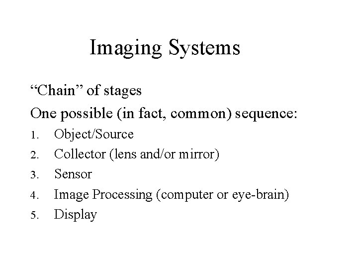
Imaging Systems “Chain” of stages One possible (in fact, common) sequence: 1. 2. 3. 4. 5. Object/Source Collector (lens and/or mirror) Sensor Image Processing (computer or eye-brain) Display
Issues in Astronomical Imaging • Distances between objects and Earth • Intrinsic “brightness” of object – generally very faint large image collectors – large range of brightness (dynamic range) • Type of energy emitted/absorbed/reflected by the object – wavelength regions • Other considerations: – motion of object – brightness variations of object
Astronomical Imaging: Overview • When you think of a clear, dark night sky, what do you visualize? – The human visual system is fine-tuned to focus, detect, and process (i. e. , create an “image” of) the particular wavelengths where the Sun emits most of its energy • evolutionary outcome – we see best in the dominant available band of wavelengths – As a result, when we look at the night sky, what we see is dominated by starlight (like the sun) • We think of stars and planets when we think of astronomy
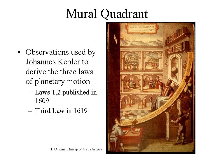
History of Astronomical Imaging Systems • Oldest Instruments, circa 1000 CE – 1600 CE – Used to measure angles and positions – Included No Optics • Astrolabe • Octant, Sextant • Tycho Brahe’s Mural Quadrant (1576) – Star Catalog accurate to 1' (1 arcminute, limit of human resolution) • Astronomical Observatories as part of European Cathedrals
Mural Quadrant • Observations used by Johannes Kepler to derive three laws of planetary motion – Laws 1, 2 published in 1609 – Third Law in 1619 H. C. King, History of the Telescope
History of Astronomical Imaging Systems • Optical Instruments, (1610+) – Refracting Telescope • Galileo • Lippershey • Hevelius – Reflecting Telescope • Newton (ca 1671) – Spectroscope • Newton
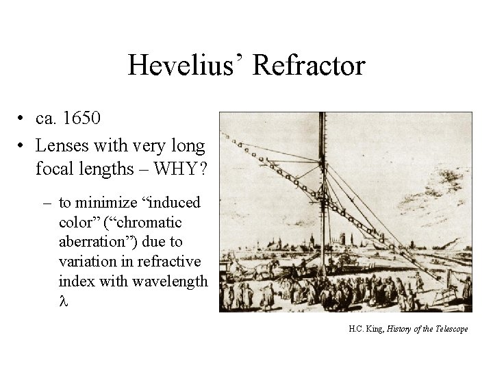
Hevelius’ Refractor • ca. 1650 • Lenses with very long focal lengths – WHY? – to minimize “induced color” (“chromatic aberration”) due to variation in refractive index with wavelength H. C. King, History of the Telescope
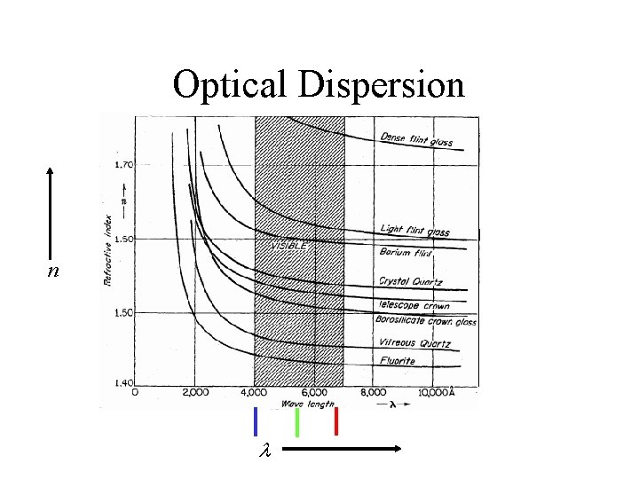
Optical Dispersion n
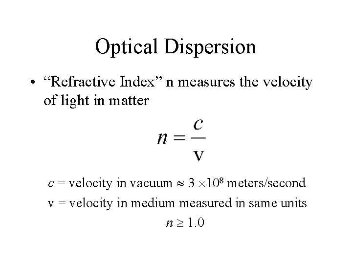
Optical Dispersion • “Refractive Index” n measures the velocity of light in matter c = velocity in vacuum 3 108 meters/second v = velocity in medium measured in same units n 1. 0
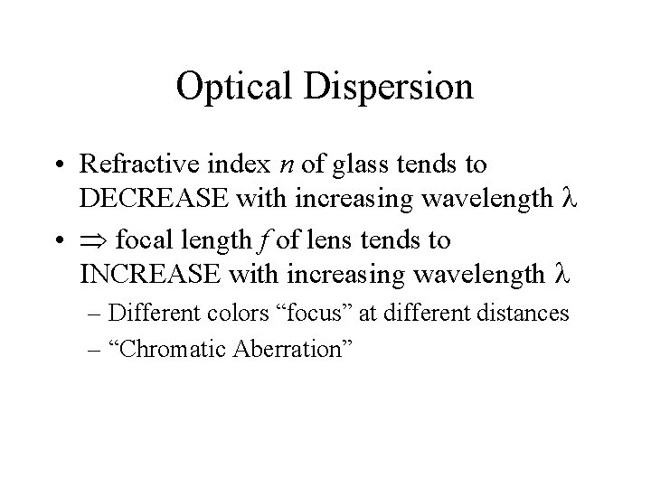
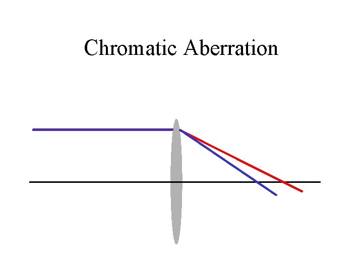
Optical Dispersion • Refractive index n of glass tends to DECREASE with increasing wavelength • focal length f of lens tends to INCREASE with increasing wavelength – Different colors “focus” at different distances – “Chromatic Aberration”
Chromatic Aberration
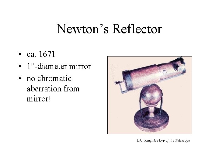
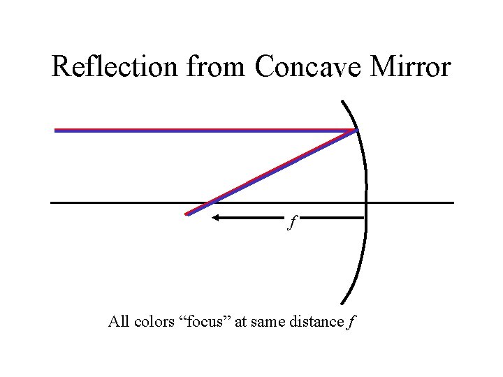
Newton’s Reflector • ca. 1671 • 1"-diameter mirror • no chromatic aberration from mirror! H. C. King, History of the Telescope
Reflection from Concave Mirror f All colors “focus” at same distance f
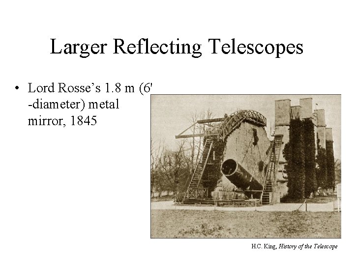
Larger Reflecting Telescopes • Lord Rosse’s 1. 8 m (6' -diameter) metal mirror, 1845 H. C. King, History of the Telescope
History of Astronomical Imaging Systems • Image Recording Systems – Chemical-based Photography • wet plates, 1850 + • dry plates, 1880+ • Kodak plates, 1900+ – Physics-based Photography, 1970 + • Electronic Sensors, CCDs
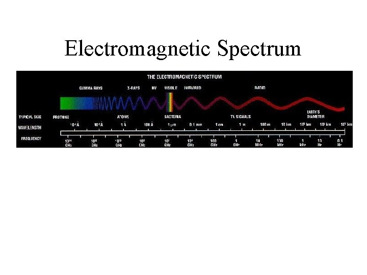
Electromagnetic Spectrum
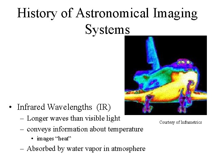
History of Astronomical Imaging Systems • Infrared Wavelengths (IR) – Longer waves than visible light – conveys information about temperature • images “heat” – Absorbed by water vapor in atmosphere Courtesy of Inframetrics
History of Astronomical Imaging Systems • Infrared Astronomy – Wavelengths are longer than for visible light • IR wavelengths range from ~1 micron to ~200 microns – Over major portions of this range, IR is absorbed by water vapor in atmosphere
Infrared Astronomy • Because infrared light is generated by any “warm” objects, detector must be cooled to a lower temperature – Uncooled detector is analogous to camera with an internal light source • camera itself generates a signal • Cooling is a BIG issue in Infrared Astronomy
History of Astronomical Imaging Systems • History of Astronomical Infrared Imaging – 1856: using thermocouples and telescopes (“one-pixel sensors”) – 1900+: IR measurements of planets – 1960 s: IR survey of sky (Mt. Wilson, single pix detector) – 1983: IRAS (Infrared Astronomical Satellite) – 1989: COBE (Cosmic Background Explorer)
History of Astronomical Imaging Systems: Infrared Astronomy • Airborne Observatories – – Galileo I (Convair 990), 1965 – 4/12/1973 (crashed) Frank Low, 12"–diameter telescope on NASA Learjet, 1968 Kuiper Airborne Observatory (KAO) (36"–diameter telescope) Stratospheric Observatory for IR Astronomy (under development: 2. 4 -meter diameter telescope on 747) • Spaceborne Observatories – – – “Orbiting Astronomical Observatory” (OAO), 1960 s “Infrared Astronomical Satellite” (IRAS), 1980 s Hubble Space Telescope (HST), 1990 (some IR astronomy) Infrared Satellite Observatory (ISO), 1995 -1998 Spitzer Space Telescope (Aug. 2003 -present)
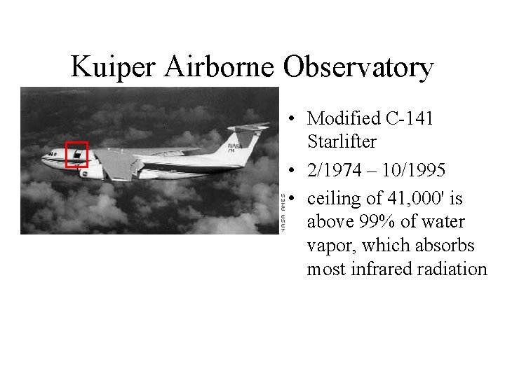
Kuiper Airborne Observatory • Modified C-141 Starlifter • 2/1974 – 10/1995 • ceiling of 41, 000' is above 99% of water vapor, which absorbs most infrared radiation
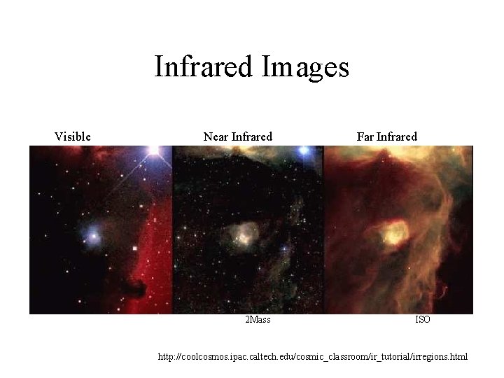
Infrared Images Visible Near Infrared 2 Mass Far Infrared ISO http: //coolcosmos. ipac. caltech. edu/cosmic_classroom/ir_tutorial/irregions. html
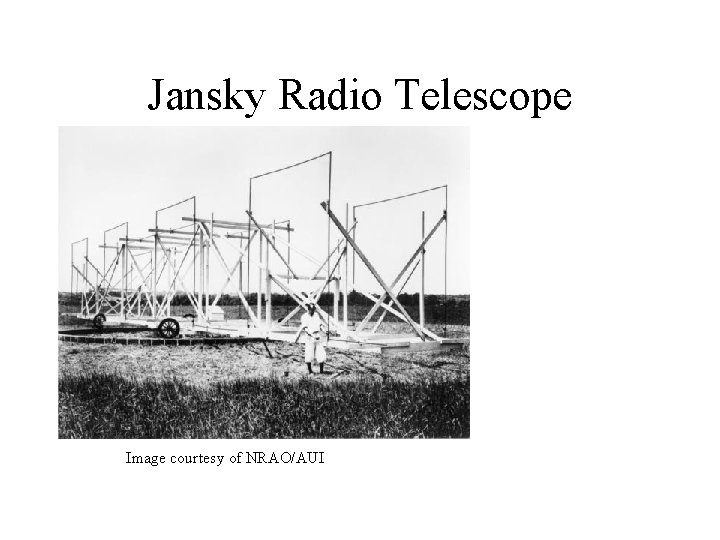
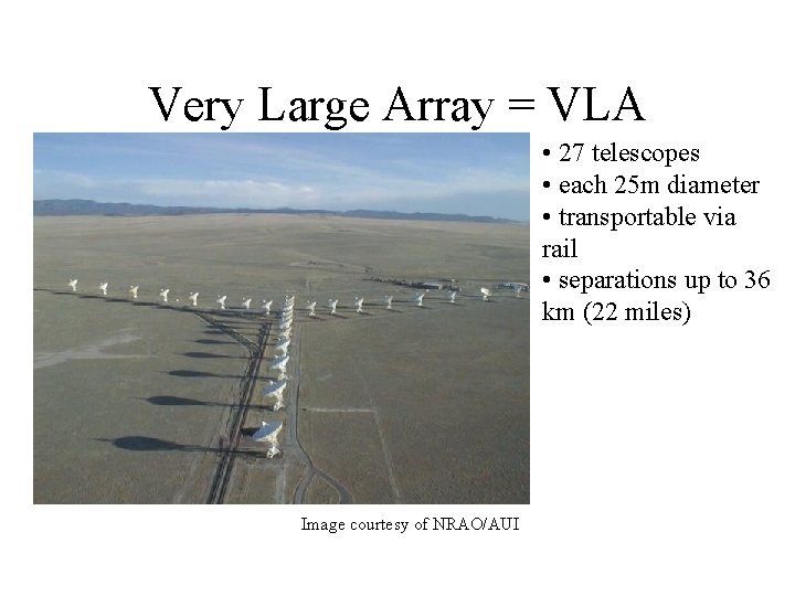
History of Astronomical Imaging Systems: Radio Astronomy • Radio Waves – Wavelengths are much longer than visible light • millimeters (and longer) vs. hundreds of nanometers • Selective History – 1932: Karl Jansky (Bell Telephone Labs) investigated use of “short waves” for transatlantic telephone communication – 1950 s: Plans for 600 -foot “Dish” in Sugar Grove, WV (for receiving Russian telemetry reflected from Moon) – 1963: Penzias and Wilson (Bell Telephone Labs), “Cosmic Microwave Background” – 1980: “Very Large Array” = VLA, New Mexico
Jansky Radio Telescope Image courtesy of NRAO/AUI
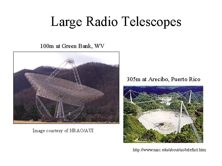
Large Radio Telescopes 100 m at Green Bank, WV 305 m at Arecibo, Puerto Rico Image courtesy of NRAO/AUI http: //www. naic. edu/about/ao/telefact. htm
Very Large Array = VLA • 27 telescopes • each 25 m diameter • transportable via rail • separations up to 36 km (22 miles) Image courtesy of NRAO/AUI
Issues in Astronomical Imaging • Distances between objects and Earth • Intrinsic “brightness” of object • Type of energy emitted/absorbed/reflected by the object – wavelength regions • Motion of object
What “Information” is Available from Astronomical Objects? • Emission of Matter – Particles (protons, electrons, ions) • “solar wind” • solar “magnetic storm” aurorae (“northern lights”) • Emission of Energy – Light (in photon and/or wave model) • visible light • “invisible” light (ultraviolet, infrared, radio waves, X rays, . . . ) • “Interaction” of matter and light – Absorption/Reflection • Matter can obscure light
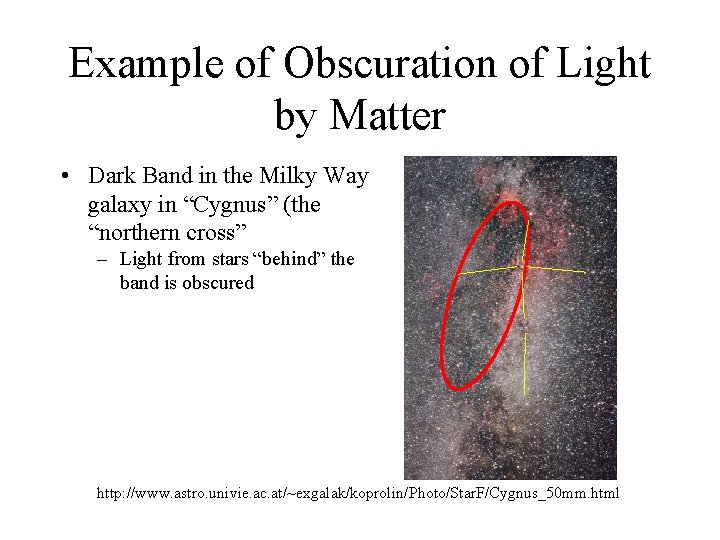
Example of Obscuration of Light by Matter • Dark Band in the Milky Way galaxy in “Cygnus” (the “northern cross” – Light from stars “behind” the band is obscured http: //www. astro. univie. ac. at/~exgalak/koprolin/Photo/Star. F/Cygnus_50 mm. html
The “Task” of Imaging • Collect the “information” from the object – emitted light or particles – absorbed light • “Organize” it = “arrange” it • View it • Make judgments based upon observations
Problems of Astronomical Imaging • Objects are “Faint” – little energy reaches Earth – must expose for a “long” period of time to collect enough information (energy) • Effects of Earth’s Atmosphere – “twinkling”, disrupts images – absorption of atmospheric molecules • good and bad! – reason for space-based observatories
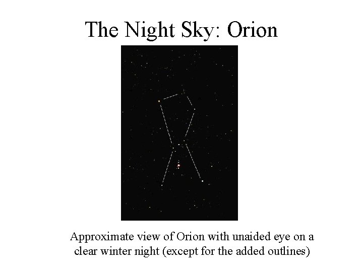
The Night Sky: Orion Approximate view of Orion with unaided eye on a clear winter night (except for the added outlines)
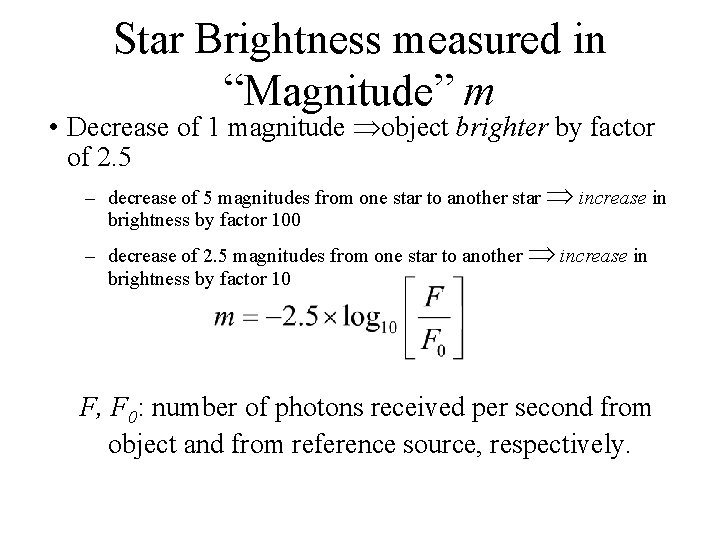
Star Brightness measured in “Magnitude” m • Uses a “reversed” logarithmic scale • Smaller Magnitudes Brighter Object (“golf score”) – – – Sun: m -27 Full Moon: m -12 Venus (at maximum brilliancy): m -4. 7 Sirius (brightest distant star): m -1. 4 Faintest stars visible to unaided eye: m +5 to +6
Star Brightness measured in “Magnitude” m • Decrease of 1 magnitude object brighter by factor of 2. 5 – decrease of 5 magnitudes from one star to another star increase in brightness by factor 100 – decrease of 2. 5 magnitudes from one star to another increase in brightness by factor 10 F, F 0: number of photons received per second from object and from reference source, respectively.
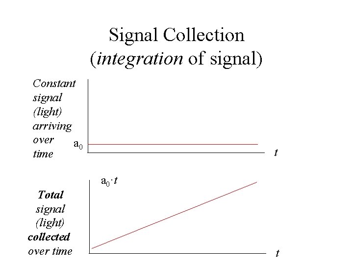
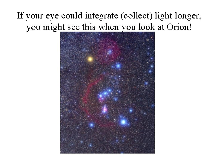
Magnitudes and Human Vision – Sensitivity of human vision is limited (in large part) by the length of time your brain can wait to receive and interpret the signals from the eye • How long is that? • How do you know? Time between movie frames = 1/24 second Time between video frames = 1/30 second • Eye collects light for about 1/20 second before reporting to brain – What if your retina could store collected signal over much longer times before reporting to the brain?
Signal Collection (integration of signal) Constant signal (light) arriving over a 0 time Total signal (light) collected over time t a 0·t t
If your eye could integrate (collect) light longer, you might see this when you look at Orion!
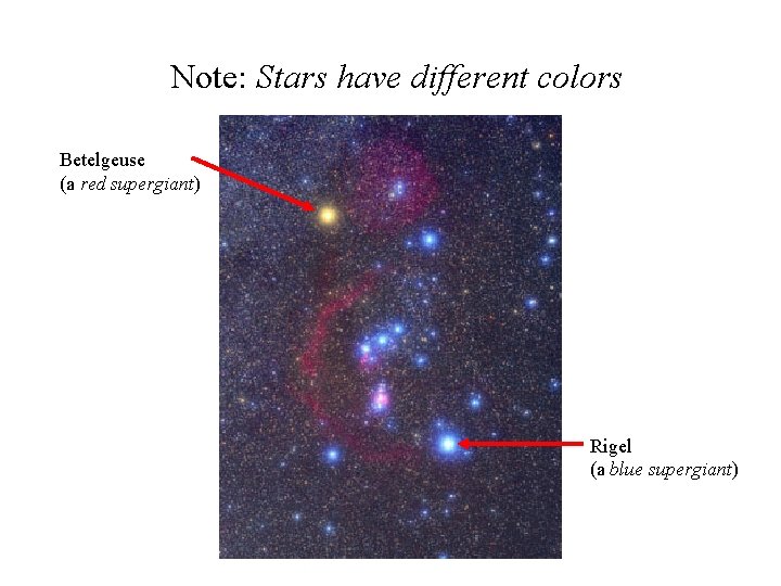
Note: Stars have different colors Betelgeuse (a red supergiant) Rigel (a blue supergiant)
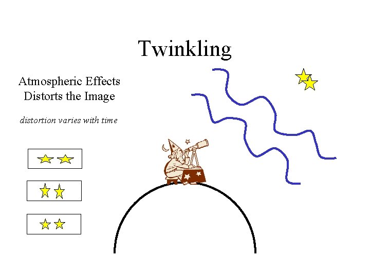
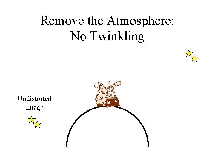
“Twinkling” • Obvious when viewing stars, e. g. , Sirius – “point source” • Not apparent when viewing planets – “finite-size source” • One Rationale for Space Observatories
Twinkling Atmospheric Effects Distorts the Image distortion varies with time
Remove the Atmosphere: No Twinkling Undistorted Image
Stellar “Speckle” • Motivation for “Adaptive Optics” (AO) – Detect and “undo” the distortions of the atmosphere on the images – “Rubber-mirror” telescopes – http: //op. ph. ic. ac. uk/ao/overview. html
Space Observatories • Located “above” the atmosphere – No “twinkling” – No absorption of wavelengths • BUT: How to get the data down? – LOTS of data • EACH 4000 RGB color image has 96 Megabytes of data (4000 2 3) – Data transfer rate is important
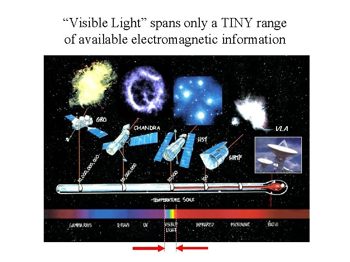
“Visible Light” spans only a TINY range of available electromagnetic information VLA
Differences Among Telescopes • Mechanism of Light Collection – Reflection • Diameters of Light “Collectors” • Length of Optical Train • Sensors
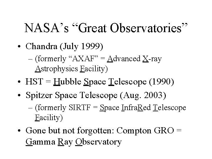
NASA’s “Great Observatories” • Chandra (July 1999) – (formerly “AXAF” = Advanced X-ray Astrophysics Facility) • HST = Hubble Space Telescope (1990) • Spitzer Space Telescope (Aug. 2003) – (formerly SIRTF = Space Infra. Red Telescope Facility) • Gone but not forgotten: Compton GRO = Gamma Ray Observatory
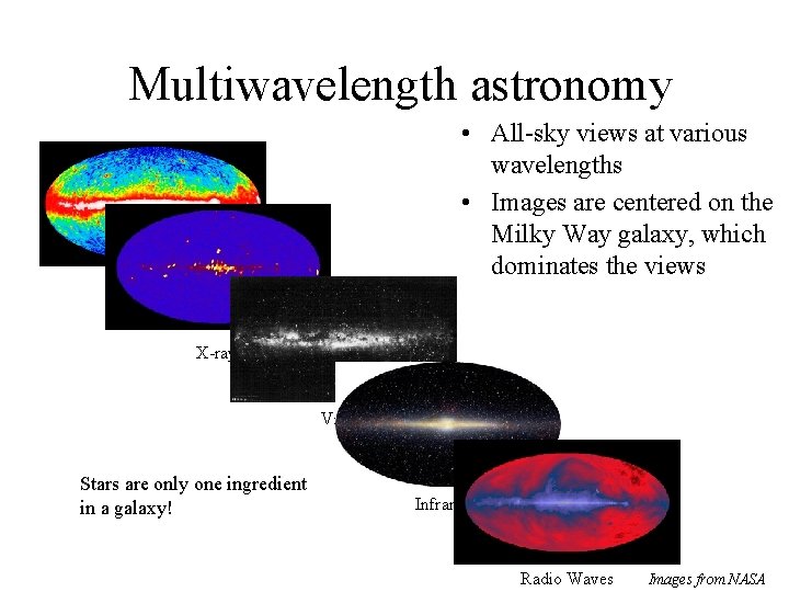
Multiwavelength astronomy • All-sky views at various wavelengths • Images are centered on the Milky Way galaxy, which dominates the views Gamma Ray X-ray Visible Stars are only one ingredient in a galaxy! Infrared Radio Waves Images from NASA
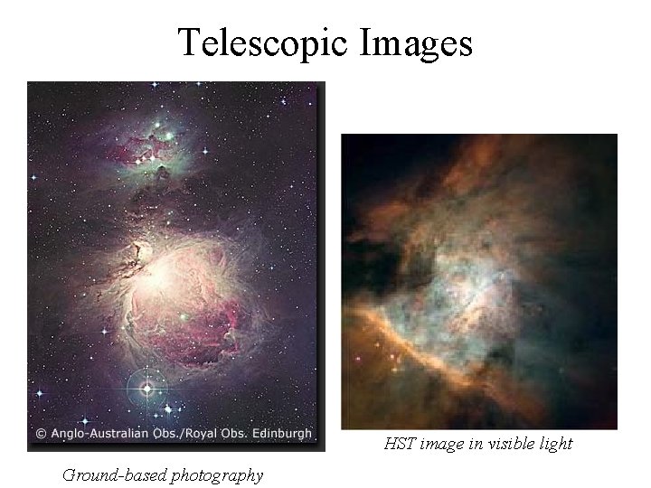
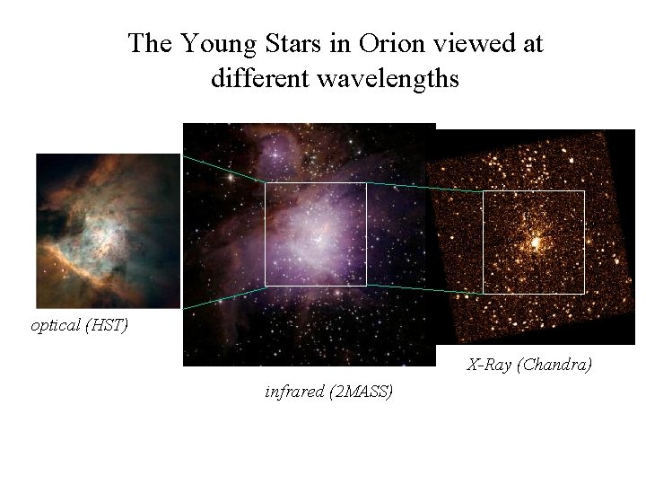
Orion Nebula (Messier # 42 = M 42) Cloud of dust and gas Stellar “Nursery”
Telescopic Images HST image in visible light Ground-based photography
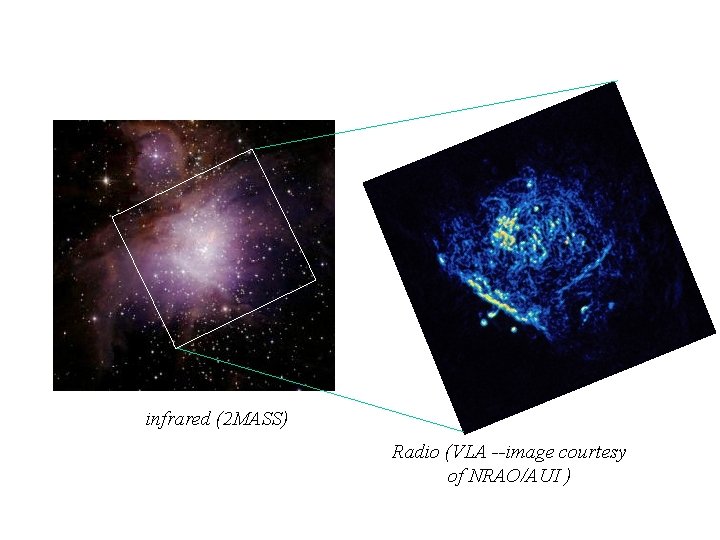
The Young Stars in Orion viewed at different wavelengths optical (HST) X-Ray (Chandra) infrared (2 MASS)
infrared (2 MASS) Radio (VLA --image courtesy of NRAO/AUI )
Other Issues in Astronomical Imaging • Resolution • Motion
Resolution • Depends on wavelength – Longer waves “poorer” resolution for same size telescope – Radio telescopes have HUGE collectors – Motivation for “indirect” imaging algorithms • “interferometry” • increases resolution in a limited number of directions
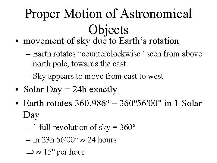
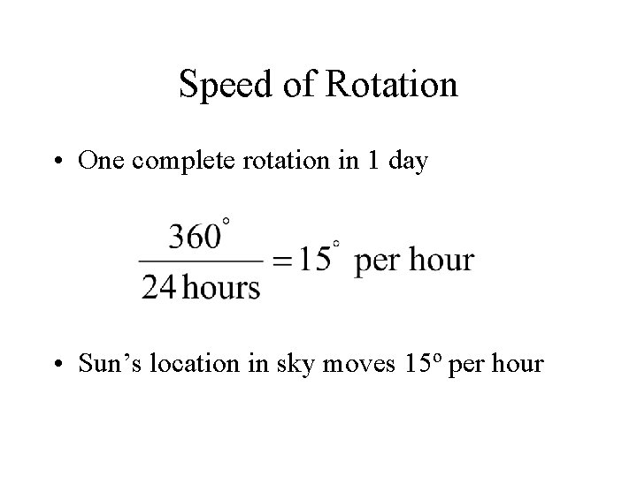
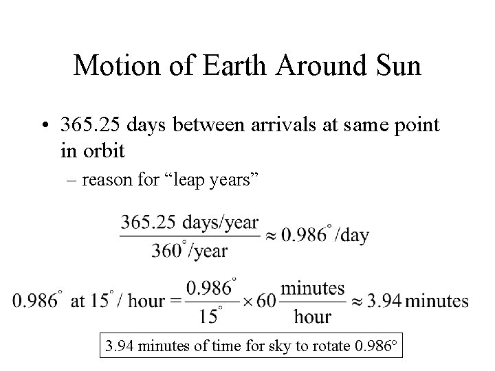
Proper Motion of Astronomical Objects • movement of sky due to Earth’s rotation – Earth rotates “counterclockwise” seen from above north pole, towards the east – Sky appears to move from east to west • Solar Day = 24 h exactly • Earth rotates 360. 986º = 360º 56'00" in 1 Solar Day – 1 full revolution of sky = 360º – in 23 h 56'00“ 24 hours 15º per hour
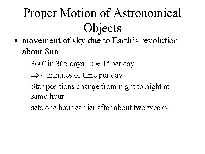
Proper Motion of Astronomical Objects • movement of sky due to Earth’s revolution about Sun – 360º in 365 days 1º per day – 4 minutes of time per day – Star positions change from night to night at same hour – sets one hour earlier after about two weeks
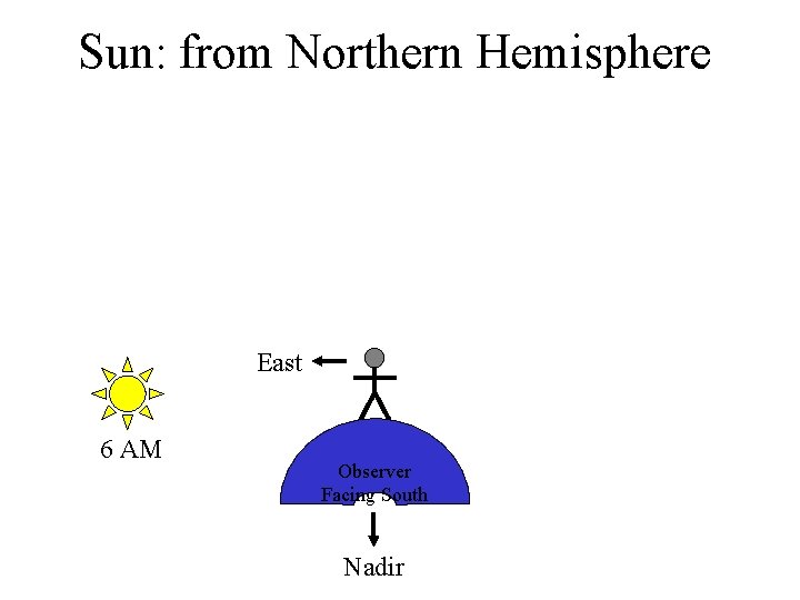
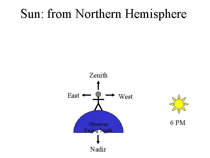
Sun: from Northern Hemisphere East 6 AM Observer Facing South Nadir
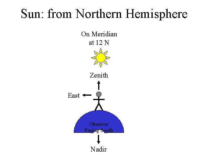
Sun: from Northern Hemisphere On Meridian at 12 N Zenith East Observer Facing South Nadir
Sun: from Northern Hemisphere Zenith East West Observer Facing South Nadir 6 PM
Sun: from Northern Hemisphere On Meridian at 12 N Zenith East 6 AM West Observer Facing South Nadir 6 PM Earth’s Rotation, W to E
Direction of Rotation of Earth • Sun Appears to: – “Rise” in East – “Set” in West • (Actually, the Horizon) – “Falls” in the East – “Rises” in the West • Earth rotates from West to East
Speed of Rotation • One complete rotation in 1 day • Sun’s location in sky moves 15º per hour
BUT! • Earth also revolves in its orbit about Sun
Earth’s Orbit January 15 January 1 n. b. , Earth is closest to Sun in January (orbit is elliptical, not circular)
Motion of Earth Around Sun • 365. 25 days between arrivals at same point in orbit – reason for “leap years” 3. 94 minutes of time for sky to rotate 0. 986º
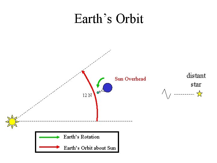
Earth’s Orbit distant star Earth’s location Observer’s midnight on day 1 12 M star is overhead AT midnight Earth’s Rotation Earth’s Orbit about Sun
Earth’s Orbit Sun Rises 6 AM Earth’s Rotation Earth’s Orbit about Sun distant star
Earth’s Orbit Sun Overhead 12 N Earth’s Rotation Earth’s Orbit about Sun distant star
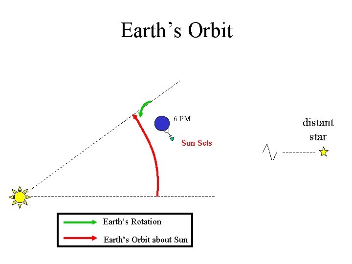
Earth’s Orbit 6 PM Sun Sets Earth’s Rotation Earth’s Orbit about Sun distant star
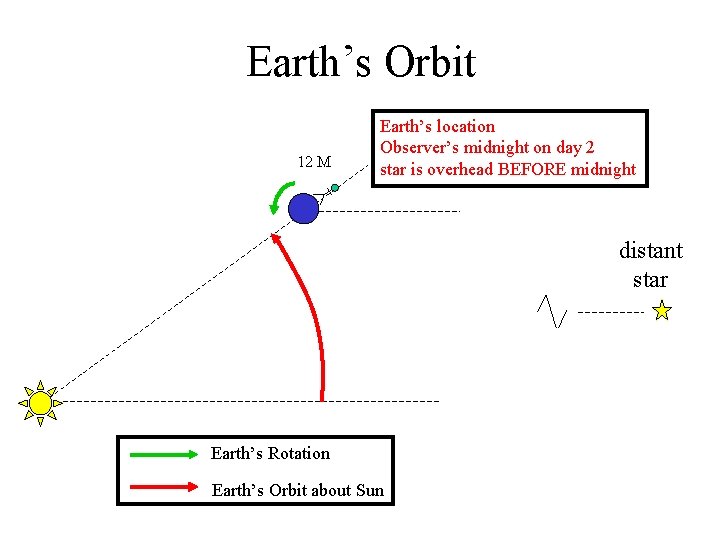
Earth’s Orbit 12 M Earth’s location Observer’s midnight on day 2 star is overhead BEFORE midnight distant star Earth’s Rotation Earth’s Orbit about Sun
Earth’s Orbit 12 M Earth’s location Observer’s midnight on day 2 star is overhead BEFORE midnight distant star 12 N 6 AM Earth’s location Observer’s midnight on day 1 12 M star is overhead AT midnight Earth’s Rotation Earth’s Orbit about Sun
Earth’s Motion Around Sun • Star “on the meridian” at 12: 00 M on December 1 will be “on the meridian” at about: – 11: 56 PM on December 2 – 11: 52 PM on December 3 – 11: 00 PM on December 15 – 10: 00 PM on January 1 • Time when star is at the same point in the sky (rising, on meridian, setting) get earlier by about 1 hour every 2 weeks
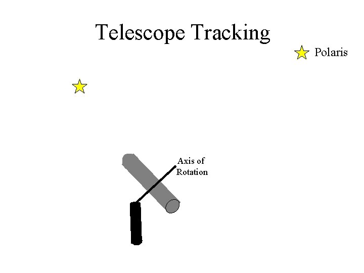
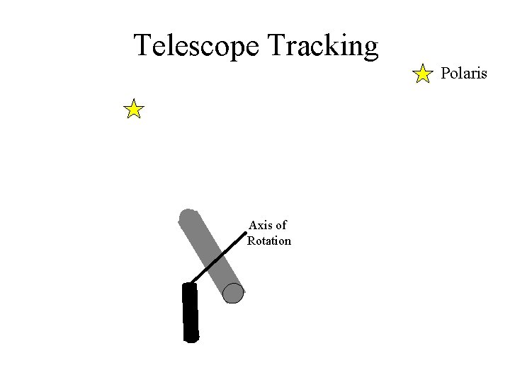
Chief Impact of Earth-Sun Motion on Astronomical Imaging • “diurnal” rotation of Earth requires compensating motion of the camera/telescope to keep the object in the field of view: – camera/telescope moves from East to West – axis of rotation points at celestial pole (at Polaris in northern hemisphere)
Telescope Tracking Polaris Axis of Rotation
Telescope Tracking Polaris Axis of Rotation
Telescope Tracking Polaris Axis of Rotation
Proper Motion of Astronomical Objects • “real” relative motion of object – “proper motion” – generally VERY small except for nearby objects • Moon: 360º in 1 month 12º per day ½º per hour – Moon moves its own diameter in the sky in about one hour – Determines lengths of phases of eclipses • Proper motions of Asteroids and Comets can be large – must be “tracked” to take long-exposure images • Apparent proper motions of planets are quite small • Apparent proper motions of stars (even nearby stars) are very small – but still very measurable!