SIL 211 MEKANIKA TANAH Retaining Wall Design DR


 Pa (Coulomb) 7")


 + (P 2")


- Slides: 34
SIL 211 MEKANIKA TANAH Retaining Wall Design DR. IR. ERIZAL, MAGR DEPARTEMEN TEKNIK SIPIL DAN LINGKUNGAN FAKULTAS TEKNOLOGI PERTANIAN IPB 1
Conventional Retaining Walls Gravity Retaining Structures Stability depends on the self weight of the wall Not economical for design Semi-gravity Retaining Structures Minimum amount of reinforcement may be used in the wall to reduce the size of wall Cantilever Retaining Walls Reinforced concrete is used in wall design with thin stem and slab base Relatively economical for design 2
Conventional Retaining Walls Counterfort/Buttressed Retaining walls Similar to Cantilever retaining walls, but thin slab stems may be used at some interval to tie the base slab and stem in order to reduce the shear force and bending moment for more economical design 3
Retaining Wall Design: Proportioning First, approximate dimensions are chosen for the retaining wall. Then, stability of wall is checked for these dimensions. Section is changed if its undesirable from the stability or economy point of view. Stem Toe Heel 4
Retaining Wall Design: Proportioning 0. 3 m min 5
Earth Pressure on Retaining Wall Earth pressure may be calculated at the vertical section going through the heel of wall. This is under the constraint that Heel is proportioned in such a way that line AC makes an angle less than or equal to h with vertical. 6
Earth Pressure on Retaining Wall Pa (Rankine) Pa (Coulomb) 7
Equivalent Fluid Method Along line AB 1 2 = K Ph h. H’ 2 P v= 1 K v H ’ 2 2 The units of Kh and Kv are the same as (Ph/H 2) Terzaghi and Peck have produced semi-empirical charts for Kh and Kv for different types of soils as listed in the table below 8
9
Retaining walls with backfill slope of finite distance 10
Earth Pressure on Retaining walls with backfill slope of finite distance 11
Earth Pressure on Retaining walls with backfill slope of finite distance 12
Stability of retaining wall OVERTURNING about its toe. BEARING CAPACITY failure of supporting base SLIDING along the base Excessive SETTLEMENT may occur if weak soil layer is located below the foundation within 1. 5 times foundation width. 13
Stability of retaining wall Deep seated shear failure may occur if there is a weak soil layer below the foundation within a depth of about 1. 5 times width of foundation. The failure surface may be assumed to have cylindrical shape and critical failure surface for sliding may be determined through analysis. For back fill with its slope less than 10º, the critical sliding surface may be assumed to pass through heel of the retaining wall. 14
Check Against OVERTURNNG 15
Check Against OVERTURNNG The wall must be safe against overturning about the toe FOS = SM SM R Resisting Moment O Overturning Moment FOS = P av. B+SWi. xi ≥ 2 P ah. ya - P P. yp FOS = 1. 5, if wind/seismic forces are considered Location of Resultant force from toe can determined as (P +SW ). x =SM -SM S M -S M x= P +S W av i R O av i In the design of cantilever retaining wall it is preferred that the stem center is right above the location of resultant force at the base (resultant of soil reaction). 16
Check against SLIDING FOS = SF SF R ≥ 1. 75 S FR = R. tandb +cb. B+ P P FS = P ah FOS = 1. 5, if wind/seismic forces are considered In most cases passive earth pressure is ignored while calculating FOS against sliding Base friction and adhesion may be taken by the following assumption
Alternatives for Improving FOS against Sliding Use base key to increase the passive resistance against sliding Use a Dead man anchor at the stem to transfer a part of sliding force to it. Increase the width of base slab (preferably on heel side) 18
Check for BEARING CAPACITY failure R= (P + S W ) + (P 2 av CE = x = Eccentricity: i ah S M -S M P +S W R O av i e= - P P) 2 B -x 2 For e > B/6, qmin becomes negative, i. e. tensile force. This is not desirable and re-proportioning is required 19
Check for BEARING CAPACITY failure Bearing capacity of soil can be calculated using general bearing capacity equation. qu = c. Nc. sc. dc. ic +q. Nq. sq. dq. iq +0. 5 g. B. Ng. sg. dg. ig Following consideration have to made during the analysis The eccentricity of load on the foundation can be incorporated using effective area method. The bearing capacity is calculated assuming the width of foundation as B' B’ = B-2 e Inclination of resultant force has to taken into account P ah - P P P av +SWi Factor of safety against bearing capacity: FOS = qu qav [ 2 for granular soil 3 for cohesive soils 20
Wall Joints Construction Joints: Vertical or horizontal joints are placed between two successive pour of concrete. To increase shear resistance at the joints, keys may used as shown in the figure below. Contraction Joint: These are vertical joints placed in the wall (from top of base slab to the top of wall) that allow the concrete to shrink without noticeable harm. The groove may be 6 -8 mm wide, 12 -16 mm deep, and they are placed at 8 -12 m spacing. 21
Wall Joints Expansion Joint: These vertical joints are provided in large retaining walls to allow for the expansion of concrete due to temperature changes and they are usually extended from top to bottom of the wall. These joints may be filled with flexible joint fillers. Horizontal reinforcing steel bars running across the stem are continuous through all joints. However, the current thinking is that the large resistance to expansion/contraction on the back face of wall from lateral pressure + the friction resistance of the base, these joints are practically useless. 22
Wall Drainage Accumulation of rain water in the back fill results in its saturation, and thus a considerable increase in the earth pressure acting on the wall. This may eventually lead to unstable conditions. Two of the options to take care of this problem are the following: Provision of weep holes w/o geo-textile on the back-face of wall Perforated pipe draining system with filter Weep hole Filter material Perforated pipe 23
Wall Drainage Vertical drains Weep Holes: They should have a minimum diameter of 10 cm and be adequately spaced depending on the backfill material. Geotextile material or a thin layer of some other filter may be used on the back face of wall for the full height in order to avoid the back fill material entering the weep holes and eventually clogging them. Combination of inclined Inclined drains and horizontal drain for cohesive soils Top drains for clay backfills 24
Wall Drainage Perforated Pipes: These are provided horizontally along the back face of wall at the bottom of stem. The filter material around the perforated pipe should satisfy the following requirements. The soil to be protected should note wash into the filter D 15(Filter) D 85(Backfill) <5 Excessive hydraulic pressure head is not created in the soil due to low permeability. D 15(Filter) D 15(Backfill) >4 25
Wall Settlements Settlement of soil below the wall Immediate settlement in granular soil. Consolidation settlement in cohesive soil. Differential settlement Heel settlement is larger when there is substantial increase in backfill Toe settlements are produced by lateral earth pressure. To minimize toe settlements, ground may be strengthened using sand piles, rock columns, grouting, or structural piles. Differential settlements along the length of wall may produce cracks in the wall. This can be watched during construction itself and preemptive action may be taken such as ensuring proper compaction of the ground. 26
Design of Cantilever Retaining Wall 27
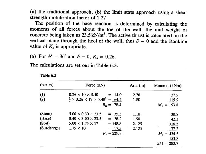
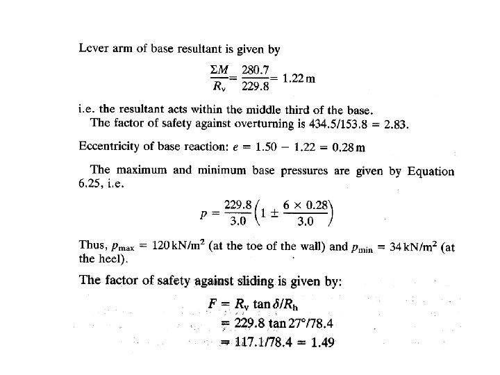
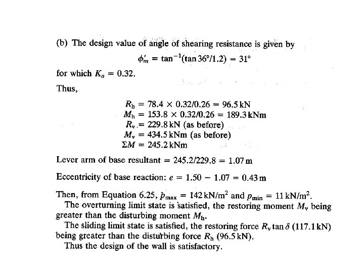
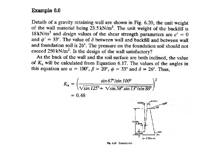
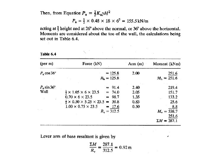
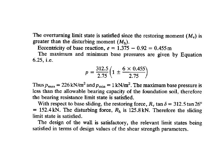
Contoh