Signal Encoding Techniques Topic 8 PhaseShift Keying PSK

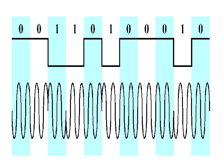
 • Two-level PSK (BPSK) – Uses two phases to represent binary")
")
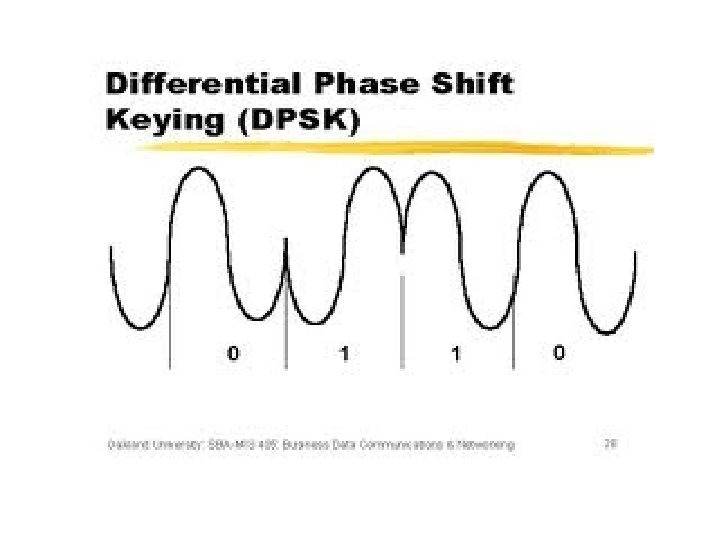
 • Differential PSK (DPSK) – Phase shift with reference to previous")
 More efficient use of bandwidth if each signal element represents more")
")


 –")


 • Signal is broadcast over apparently random series of")
")

")
")
 • Each bit in original signal is represented by")
")

 • In CDMA the users are spread across both frequency")
 • It can provide secure communication in hostile environment such")
 Another application is in multiple access communication in which a")


- Slides: 38
Signal Encoding Techniques Topic 8
Phase-Shift Keying (PSK) • Two-level PSK (BPSK) – Uses two phases to represent binary digits
Phase-Shift Keying (PSK)
Phase-Shift Keying (PSK) • Differential PSK (DPSK) – Phase shift with reference to previous bit • Binary 0 – signal burst of same phase as previous signal burst • Binary 1 – signal burst of opposite phase to previous signal burst
Four-level PSK (QPSK) More efficient use of bandwidth if each signal element represents more than one bit Ø e. g. shifts of /2 (90 o) Ø each signal element represents two bits Ø split input data stream in two & modulate onto the phase of the carrier
Four-level phase Shift Keying (QPSK)
Quadrature Amplitude Modulation • QAM is a combination of ASK and PSK – Two different signals sent simultaneously on the same carrier frequency
Quadrature Amplitude Modulation
Reasons for Analog Modulation • Modulation of digital signals – When only analog transmission facilities are available, digital to analog conversion required • Modulation of analog signals – A higher frequency may be needed for effective transmission – Modulation permits frequency division multiplexing
Basic Encoding Techniques • Analog data to analog signal – Amplitude modulation (AM) – Angle modulation • Frequency modulation (FM) • Phase modulation (PM)
Spread Spectrum
What is Spread Spectrum? ? Definition: q Spread spectrum is a form of wireless communications in which the frequency of the transmitted signal is deliberately varied q. This results in a much greater bandwidth than the signal would have if its frequency were not varied
What is Spread Spectrum? ? Conventional wireless communication: qsignal has a frequency, usually specified in MHz and GHz, that does not change with time (except for small, rapid fluctuations that occur as a result of modulation) q. When you listen to a signal at 103. 1 MHz on an FM stereo receiver, the signal stays at 103. 1 MHz. It does not go up to 105. 1 MHz or down to 99. 1 MHz
What is Spread Spectrum? ? q The digits on the radio's frequency dial stay the same at all times q. The frequency of a conventional wireless signal is kept as constant as the state of the art will permit q. The bandwidth can be kept within certain limits, and so the signal can be easily located by someone who wants to retrieve the information.
Problem with the conventional Communication system There at least two problems with conventional wireless communications that can occur under certain circumstances: q First, a signal whose frequency is constant is subject to catastrophic interference. This occurs when another signal is transmitted on, or very near, the frequency of the desired signal Catastrophic interference can be accidental (as in amateur-radio communications) or it can be deliberate (as in wartime)
Problem with the conventional Communication system q. Second, a constant-frequency signal is easy to intercept, and is therefore not well suited to applications in which information must be kept confidential between the source and destination
Purpose of Spread Spectrum Spread spectrum was originally developed to improve the reliability and security of radio transmissions (primarily for military communications systems). Prior to World War II Spread Spectrum approach to wireless communications is employed today in Wi-Fi and some cellular networks to obtain the following benefits: Enhanced reliability: Mitigates the impact of wireless interference on a communication channel
Purpose of Spread Spectrum Increased Bandwidth: Exploits additional wireless spectrum to better utilize and share bandwidth among multiple channels Improved security: limits the ability of attackers to intercept transmissions The main idea behind spread spectrum is to separate a wireless communication into a set of related transmissions, send the messages over a wide range of radio frequencies, then collect and re-combine signals on the receiving side.
Spread Spectrum q Input is fed into a channel encoder • Produces analog signal with narrow bandwidth q Signal is further modulated using sequence of digits • Spreading code or spreading sequence Generated by pseudonoise, or pseudo-random number generator q Effect of modulation is to increase bandwidth of signal to be transmitted
Spread Spectrum • On receiving end, digit sequence is used to demodulate the spread spectrum signal • Signal is fed into a channel decoder to recover data
Spread Spectrum
Spread Spectrum • What can be gained from apparent waste of spectrum? • Immunity from various kinds of noise and multipath distortion • Can be used for hiding and encrypting signals • Several users can independently use the same higher bandwidth with very little interference
Frequency Hoping Spread Spectrum (FHSS) • Signal is broadcast over apparently random series of radio frequencies (transmitter) • • hopping from frequency to frequency at fixed interval Transmitter operates in one channel at a time Bits are transmitted using some encoding scheme At each successive interval, a new carrier frequency is selected • The sequence of channels used is dictated by a spreading code • A receiver, hopping between frequencies in synchronization with the transmitter • Pick up the message
Frequency Hoping Spread Spectrum • Advantages – Eavesdroppers hear only unintelligible blips (few bits) – Attempts to jam signal on one frequency succeed only at knocking out a few bits
Frequency Hoping Spread Spectrum
Frequency Hopping Spread Spectrum System (Transmitter)
Frequency Hopping Spread Spectrum System (Receiver)
Direct Sequence Spread Spectrum (DSSS) • Each bit in original signal is represented by multiple bits in the transmitted signal • Spreading code spreads signal across a wider frequency band – Spread is in direct proportion to number of bits used – 10 bits spreading code spread the signal across a frequency band that is 10 times greater than a 1 bit spreading code • One technique combines digital information stream with the spreading code bit stream using exclusive. OR • XOR ? ?
Direct Sequence Spread Spectrum (DSSS)
DSSS Using BPSK
Code-Division Multiple Access (CDMA) • In CDMA the users are spread across both frequency and time in the same channel • Unique digital codes, rather than separate RF frequencies or channels are used to differentiate subscribers • The codes are shared by both the mobile stations (cellular phone) and the base station, and are called “pseudo random code sequences” or “pseudo-noise code sequences”.
Code-Division Multiple Access (CDMA) • It can provide secure communication in hostile environment such that the transmitted signal is not easily detected or recognized by unwanted listeners • It can reject interference whether it is the unintentional interference by another user simultaneously attempting to transmit through the channel, or the intentional interference by a hostile transmitter attempting to jam the transmission
Code-Division Multiple Access (CDMA) Another application is in multiple access communication in which a number of independent users can share a common channel without an external synchronizing mechanism
CDMA Example • If k=6 and code is a sequence of 1 s and -1 s – For a ‘ 1’ bit, A sends code as chip pattern • <c 1, c 2, c 3, c 4, c 5, c 6> – For a ‘ 0’ bit, A sends complement of code • <-c 1, -c 2, -c 3, -c 4, -c 5, -c 6> • Receiver knows sender’s code and performs electronic decode function • <d 1, d 2, d 3, d 4, d 5, d 6> = received chip pattern • <c 1, c 2, c 3, c 4, c 5, c 6> = sender’s code
CDMA Example • User A code = <1, – 1, 1> – To send a 1 bit = <1, – 1, 1> – To send a 0 bit = <– 1, 1, 1, – 1> • User B code = <1, 1, – 1, 1, 1> – To send a 1 bit = <1, 1, – 1, 1, 1> • Receiver receiving with A’s code – (A’s code) x (received chip pattern) • User A ‘ 1’ bit: 6 -> 1 • User A ‘ 0’ bit: -6 -> 0 • User B ‘ 1’ bit: 0 -> unwanted signal ignored
Example If A sends a 1 bit, then d is <1, -1, 1> and the preceding computation using SA becomes. If A sends a 0 bit that corresponds to d=<-1, 1, 1, -1, 1, >, we get if user B is sending and we try to receive it with SA, that is, we are decoding with the wrong code, A's.