SIEMENS PROGRAMMING TRAINING SIPLACE PRO DESK SIPLACE Pro

")
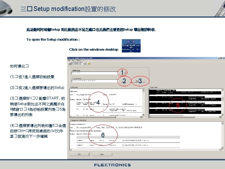
� Starting the SIPLACE PRO DESK 以鼠標點擊 在屏幕上顯示如圖 1_1")
� Overview of the use interface 1 2 4 3 5 6 (1). Menu")
 Menu Bar In the menu bar , all functions can be called by")
 Product objects 1� About production program function at these menus. 有關生產程序的編輯功能都在這些菜單里。 Components (BE)")


 Equipment view About the machine equipment and the station editor and the lines")
 Properties Use the symbol Properties Window. to show the properties of the object")
 The Tab controls In the tab controls , there is additional , or")
 creating new objects (創建新目標) You have the option of using a specific editor")
 Change Language In the menu Tools Change Language you have the option")
 Settings In the menu Tools Settings you have the option to establish")

� Line computer import wizard call as follows : menu")


� RT Import Call as follows : Menu bar : Tools Import")
� CAD data import wizard Call using : Menu bar : Toolbar Tools Import")
� ASCII centroid data import wizard Call using : Menu bas : Tools")


 Gerber data import wizard Call as follows : Menu bar : Tool Import")
 Data Model Import Call as follows : Menus bar : Tools Import")
 Line Computer export wizard Call as follows : Menu")
 Data Model Export Call as follows : Select the object or folder in")
")
� The component shape (GF) 1� GF Library When SIPLACE Pro is installed then")

 Component shape wizard When in the standard library no find GF we will")


 Component shape editor 1� Main view/properties In the figure below you see the")


 The component shape difference editor wizard helps you to compare two component shapes.")

")
 Component editor The component editor is used to create and modify component objects")


 Fiducial wizard Call as follows : Menu bar : Tools Fiducial wizard")


� General - In SIPLACE Pro the table containing the placement position")


 � General - The PCB editor can be used to program")
 Ink spots on a board Ink spots are used to prevent components from")
 Create a new board Board To create a new board : Menu bar")

 The Station Editor To create a new station : Menu bar : Toolbar")
 The Line Editor In order to work configured placement station , you must")

 General - Feeders and nozzle can be found among “plant Overview” in the")


� cycle time 循環時間 以秒為單位 (2)�")


 General -- Recipes are central in SIPLACE Pro. -- The recipe is the")
 Recipes To open a recipe : Click “My Recipe” in the Tree control,")

 General -- In the download operation. The programmed data is checked for integrity")
 How to download the program Click the “Recipe” in the Line Control GUI")


- Slides: 131
SIEMENS PROGRAMMING TRAINING SIPLACE PRO DESK 培訓手冊
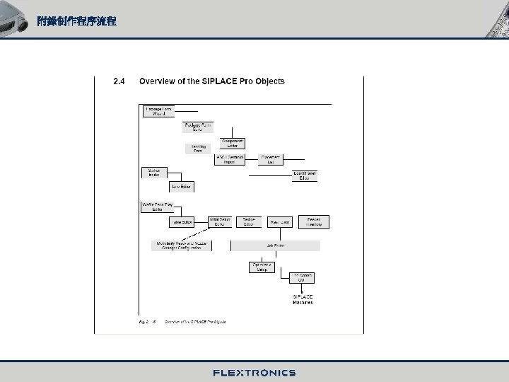
一� SIPLACE Pro Software Overview 二� Import and Export Functions 三� Component Shapes (GF) 四� Component (BE) 五� Fiducials 六� Placement lists 七� Boards 八� Station and Line 九� Feeder and Nozzle 十� Setup 十一� Component packages and Waffle-pack Trays 十二� Jobs and Optimization 十三� Recipes 十四� Download
一� SIPLACE PRO Software Overview (一)� Starting the SIPLACE PRO DESK 以鼠標點擊 在屏幕上顯示如圖 1_1 SIPLACE PRO is starting 1_1 1
(二)� Overview of the use interface 1 2 4 3 5 6 (1). Menu bar主菜單欄 (2) Symbol bar 具欄 (3) Tree controls of the product objects 樹型目錄模式 (4) Display area/window 顯示 窗口 (5) Symbol bar of the editors in the display area 圖型 具欄(用 于編輯) (6) Tree controls of the production Objects (樹型目錄模 式) (7) Status bar 狀態欄 (8) Tab control 表格控制欄 7 8 2
(三) Menu Bar In the menu bar , all functions can be called by pop-up menus. 所有的功能都可以在主菜單欄里彈出 (四) Symbol Bar The symbol bar shows the function that you will use the most often. 在 具欄里列有一些最常用的功能 View of equipment 查看機器裝配及有關 機器的編輯 View product overview 查看生產程序及生產程序編 程 Change units of measurement 度量單位轉換 Wizards 導入導出向導 Zoon functions 放大� 小功能 3
(五) Product objects 1� About production program function at these menus. 有關生產程序的編輯功能都在這些菜單里。 Components (BE) 元件 Component shape (GF) 元件形狀 Fiducial 基准位置 Placement list 貼片列表 Boards (PCB) 印刷板 Tables 料台 Setups 排料設置及生產線的 初始設置 Recipe (job) 作列表 Jobs (Optimization) 作優化器 4
2� Tree structure menu In the example you see a component OT 0402_1 that is assigned to Package from 100. Tree structure of component OT 0402_1 On the tree structure will display the feeder , camera and nozzles that were assigned to the component. 5
3� In the tree controls Press right mouse key , the window display the menu You can creating a new folder , view alias list , etc. 別名目錄 建立文件夾 6
4� Deleting a folder or an object in the tree controls Mark the folder or object and press Del key on the keyboard. 注意� 有兩種情況不能刪除. 1� 當文件夾里有文件時不能. 2� 當某一文件里用到該數據時不能 DELETE 5� Data Management SIPLACE Pro offers the possibility to copy , to delete or to rename object in the tree controls. This is performed by means of the function Multi Select in the context menu of the right mouse key. Right mouse key : Multi_ Select 在此對話框可進行拷貝� 移動� 刪除等功能 7
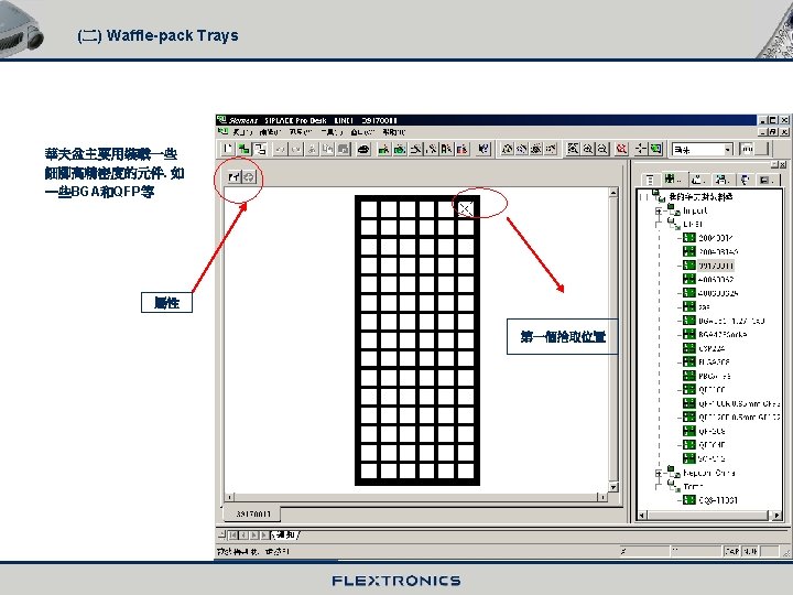
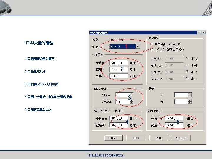
(六) Equipment view About the machine equipment and the station editor and the lines create. 有關機器的裝配和站台的編輯以及生產線的建立。 Feeder types 喂料器 Waffle pack trays 華夫盤 Stations 站台 Lines 生產線 Nozzles 吸咀 Component packages 元件包裝 8
(七) Properties Use the symbol Properties Window. to show the properties of the object which is marked in the 點擊屬性這一圖標顯示一個對話框 可對這些數據進行編輯 Ways to close an object or dialog window 關閉對話框 9
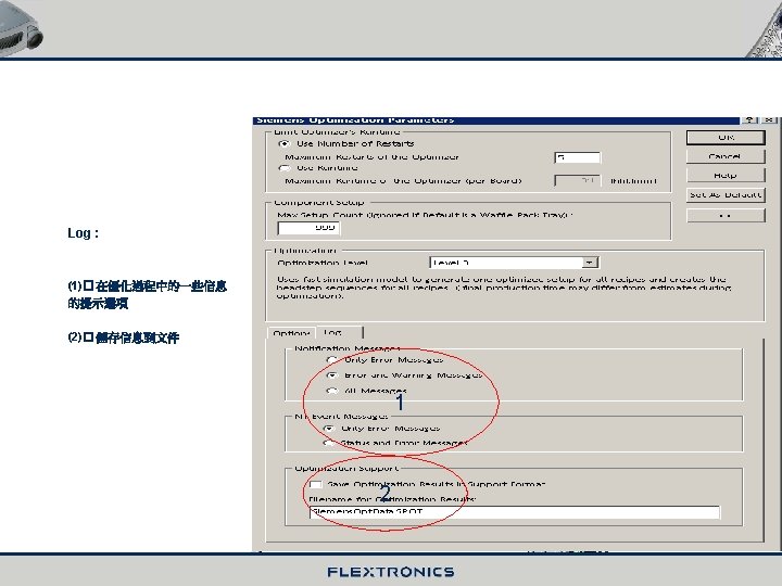
(八) The Tab controls In the tab controls , there is additional , or alternatively supplemental information for the editor’s Properties dialog in the work area. Lists- the placement list for example – are display and edited in tab control. NOTIFICATION information about the import/export function is show in tab control as well as error Messages. 這是對編輯屬性的一個追加功能 � 在貼片列表里就是一個例子� 它顯示和編輯都在支配欄里. 通知欄顯示一些錯誤的信息 Deleting a lead Adding a lead group Notification Geometrical data Selection of the group to be displayed 10
(九) creating new objects (創建新目標) You have the option of using a specific editor to create and edit new objects such as new boards , new package forms , etc. Additionally, you can create new directories. You will be given a choice of all possible objects to choose from (see picture). 使用一個特有的編輯器去創建和編輯新目標如� NEW broad, new package 等. 可在這些目標中選擇(如圖) 如何運行� Menu bar : ItemNEW Symbol bar : Keyboard : Ctrl+N Tree control : right mouse key -----context menu 11
(十) Change Language In the menu Tools Change Language you have the option of changing the language of the user Interface. After calling it , the following dialog accessing. appears. The following dialog will be displayed after 改變界面的語言一般都有几種供選擇. 默認的是英語。 Regardless of the current language , The list is always displayed in English 不管當前是何語言列 表里顯示的總是英語 12
(十一) Settings In the menu Tools Settings you have the option to establish general settings and functional defaults. 在設置里可進行基本設置和功能的缺省值 Software Version of the UNIX Line Computer and path to the master data directory UNIX Line computer 軟件版本和主要數據的路徑 13
二� Import and Export Functions
1� The import wizard (一)� Line computer import wizard call as follows : menu bar : Tools Import Line computer import wizard …. . This wizard allows you to import the master data of the Line computer into SIPLACE Pro. 路徑 注意� 要從Line computer 里 導入或導出數據時一定確認PRO 與 UNIX 是聯網的. 而在導入之前 � 要在PRO里連接到UNIX里的 數據, 使其顯示在PRO里。具體方 法如下� (1)� My ComputerTools map Network Drive…folder 在此輸入Line computer IP地 址按Finish. (2)� 進入如圖向導里� 在 Line computer 版本那里要打勾說明 可以在 404或以上的版本適用. (3)� 給出導入路徑后點 Next. Line computer 的 版本在 404或以上 14
Line Computer Import wizard The data to be import by the line computer ( component shapes , components and printed circuit boards ) please choose the Component number press Next 15
Line Computer Import wizard The window display the GF number in this dialog Press Select All and Next. The window will be display the component and printed circuit boards. 在此窗口顯示全部的GF. 按選擇全部 被選的會變藍色. 然后按下一步. 再下一 對話框將依次提示你選擇元件和PCB, 如選擇將全部導入PRO里。 16
Line Computer Import wizard The setup information , fiducial information And vision data of the component shapes. 這一步有三個選項提示是否導入Pro 里 選擇完 按Finish 等待一頓時間把數據導入pro . 注 : SST 文件是GF的照相數據 17
(二)� RT Import Call as follows : Menu bar : Tools Import RT Import This wizard allows you to import external setup files into SIPLACE Pro from the Line computer. 此向導是把 LINE Computer 的 Setup 導入SIPLACE Pro. 在導入setup 時� 首先要有一條與Line Computer 里一樣的 生產線。 必須是RT文件 18
(三)� CAD data import wizard Call using : Menu bar : Toolbar Tools Import CAD Data Import wizard … : This wizard allows you to import native CAD files directly into SIPLACE Pro. NOTE This wizard starts the CAD converter , which is available as an option. 此向導把CAD 導入PRO里� 但需借助一些 軟件支持� 一般較少用 19
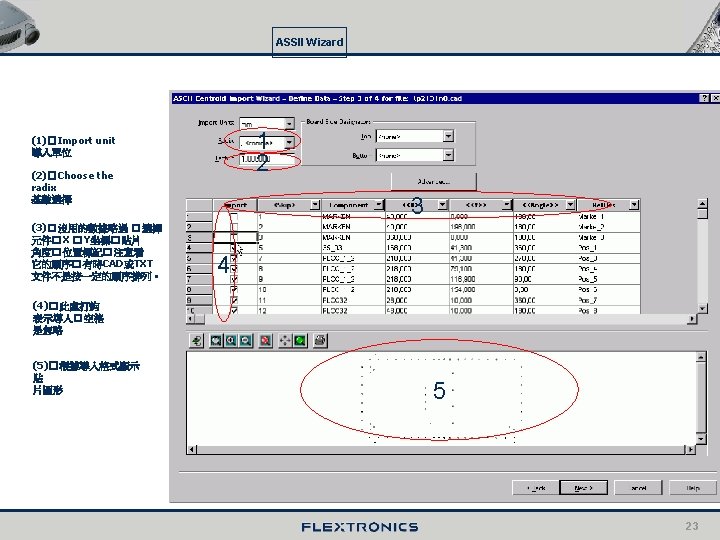
(四)� ASCII centroid data import wizard Call using : Menu bas : Tools Import ASCII Centroid Data Import wizard… Toolbar : This wizard is used to create a placement list in SIPLACE Pro 此向導把一個貼片列表導入Pro 里. 導入的文件類型為. cad 和. txt *. cad或*. txt文件 20
ASSII Wizard Select a format that is compatible with the ASCII file , if there is one , or generate a new format. If you select a compatible format , it simplifies the following steps. 選擇一個導入 格式或新建一個 格式進行導入。如果選擇一個 可兼容的格式� 就更簡單。 Select a format 21
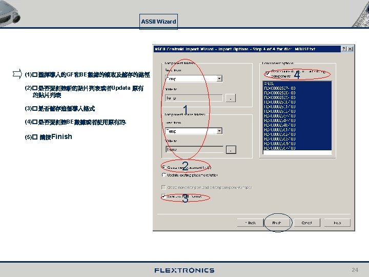
ASSII Wizard Select record and field delimiters and Illegal characters 此步驟選擇一個檔案格式和分界以 及處理一些非法符號 22
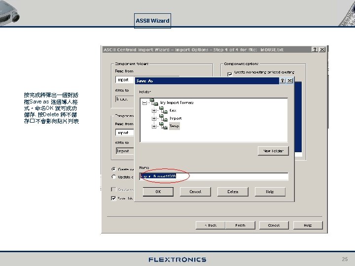
ASSII Wizard The result of the import is a new placement list , which is displayed in the placement list editor. Save the placement list by choosing the Object / Rename As … menu command. 26
(五) Gerber data import wizard Call as follows : Menu bar : Tool Import Gerber file Import wizard Toolbar : This wizard is import Gerber data into SIPLACE Pro , Which you can then use for printed circuit board. . Only the RS 274 x data format is supported 這向導把Gerber 文件導入SIPLACE Pro. 一般的Gerber 數據不 能直接導入�需要借助另外的軟件支持. RS 274 x 除外. Gerber file import dialog 27
(六) Data Model Import Call as follows : Menus bar : Tools Import Data Model Import Note : By means of the Data Model import/export it is possible to move SIPLACE Pro objects (component shapes , boards …) from a SIPLACE Pro system to another one. 使用這種手法主要是在Pro 與 Pro 之間的數據交換。 These objects must be existing in the “. xml” format 導入處的文件類型是 “*. xml” Data model import 28
2� The export wizard (一) Line Computer export wizard Call as follows : Menu bar : Tools Export Line computer Export wizard … 此向導是把SIPLACE Pro 的數據導出到 Line Computer 或者其它一些媒體數據庫. 可把Pro 里的 GF. LA. BE 導出 � 在導出時 注意Line Computer 所用的版本 路徑 Software version V 402 to V 503 of the Unix line computer 適用版本為 V 402到 V 503 或更高的 29
(二) Data Model Export Call as follows : Select the object or folder in the tree control area. Menu bar : Tools Export Data Model export… 數據導出向導主要是對數據的備份以及用于 其它的SIPLACE Pro 里. 具體操作為選中 一個要導出的文件按鼠標右鍵彈出Data Model export 點擊顯示如下對話框提示命 名 30
三� Component Shapes (GF)
(一)� The component shape (GF) 1� GF Library When SIPLACE Pro is installed then a collection of master data is also automatically. Use the line Computer import wizard to import this data into SIPLACE Pro. 剛安裝的SIPLACE Pro 里是沒有GF的� 它以UNIX的方式儲存在下圖畫紅圈的文檔里� 所以要用Line computer 導入向導把它導入 SIPLACE Pro desk 里。 GF Library Target directory following a standard installation 31
2� Import the standard GF The siemens standard GF from library so will use the line computer import wizard to import it. press the Line computer import wizard beginning to Import. The process way to see the “二 (一) 1� The Line Computer Import wizard. 32
(二) Component shape wizard When in the standard library no find GF we will create a new component shape by choosing the New function from the menu bar or toolbar. But it is much quicker and simpler to use the Component shape wizard. Choose the object press the OK to the next dialog. Menu bar : Tools component shape wizard Toolbar: Selection category “Integrated Circuits” 芯片類 Selection category “Dual Lead” 雙引線類 33
Component shape wizard Selection of the lead type Entry of geometric dimensions 34
Component shape wizard Enter the lead number press Finish. 35
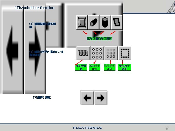
(三) Component shape editor 1� Main view/properties In the figure below you see the main view of the component shape editor. At the tree structure of Component Shape Tem Selection you want to editor the GF display this Dialog 1 2 (1)� properties (2)� Display package form (3)� 元件形狀選擇 (4)� 編輯元件外形及偏差 3 6 4 (5 -6)� 選擇一個引腳組進行編 輯包括 Pitch� 引腳個數及大小 � 類型 5 36
Properties The Properties menu allows you to enter the data show in the figure below 在屬性里可以對一些數據進行編輯� 如Body size � Body offset� Lead Group tolerance 等. 注意在 “Line computer Equivalent” 與它同等的名字� 這里與你命名的最好一致. 在使用component Shape wizard 創建GF時會有一個默認的名字. (1)� 墨點的設置 1 (2)� 元件的描述 (3)� 編輯元件顏色 (4)� 與Line computer 同等名 2 3 4 37
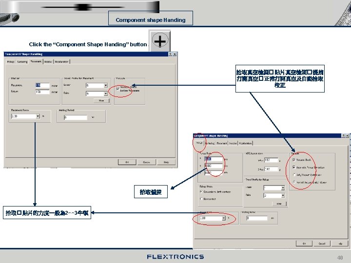
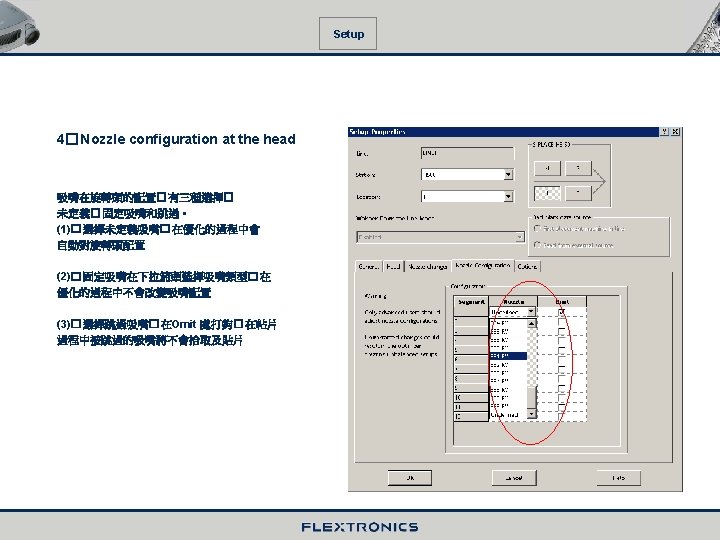
3� Component shape handing Click the “Nozzle “ button Tip: , select a head type , and enable individual nozzle and the corresponding cameras. Make sure that all cameras which are not used in your lines are switched off in order to avoid errors during optimization. (1)� 選擇機器旋轉頭類型 (2)� 選擇元件適用的吸嘴此同時給你自動配 上 相機 5 (3)� 根據機器相機選擇類型如果自動配的吸 嘴 不符可把它關閉. (4)� 元件拾取角度 0~~90度 (5)� 拉下此對話框可看到所選吸嘴是否符合 然后再進行選擇 3 1 2 4 39
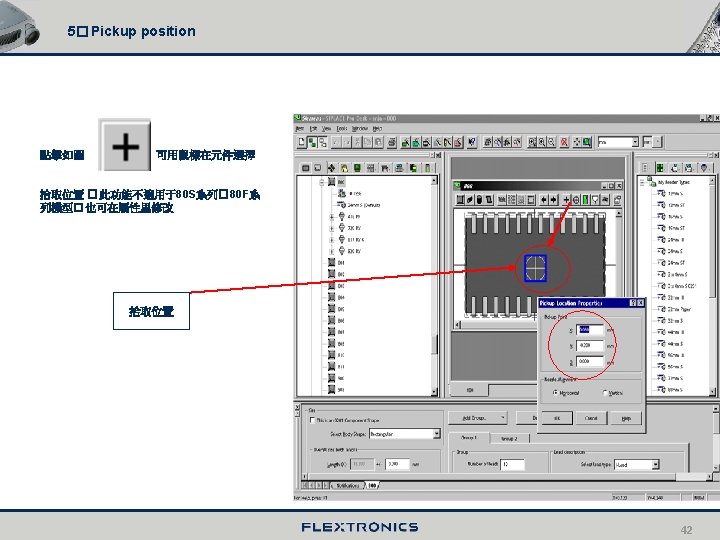
4� Feeder assignment Click the “Feeder” button , and assign the component shape the feeder type . 1 3 (1)� 元件包裝選擇 2 (2)� 拾取偏差和包裝公差 (3)� 默認feeder, 如要更換按Add 選擇類型 (4)� 等待時間� 針對一些料的拾取效果 4 41
(四) The component shape difference editor wizard helps you to compare two component shapes. Start the wizard. MENU bar / Tools Difference Editor wizard or Toolbar : click the button , Select the two directories containing the component shapes you want to compare Select the component shape to be compared. 44
Difference compare Now compare the data they contain in detail. Note The rows that appear in red indicate differences. 45
四� Components (BE)
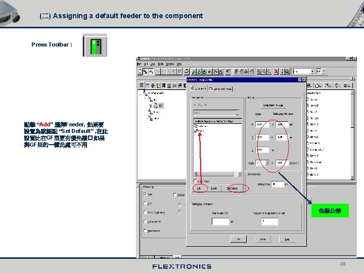
(一) Component editor The component editor is used to create and modify component objects manually. All the component’s Parameters can subsequently be modified. 此編輯可創建新元件和修改元件的參數� 在菜單里點擊New component 或者使用快截鍵 就可彈出如 圖。 3 (1)� 條形碼創建 (2)� 關聯GF從此入 (3)� Feeder 的關聯� 在此 處配置Feeder 優先 1 2 46
Component shape selection Selection the GF number Press OK 47
五� Fiducials
(一) Fiducial wizard Call as follows : Menu bar : Tools Fiducial wizard Toolbar : Choose the fiducial objects press Next 49
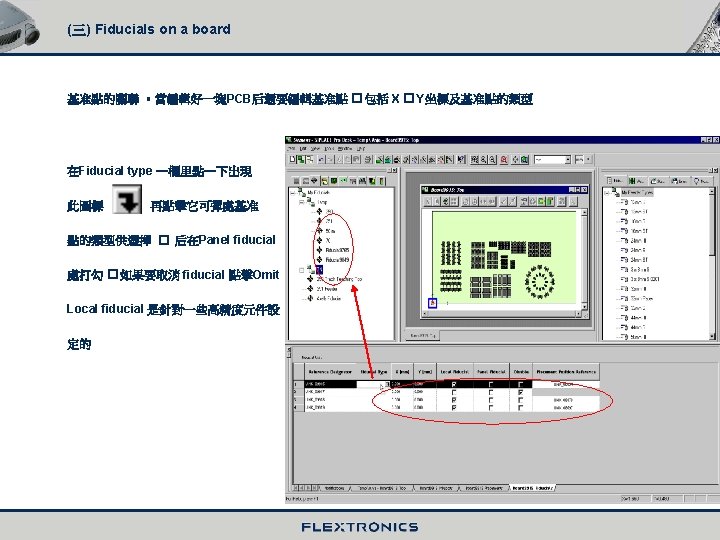
The fiducial Please enter the fiducial size and choose the color. Click Finish 在這里的基准點的顏色以站台里示教的 為准. 50
The fiducial . SIPLACE Pro then displays the fiducial Click the Properties button The fiducial can be edited in the “Properties” dialog box. 51
六� Placement Lists
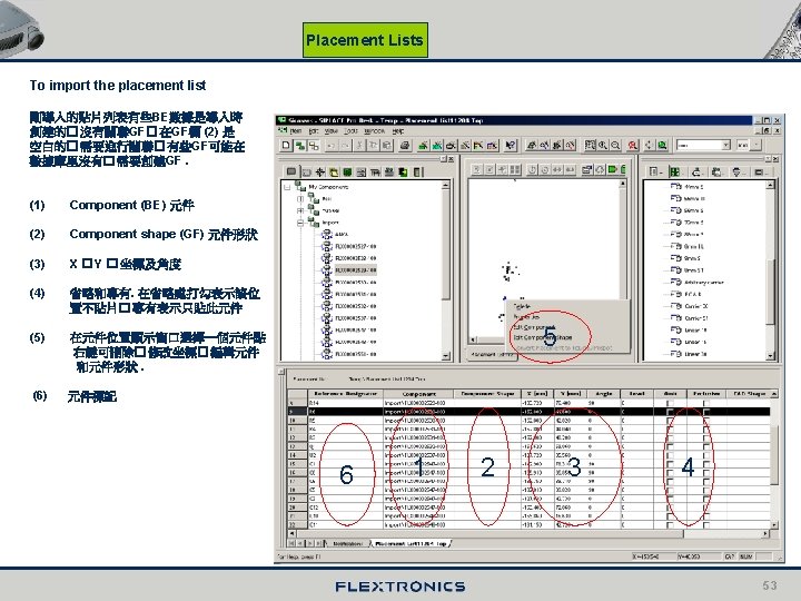
Placement Lists (一)� General - In SIPLACE Pro the table containing the placement position is stored separately rather than in the printed circuit board. This object is the placement list. - A placement list can be assigned to any PCB or side of a PCB (e. g. by drag and drop ). - You can create a placement list either manually ( in the placement list editor ) or by importing data ( ASCII centroid data import , CAD import ). - You can use the placement list editor to edit a placement list at any time. (二) Placement list editor To create a new placement list : Menu bar : Object New Placement List Toolbar: Placement List Note : 用手 創建一個貼片列表比較麻煩� X� Y data 都用一個個輸進去. 使用 ASSII Data import 導入的方法更加快截. 具體如何導入請參考( 二 (四) � ASSII import ) 52
Placement Lists To open an existing placement list : - Via the context menu : Right mouse button --- Click the placement list in the Tree Controls , and choose “Open” from the context menu. Alternatively , double-click the placement list in the Tree Controls. 54
七� Boards
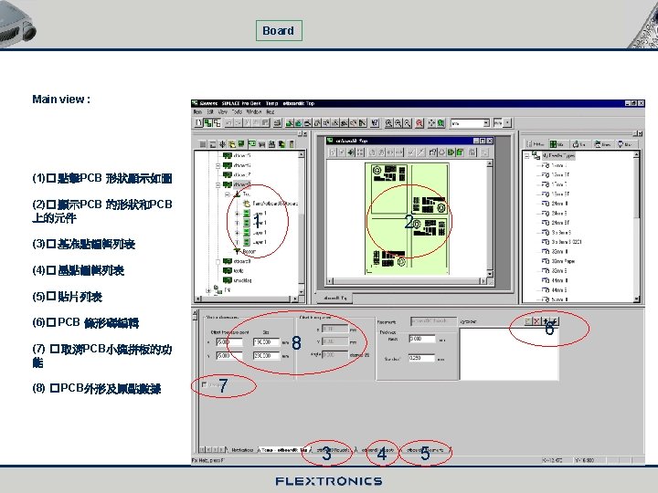
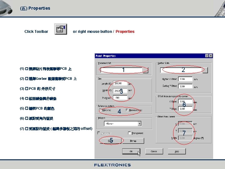
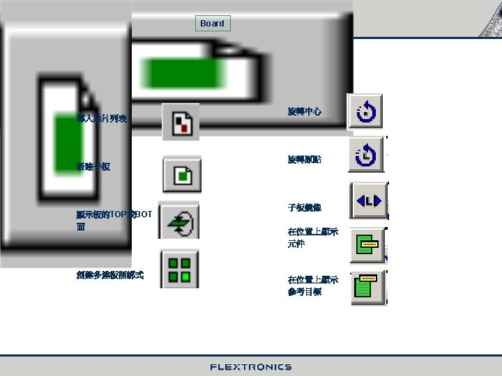
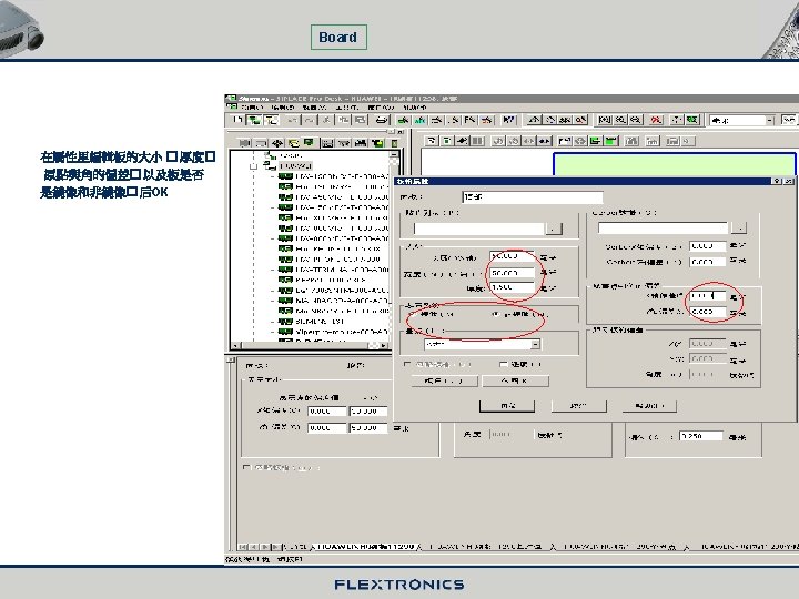
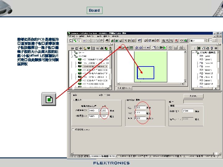
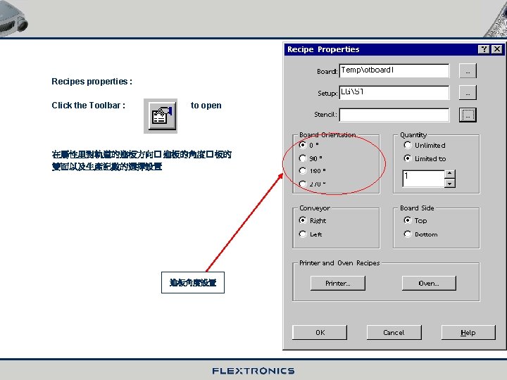
Board (一 ) � General - The PCB editor can be used to program single- and multicluster- PCB structures. - In SIPLACE Pro a PCB always has a top side and a bottom side. Different placement lists can be assigned to the two sides. You can switch between the two sides with a mouse click. ( 二 ) � Board editor 1� Main window To open an existing board : - Via the context menu : Right mouse button --- click the board in the Tree controls , and choose “Open” from the context menu. - Alternatively , double-click the board in the Tree controls. In the figure below you can see the board editor’s main window.
(四) Ink spots on a board Ink spots are used to prevent components from being placed on cluster-panel boards with sub-panels that have defects. For that purpose the ink spot must be taught at the station first. During the Placement process. Depending on the result of ink spot recognition , sub-panels are omitted possibly. 墨點的設置與基准點一樣. 靠機器光學對中 � 處理 來識別
(七) Create a new board Board To create a new board : Menu bar : Object New Board Toolbar 選擇新建印刷板顯示如圖 : Board or click right mouse on tree control of board choose New board
八� Stations and Lines
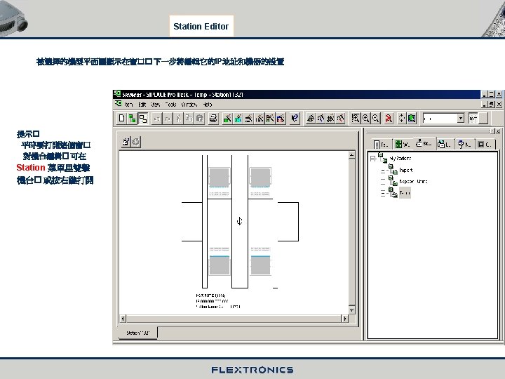
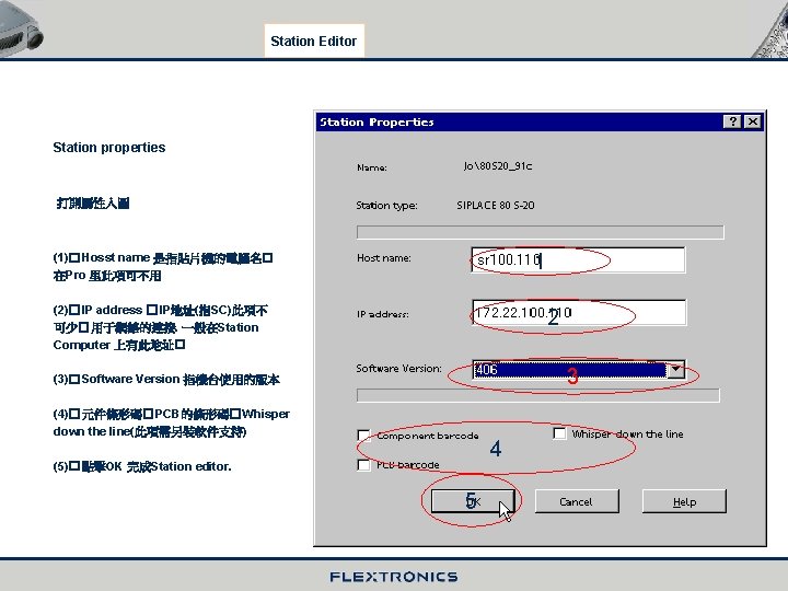
(一) The Station Editor To create a new station : Menu bar : Toolbar : Object New Station Note : 當要創建一個機台時� 首先去選擇機台的類型� 按OK.
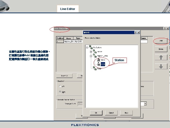
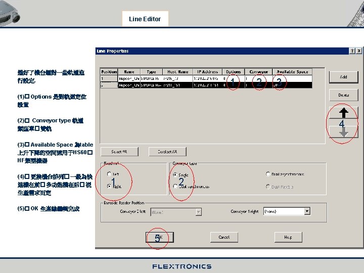
(二) The Line Editor In order to work configured placement station , you must first combine them to form a line. To create a new line : Menu bar : object New Line Toolbar : New Line click right mouse
九� Feeder and Nozzle
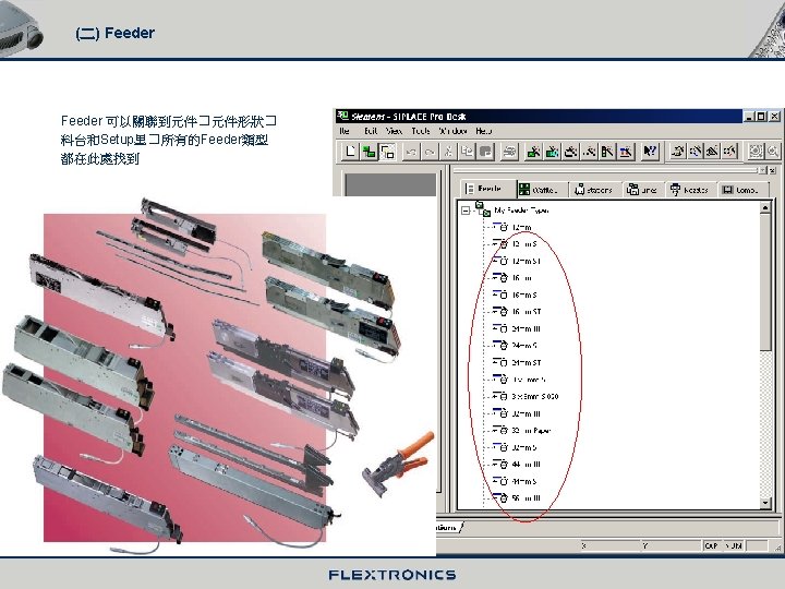
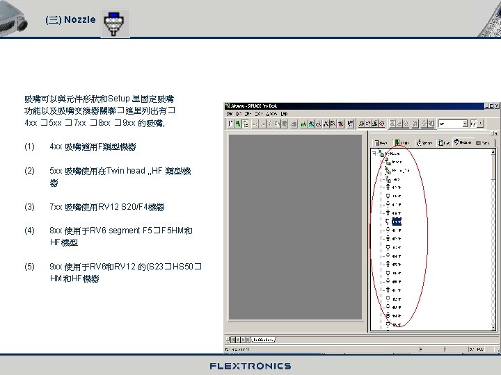
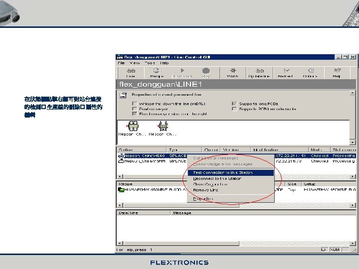
(一) General - Feeders and nozzle can be found among “plant Overview” in the Tree Controls. - Whereas feeders and standard nozzle cannot be changed , customer-specific nozzle are programmable. -Feeders and nozzle can be assigned to other objects at the appropriate points. This can be done , for example. By: - Drag & drop from the Tree Controls - Using options available in the editors ( buttons and the context menu , which you access by means of a right-click) 標准的Feeder 和吸嘴是不能更改的. 但可以設計特殊的吸嘴� 可以用拖拉的方法把Feeder 和吸嘴 關聯到認可的目標上
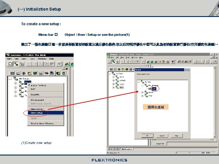
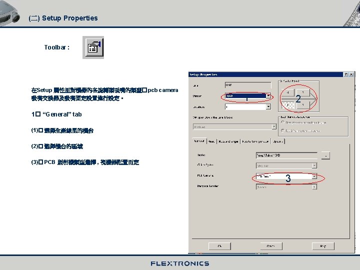
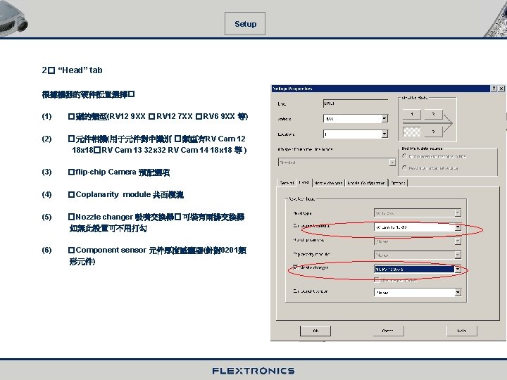
十� Setup
十一� Component Packages and Waffle-pack Trays
十二� Jobs and Optimization
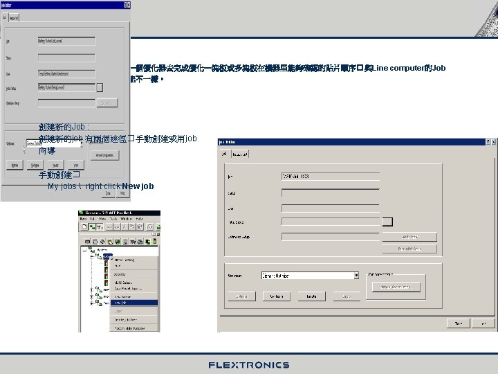
Job wizard : Menu bar : Tools Job Wizard … Toolbar : when the screen display the “Welcome to the Job Wizard” please click “Next”
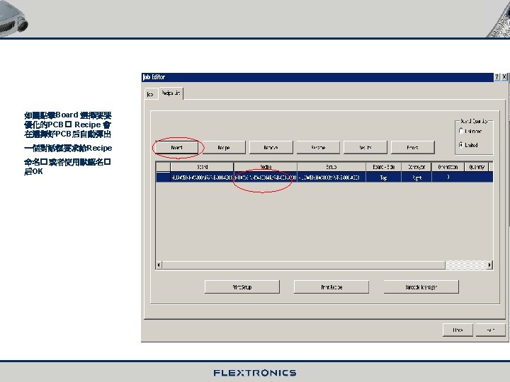
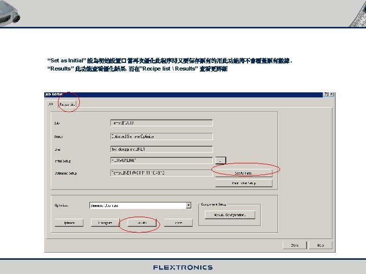
儲存Recipe
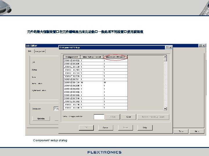
To open the Results : In production Time (1)� cycle time 循環時間 以秒為單位 (2)� Placement 貼片個數 (3)� Head cycle 旋轉頭循環次數 (4)� 每個旋轉每小時貼片個數 1 2 3 4
In the Nozzle Configuration 顯示每個旋轉頭的吸嘴配置
十三� Recipes
(一) General -- Recipes are central in SIPLACE Pro. -- The recipe is the object that is sent to the line by download , so it must contain all the data. -- In the recipe , a Single board is combined with a setup. Only if a Dual Synchronous Conveyor is used the recipe contains a second board. -- There is a lot of other data behind the board (cluster data , placement list , components , component shape and fiducials ), and the setup stands for the station and line configuration, feeders , waffle pack trays , nozzle and result of optimization. -- The recipe also contains other data such as the board side , the position of the board in the conveyor system , the conveyor track and the quantity of boards to produce.
(二) Recipes To open a recipe : Click “My Recipe” in the Tree control, choose a object double-click be opened. All the data in the recipe (1)� PCB 在傳送軌道上 1 (2)� Setup 1 2
十四� Download
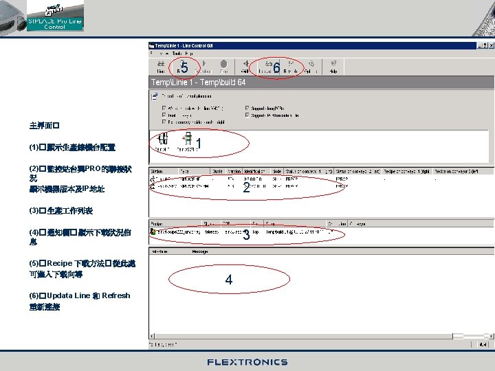
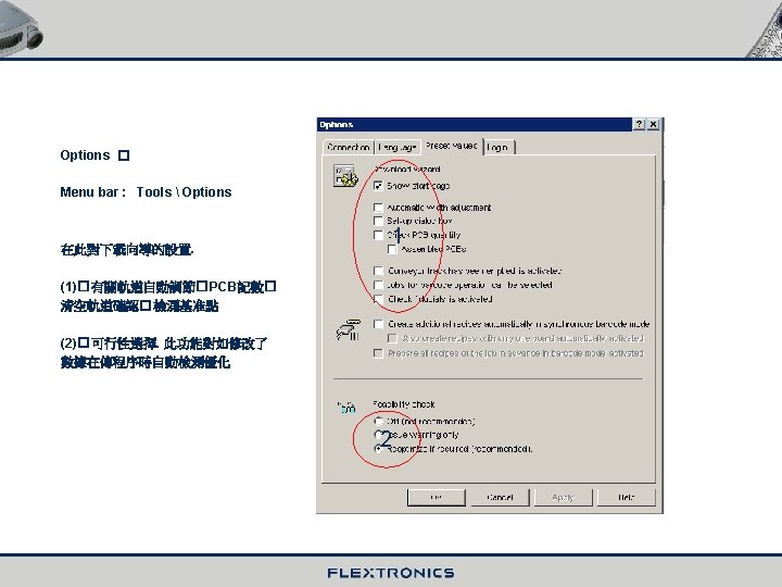
(一) General -- In the download operation. The programmed data is checked for integrity and then set to a selected line. -- Each station receives the production data that was generated for it during optimization. -- The download object is the recipe. It contains all the relevant information. -- If data that goes into the recipe has been changed since the last download. This is recognized during the download , and the data is optimized or adapted ( feasibility check, calculation of the head steps ) -- The reason for this may be , for example , that a placement angle has changed. -- The download is carried out with the help of a separate application , the Line Control GUI ( Graphical User Interface). (二) Line Control GUI SIPLACE Pro menu bar : Button on the windows desktop : Tools Line Control GUI
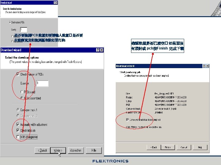
(三) How to download the program Click the “Recipe” in the Line Control GUI main window. Display the welcome dialog , and click Next. Welcome dialog 選擇一個 生產程序進入下一步
TOOLS
The End Thanks !