
Shielding of the SPS Vacuum Flanges Design Studies

- Slides: 18
Shielding of the SPS Vacuum Flanges - Design Studies – Update Jose E. Varela and Jaime Perez 21 May 2015
Outline • Introduction • Vacuum Flange Shielding Studies – New Reference – Tube & Double Tube – Pumping Port Fingers – Gap Filling • Shield Comparison – R/Q Reduction • Next Steps
Introduction Today we report on the progress made in the design of suitable shields for vacuum flanges belonging to group II. This presentation will not cover the redesign of the bellows belonging to group II (production of elliptical bellows) nor the impedance reduction measures for flanges belonging to group I (QD flanges). More information can be found in previous presentations [LIU-SPS BD WG meetings on 09 -102014, 04 -09 -2014 and 12 -03 -2015]
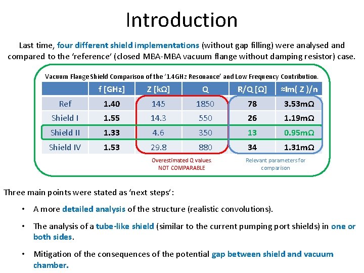
Introduction Last time, four different shield implementations (without gap filling) were analysed and compared to the ‘reference’ (closed MBA-MBA vacuum flange without damping resistor) case. Vacuum Flange Shield Comparison of the ‘ 1. 4 GHz Resonance’ and Low Frequency Contribution. f [GHz] Z [kΩ] Q R/Q [Ω] ≈Im( Z )/n Ref 1. 40 145 1850 78 3. 53 mΩ Shield I 1. 55 14. 3 550 26 1. 19 mΩ Shield II 1. 33 4. 6 350 13 0. 95 mΩ Shield IV 1. 53 29. 8 880 34 1. 31 mΩ Overestimated Q values. NOT COMPARABLE Relevant parameters for comparison Three main points were stated as ‘next steps’: • A more detailed analysis of the structure (realistic convolutions). • The analysis of a tube-like shield (similar to the current pumping port shields) in one or both sides. • Mitigation of the consequences of the potential gap between shield and vacuum chamber.
Outline • Introduction • Vacuum Flange Shielding Studies – New Reference – Tube & Double Tube – Pumping Port Fingers – Gap Filling • Shield Comparison – R/Q Reduction • Next Steps
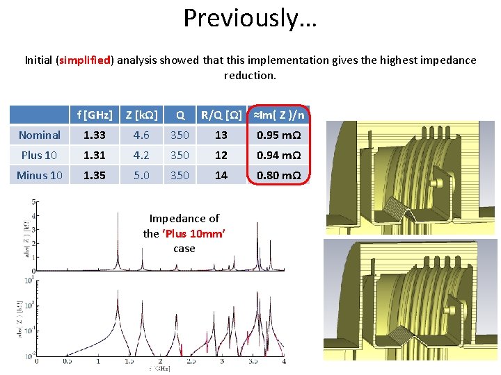
Previously… Initial (simplified) analysis showed that this implementation gives the highest impedance reduction. f [GHz] Z [kΩ] Q R/Q [Ω] ≈Im( Z )/n Nominal 1. 33 4. 6 350 13 0. 95 mΩ Plus 10 1. 31 4. 2 350 12 0. 94 mΩ Minus 10 1. 35 5. 0 350 14 0. 80 mΩ Impedance of the ‘Plus 10 mm’ case
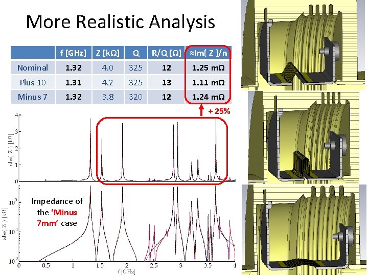
More Realistic Analysis f [GHz] Z [kΩ] Q R/Q [Ω] ≈Im( Z )/n Nominal 1. 32 4. 0 325 12 1. 25 mΩ Plus 10 1. 31 4. 2 325 13 1. 11 mΩ Minus 7 1. 32 3. 8 320 12 1. 24 mΩ + 25% Impedance of the ‘Minus 7 mm’ case
Outline • Introduction • Vacuum Flange Shielding Studies – New Reference – Tube & Double Tube – Pumping Port Fingers – Gap Filling • Shield Comparison – R/Q Reduction • Next Steps
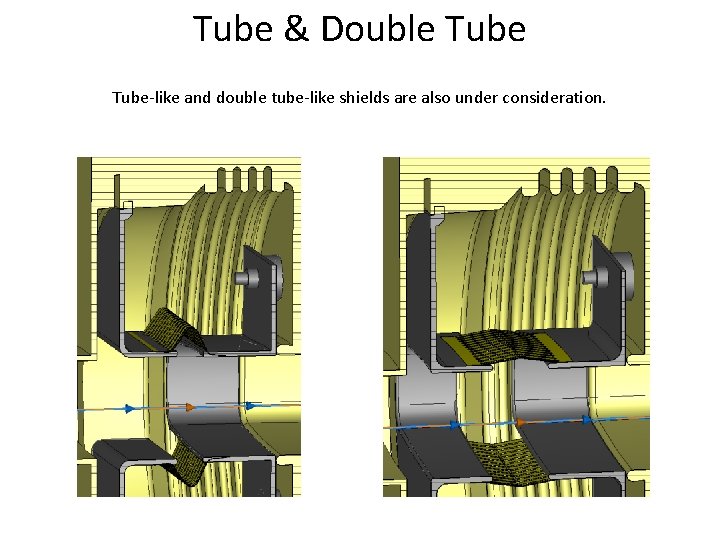
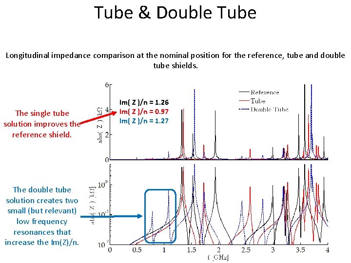
Tube & Double Tube-like and double tube-like shields are also under consideration.
Tube & Double Tube Longitudinal impedance comparison at the nominal position for the reference, tube and double tube shields. The single tube solution improves the reference shield. The double tube solution creates two small (but relevant) low frequency resonances that increase the Im(Z)/n. Im( Z )/n = 1. 26 Im( Z )/n = 0. 97 Im( Z )/n = 1. 27
Outline • Introduction • Vacuum Flange Shielding Studies – New Reference – Tube & Double Tube – Pumping Port Fingers – Gap Filling • Shield Comparison – R/Q Reduction • Next Steps
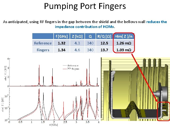
Pumping Port Fingers As anticipated, using RF fingers in the gap between the shield and the bellows wall reduces the impedance contribution of HOMs. f [GHz] Z [kΩ] Q R/Q [Ω] ≈Im( Z )/n Reference 1. 32 4. 3 340 12. 5 1. 26 mΩ Fingers 1. 34 4. 6 340 13. 7 1. 03 mΩ
Outline • Introduction • Vacuum Flange Shielding Studies – New Reference – Tube & Double Tube – Pumping Port Fingers – Gap Filling • Shield Comparison – R/Q Reduction • Next Steps
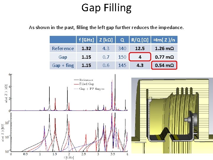
Gap Filling As shown in the past, filling the left gap further reduces the impedance. f [GHz] Z [kΩ] Q R/Q [Ω] ≈Im( Z )/n Reference 1. 32 4. 3 340 12. 5 1. 26 mΩ Gap 1. 15 0. 7 150 4 0. 77 mΩ Gap + fing 1. 15 0. 6 145 4. 3 0. 54 mΩ
Outline • Introduction • Vacuum Flange Shielding Studies – New Reference – Tube & Double Tube – Pumping Port Fingers – Gap Filling • Shield Comparison – R/Q Reduction • Next Steps
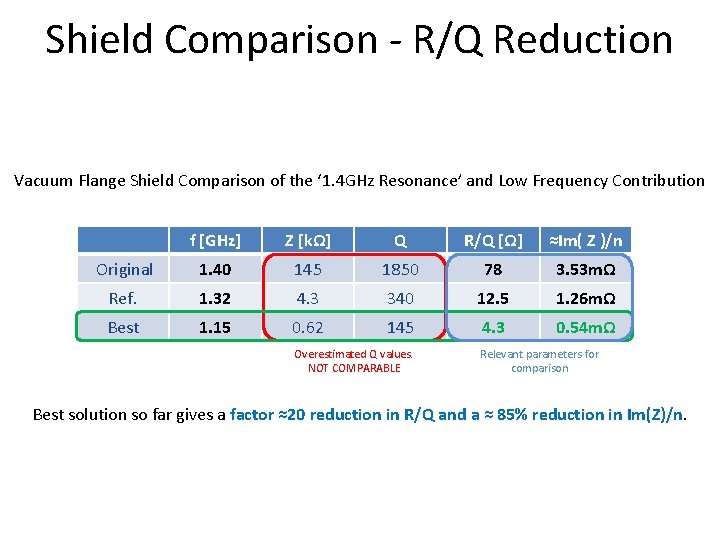
Shield Comparison - R/Q Reduction Vacuum Flange Shield Comparison of the ‘ 1. 4 GHz Resonance’ and Low Frequency Contribution f [GHz] Z [kΩ] Q R/Q [Ω] ≈Im( Z )/n Original 1. 40 145 1850 78 3. 53 mΩ Ref. 1. 32 4. 3 340 12. 5 1. 26 mΩ Best 1. 15 0. 62 145 4. 3 0. 54 mΩ Overestimated Q values. NOT COMPARABLE Relevant parameters for comparison Best solution so far gives a factor ≈20 reduction in R/Q and a ≈ 85% reduction in Im(Z)/n.
Outline • Introduction • Vacuum Flange Shielding Studies – New Reference – Tube & Double Tube – Pumping Port Fingers – Gap Filling • Shield Comparison – R/Q Reduction • Next Steps
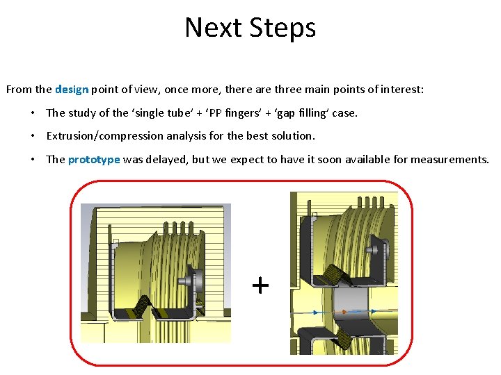
Next Steps From the design point of view, once more, there are three main points of interest: • The study of the ‘single tube’ + ‘PP fingers’ + ‘gap filling’ case. • Extrusion/compression analysis for the best solution. • The prototype was delayed, but we expect to have it soon available for measurements. +