Shielded Metal Arc Welding Safe practices when Arc


 n Electrode positive n Better penetrated welds")
 n Electrode Negative n Used when a high rate of filler")


- Slides: 27
Shielded Metal Arc Welding
Safe practices when Arc Welding Don’t stand in water n Discard frayed cords and wires n Keep flammable liquids away from heat n n Don’t look at the arc with out a number 10 lens.
Dress Code n n n Wear properly fitted clothes. When welding, sleeves should be buttoned and gloves should be worn. Wear boots or high top; Tightly laced shoes. Do not wear loose clothing, shirt tails, and unbuttoned sleeves around power equipment. Do not wear clothes that you do not want to get dirty.
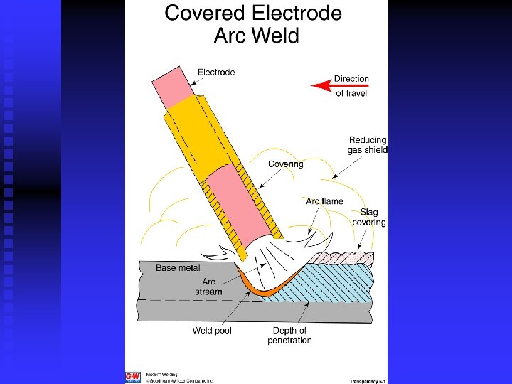
The Arc n When electrons jump through the air n When the pressure overcomes resistance n V=A X R
Parts of the Arc n n Arc stream u Vaporized metal t Appears yellow u Liquid metal t Appears green Arc flame u Natural gases surrounding arc stream t Pale red
Arc Control n Length n Angle
Reverse Polarity (DCEP) n Electrode positive n Better penetrated welds
Straight Polarity (DCEN) n Electrode Negative n Used when a high rate of filler metal is required. n EXX 2 X Electrodes
Alternating Current n Stops and starts u Must have enough voltage restart arc n Good penetration n Less expensive
Classification of Steel Electrodes Electrode designated by “E” followed by a 4 - or 5 - digit number n First two or three digits - minimum tensile strength as-welded deposited weld metal expressed in thousands of pounds per square inch (1000 psi) u E-60 xx - 60, 000 psi TS u E-120 xx - 120, 000 psi TS n
Classification of Steel Electrodes n Third or fourth digit refers to the welding position. u E-xx 1 x - all positions u E-xx 2 x - flat and horizontal fillet positions u E-xx 3 x - flat position only
Classification cont. n The fourth or fifth and last digit indicates the type of welding current and the type of flux covering u E-xx 10 - DC reverse polarity (electrode positive) only (cellulose sodium). u E-xx 11 - AC or DC reverse polarity (cellulose potassium ) Fast freeze, cutting u E-xx 13 - AC or DC straight polarity (titania potassium)
Factors of Electrode Selection Type of metal to be welded n Thickness of metal n Position of weld n Type of power (DC or AC) n Cleanliness of metal n Weld bead appearance desired n
Flux n n n n Improves the performance in handling, storage and operation of the electrode Floats out impurities Directs arc stream (stabilizer) Insulator Prevents oxidation (slag or gas) Holds in heat Iron-powder improves striking ability and increases metal deposition rate
Striking the Arc n Pecking u Touching electrode to the base metal and moving away to proper arc distance. Moving electrode in a vertical motion. u Can start precisely where the weld is to be. n Scratching u Moving electrode across base metal then moving electrode away to the proper arc distance. u Dose not work good in tight places
Common Striking Problems n Sticking u Lift electrode and metal u Break electrode from metal u Remove electrode from clamp n Arc is extinguished u The electrode is moved to far away from the base metal after the arc is struck.
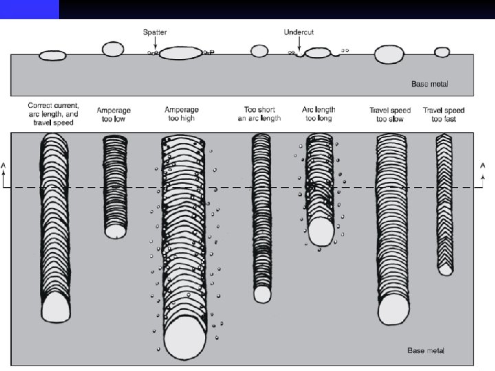
Arc Length n Longer arc u Increases Resistance u Increases Voltage u Decreases Current u Decreases filler consumption n Shorter arc u Decreases Resistance u Decreases Voltage u Increases Current u Increases filler consumption
Arc Length n Should be no more then ¼ inch n The sound of the arc should sound like eggs frying
Bead Width n Stringer bead u Only motion is in the direction of travel u About 3 times the width of the electrode u With 1/8 inch electrode should be 3/8 inch n Weaving bead u Motion side to side as well as forward u About 6 times the width of the electrode u With 1/8 inch electrode should be 3/4 inch
Stringer Bead
Weaving Bead
Electrode Angle n Should be 15° to 20° tipped forward in the direction of travel n Stringer bead should be at 90° from the base metal
Travel Speed n Bead width n Bullet-nose-shaped ripples
Restarting n Strike ark 3/8 inch in front of previous weld n Move back to crater n Move forward to finish weld
Restarting