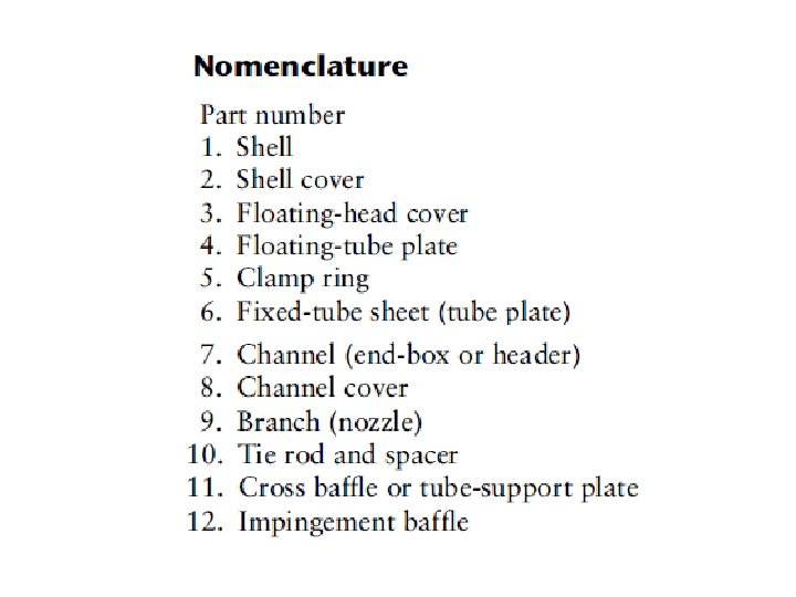
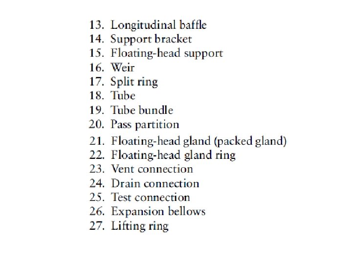
SHELL AND TUBE EXCHANGERS CONSTRUCTION DETAILS Advantages of

SHELL AND TUBE EXCHANGERS CONSTRUCTION DETAILS

Advantages of Shell and Tube HEX • The configuration gives a large surface area in a small volume; • Good mechanical layout: a good shape for pressure operation; • Uses well-established fabrication techniques; • Can be constructed from a wide range of materials; • Easily cleaned; • Well-established design procedures.

Basic design

Fixed-tube plate The simplest and cheapest. The tubes cannot be removed for cleaning. There is no provision for expansion

U-tube Widely used only for clean fluids. Difficult to change tubes.

Internal floating head without clamp ring Can be used for wide range of temperature differentials. Can be used for fouling fluids. Can be easily cleaned.

Internal floating head with clamp ring

External floating head

Kettle reboiler with U-tube bundle
![Tubes -dimensions • Diameters are in the range [16 -50] mm. • [16 -25]](http://slidetodoc.com/presentation_image_h2/3a5ca3fcc582a4c5a0a1c3f4f60cb9c8/image-12.jpg "Tubes -dimensions • Diameters are in the range [16 -50] mm. • [16 -25]")
Tubes -dimensions • Diameters are in the range [16 -50] mm. • [16 -25] mm are preferred for most duties. • Larger tubes are used for fouling fluids because they are easier to clean mechanically. • Tube thickness (gauge) is selected to withstand pressure and corrosion. • Preferred tube lengths are 6, 8, 12, 16, 20 and 24 ft. • The optimum tube length to shell diameter is between 5 and 10.

Standard dimensions for steel tubes

Tubes -arrangement • Tubes are arranged in equilateral triangle, square, or rotated square pattern.

• Triangular and rotated square patterns give higher heat transfer rates but higher pressure drop. • Square or rotated square used for heavily fouling fluids. • Tube pitch: the distance between tube centers. • Tube pitch is recommended to be 1. 25 times the tube outside diameter.

Tube passes • Tube passes are designed to increase the length of flow path. • The number of passes is selected to give the required tube-side design velocity. • Tube passes can go up to 16 passes.

Shells • For diameters up to 24 in, shells are normally constructed from standard, close tolerance pipe. • Above 24 in, they are rolled from plate.

Minimum shell thickness standards
 • The bundle diameter depends on the number of")
Tube sheet layout (Tube count) • The bundle diameter depends on the number of tubes and the number of passes. • The bundle diameter can be estimated from:

Constants for triangular and square patterns
 • One pass shell (E shell)")
Shell types (passes) • One pass shell (E shell)
 Used to reduce the pressure drop")
Split flow (G shell) Used to reduce the pressure drop
 Used to reduce the pressure drop")
Divided flow (J shell) Used to reduce the pressure drop
 Used when the temperature difference is not")
Two-shell pass with longitudinal baffle (F shell) Used when the temperature difference is not suitable for a single shell pass
")
Double split flow (H shell)

A common method to describe the exchanger is to designate the number of shell and tube passes : m/n; where m is the number of shell passes and n is the number of tube passes.

Baffles • Used in the shell to direct the fluid stream across the tubes to increase the fluid velocity and so improve the rate of heat transfer.

Segmental baffles • The most commonly used baffles

Segmental and strip

Disc and doughnut

Orifice

Baffles for condensers

Baffle cuts • The baffle cut is a term used to specify the dimensions of a segmental baffle. • It is the height of the segment removed to form a baffle expressed as a percentage of the baffle disc diameter. • Baffle cuts from 15 to 45% are used. • The optimum is generally between 20 and 25%

Baffle thickness and spacing • The minimum thickness for baffles are given in standards • The baffle spacing used range from 0. 2 to 1. 0 shell diameter. • A close baffle spacing will give higher heat transfer coefficient but higher pressure drop. • The optimum spacing will be 0. 3 to 0. 5 times the shell diameter.
 -Corrosion: the more corrosive in")
General Design Considerations • Fluid allocation (no phase change) -Corrosion: the more corrosive in the tube (to reduce the cost). -Fouling: the fluid with greatest tendency to foul in the tube (easier to control and clean). -Temperature: the hottest in the tube (to reduce the cost and the heat loss). -Operating pressure: High pressure in the tube (cheaper) -Pressure drop: fluid with the lowest pressure drop in the tube (higher HTC). -Viscosity: for turbulent flow, the more viscous fluid in the shell (Higher HTC) -Stream flow rates: lowest flow rate in the shell (economical design)

Pressure Drop • Pressure drop available to make the fluid flow through the exchanger vary from mbar to several bars. • Economic analysis is used to determine the lowest operating cost. • Liquid: • Vapor:

Fluid physical properties • The fluid physical properties required for heat exchanger design are density, viscosity, thermal conductivity, and temperature-enthalpy correlations (specific and latent heats).

TUBE-SIDE HEAT TRANSFER COEFFICIENT • Turbulent Flow:

• Laminar flow: • If Nu is less than 3. 5, it should be taken as 3. 5

Heat Transfer Factor, jh • It is often convenient to correlate heat transfer data in terms of a heat transfer j factor. • The use of the jh factor enables data for laminar and turbulent flow to be represented on the same graph

Tube-side heat transfer factor

Viscosity Correction Factor • The viscosity correction factor will normally be significant only for viscous liquids.

Tube-Side Pressure Drop • There are two major sources of pressure loss on the tube side of a shell and tube exchanger: 1. The friction loss in the tubes. 2. The sudden contraction/expansion and flow reversals.

• The tube side pressure drop can be calculated from:

Tube side friction factor

SHELL-SIDE HEAT TRANSFER AND PRESSURE DROP • The flow pattern is complex

Procedure for calculating pressure drop and HTC in the shell side of a single shell pass HEX 1. Calculate the area for cross-flow As for the hypothetical row of tubes at the shell equator, given by:

2. Calculate the shell-side mass flux Gs and the linear velocity us:
. For a square pitch arrangement: -")
3. Calculate the shell-side equivalent diameter (hydraulic diameter). For a square pitch arrangement: - For an equilateral triangular pitch arrangement:

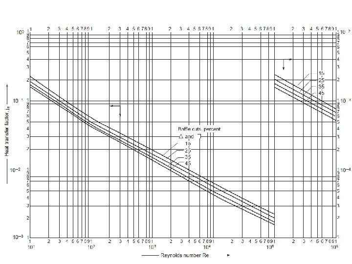
4. Calculate the shell-side Reynolds number, given by: 5. For the calculated Reynolds number, read the value of jh from Figure 12. 29 for the selected baffle cut and tube arrangement, and calculate the shell-side heat transfer coefficient hs from:

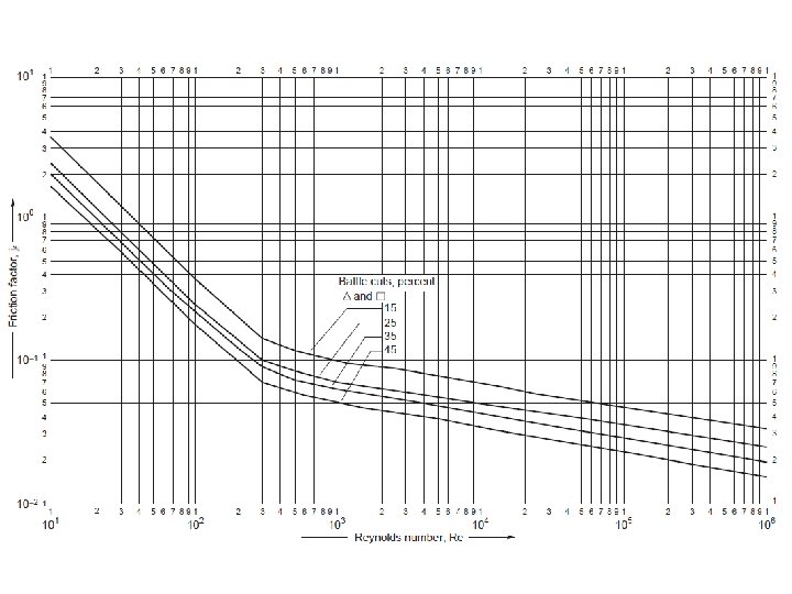
6. For the calculated shell-side Reynolds number, read the friction factor from Figure 12. 30 and calculate the shell-side pressure drop from:
- Slides: 53