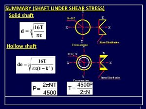
Shear Stress Torsional Deflection Y RD2 X X


- Slides: 12

Shear Stress Torsional Deflection Y R=D/2 X X Y D L X Y Cross-section Stress Distribution Y X T


Example No. 2 A pulley of diameter 750 mm and a gear of 280 mm diameter are mounted on a steel shaft. The belt pulls on the pulley with 1670 N and 1330 N at 450. The gear tooth force is 900 N. The allowable shear stress and tensile stress for the shaft material are 57 N/mm 2 and 71 N/mm 2 respectively. Determine the shaft diameter. 1670 N 450 A B 1330 N 375 900 N 500

Reactions -Pulling forces of the belt should be resolved in the vertical and horizontal directions. i. e. , Fv : Vertical tension component. Fh : Horizontal tension component. Fv = Fh = (1670+1330)sin 450 = 3000 sin 45 =2120 N

Vertical Reactions 2120 N From Equilibrium: 900 N A B S M @ B : 375 RA (375+500) = 375 500 (900 500)+2120 (375+500) 1250 RA = 450000+ 1855000 = 2305000 M @ A : RA RA = 1844 N RB (375+500) = 900 (375+375)+2120 375 1250 RB = 675000 + 795000 CKECK : RB = 1176 N FY = 0 : RA + RB = 1844+1176 = 2120 + 900 = 3020 Vertical reactions are right. RB

Horizontal Reactions From Equilibrium: S M @ B : 2120 N A B 375 HA (375+500) = 2120 (375+500) 375 500 1250 HA = 1855000 HA = 1484 N HA M @ A : HB (375+500) = 2120 375 1250 HB = 795000 HB = 636 N CKECK : FY = 0 : HA + HB = 1484 + 636 = 2120 Horizontal reactions are right. HB

Vertical Load Diagrams Horizontal 2120 N 900 N C A 375 D 375 1844 N + 276 2120 N B 500 S. F. D. 1176 + 1484 + 556. 5 588 N. m MT. D. 500 636 N 636 B. M. D. 127. 5 N. m 375 1484 N 1844 N _ B 375 1176 N + 619 A T =127. 5 N. m

Critical Section at “C” is the critical one This section loaded by: 1. Shear force Qx =1484 N & Qy =1844 N (Neglected values) 2. Bending Moment Mx =556. 5 N. m & My =619 N. m 3. Torque Mt = 127. 5 N. m

Shaft Design 1. Design Based on Bending Moment Mx =556. 5 N. m But, My =619 N. m all = 71 N/mm 2 (given)

Shaft Design 2. Design Based on twisting Moment Mt =127. 5 N. m And, all = 57 N/mm 2 (given)

Shaft Design 3. Design Based on twisting & bending Moments Mt =127. 5 N. m Mx =556. 5 N. m My =619 N. m Design will be carried out according to one of theories of elastic failure. (i. e. , Maximum shear or maximum principle stress theory).

EN D
 Torsion equation
 Torsion formula for shaft
 Torsional shear stress formula
 Ssy in machine design
 Specific weight unit
 Critical resolved shear stress
 Mohr's circle stress transformation
 Positive shear stress convention
 Shear stress in laminar flow
 Rectangular cross section
 Tc/j shear stress
 Torsional load
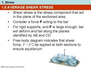
 Average shear stress formula
