Shaping operations are generally divided into three groups


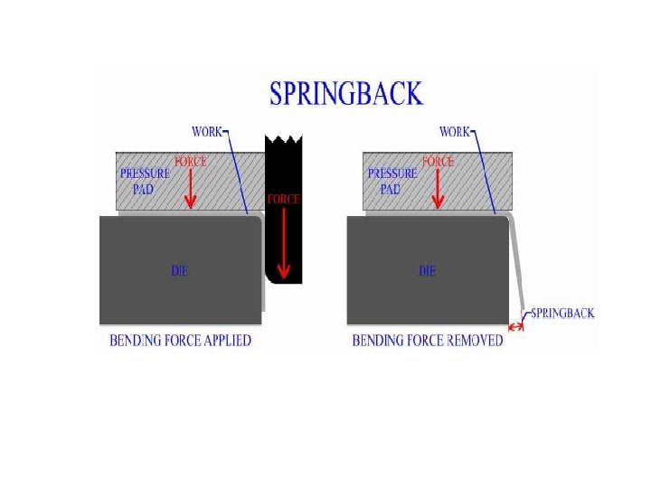


 Fig: 10 -6(b) Fig: 10 -6(c)")
, its fibres experience a distortion")


 * 2π (IR + kt) Where,")

 * 2π (IR + k *t)")
 / W Where, F =")


 Possible number of reduction for a given ratio of")

 Use 1 st equation when d/r is 20")


- Slides: 31
Shaping operations are generally divided into three groups based upon how the parent metal flows or deforms during the shaping process , namely q. Bending q. Forming q. Drawing
Bending : Bending is defined as shaping metal around a straight axis which extends completely across the material. ØThe result is a plane surface at an angle to the original plane of the work piece material. ØMetal flow is uniform along the bend axis , with inner surface of the bend in compression and the outer surface in tension.
Forming: Forming is defined as shaping metal around a curved axis instead of a straight one. ØA part that is formed generally takes the shape of the punch or die. ØMetal flow is not uniform.
Drawing: Drawing is the name given to the production of cups , shells , boxes and similar articles from metal blank. ØDrawing is the most complicated of the three sheet metal shaping process. ØA drawing operations begins with a flat blank which is transformed into a cup or shell. ØThe parent metal is subjected to severe plastic deformation.
Bending Methods V Bending Wiping Bending Air Bending Dies Bottoming Dies In Case Of, Air Bending Dies : Figure Please See Class Note (Punch does not bottom out). Bottoming Dies : Figure Please See Class Note ( Punch bottoms out ).
Air Bending : When the punch does not bottom out then it is called air bending. Advantages Of Air Bending Dies : ü One set of die & punch can be used to bend w/p with different thickness to various angles ü Least pressure Is needed Limitations Of Air Bending Dies : ü Less Accuracy ü Spring back is more. (tendency of material to be straight for elastic property )
Bottoming Dies : The punch is allowed to bottom out at the V bend dies . The material is squeezed between the punch & die at the end of the punch stroke. Advantages of Bottoming Dies: ü Higher degree of accuracy ü Sharper inside corners ü Less spring back Limitations of Bottoming Dies: ü Only one type of bending can be done by one set of die and punch ü 3 -10 times more pressure than air bending
Wiping Dies: The work piece is clamped to a die block by a spring loaded or fluid cylinder pressure pad and the punch wipes the extended material over one edge of the die.
Spring Back: When the force used to create the bend is removed, the recovery of the elastic region results in the occurrence of spring back. Spring back is the partial recovery of the work from the bend to its geometry before the bending force was applied. The magnitude of spring back depends largely on the modulus of elasticity and the yield strength of the material. Typically the results of spring back will only act to increase the bend angle by a few degrees, however, all sheet metal bending processes must consider the factor of spring back.
Methods of Preventing Spring Back: v Over bending : It is used for V Die air Bending. Some more bending is made than required , then due to spring back it results in desired bending. v Corner Setting : Spring back is prevented by coining (squeezing) the metal slightly at the corner in order to relieve elastic stresses.
Methods Of Corner Setting : Ø Making the edge of the punch slightly flat. Ø Making the edge of the punch slightly rough. v Ironing:
Methods Of Ironing: Fig: 10 -6 (a) Fig: 10 -6(b) Fig: 10 -6(c)
Bend Allowance: As a sheet metal is bent (Fig), its fibres experience a distortion such that those nearer its outside, convex surface are forced to stretch and come in tension, while the inner fibres come in compression. Somewhere, in the cross section, there is a plane which separates the tension and compression zones. This plane is parallel to the surface around which the sheet is bending, and is called neutral axis. The position of neutral axis depends on the radius and angle of bend. BEND ALLOWANCE It is the length of the neutral axis in the bend, (Fig. ) This determines the blank length needed for a bent part.
Fig: BEND ALLOWANCE
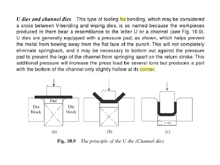
Spring back prevention in U dies:
Determination of Bend Allowance : B = (A/360) * 2π (IR + kt) Where, B = Bending allowance (arc length of neutral axis in inch ) A = Bend angle ( in degree ) IR = Inside radius of bend ( in inch ) t = Metal thickness ( in inch ) k = constant for neutral axis location Use , k = 0. 33 for IR < 2 t k = 0. 50 for IR > 2 t
Determine the blank length of the following product : For Figure Please See Class Note Blank Length , L = L₁ + L₂ + L₃ + L₄ + L₅ L = 2 L₁ + 2 L₂ + L₃ ; [ L₁ = L₅ , L₂ = L₄ ] L₁ = L₅ = 2 – (IR + t) = 2 – (3/ 6 + 1/8 ) = 1. 6875 inch L ₃ = 4 – 2(IR + t) = 4 – [ 2 (3/16 + 1/8) ] = 3. 375 inch
L₂ = L₄ = Bend Allowance = (A/360) * 2π (IR + k *t) = (90/360) * 2 * 3. 1416 ( 3/16 + 0. 33 * 1/8 ) = 0. 3593 Here , IR = 3/16 , 2 t = 2 * 1/8 = 4/16 So, IR <2 t ; k = 0. 33 L = 2 L₁ + 2 L₂ + L₃ = 2 * 1. 6875 + 2 * 0. 3593 + 3. 375 = 7. 4686 “
Bending Pressure /Force: F = ( k. Lst² ) / W Where, F = Bending force required ( in tons ) L = Length of the bend part ( in inch ) s = Ultimate tensile strength (in ton / in² ) t = Metal thickness k = Die opening Factor w =Width between contact points on die Cont, d
ØFor Air bending k = 1. 33 ; when Die opening = 8*Material thickness k = 1. 20 ; when Die opening =16*Material thickness ØFor U bending and channel bending k = 0. 67 ; ØFor Wiping bending k = 0. 333 W is determined as shown in fig: ØFor both U bending & wiping , W = R₁ + R₂ + C , C = t
Problem : Determine the bending force in tons for a 45 degree bend in 24 ST 3 aluminium [with s = 65000 psi] ; 0. 0621 in thickness ; 4 ft long. The bend is air bending. The die opening is 8 times the material thickness. Solution : Here , k = 1. 33 ; ( as the die opening is 8 times the material thickness) L = 4 ft = 48 inch t = 0. 0621 inch s = 65000 psi W = 8 * 0. 0621 inch
Problem : Calculate the bending force in tons for the channel bend. The bend length is 36 inch and die radius is 0. 375 inch[ s = 61000 psi ](Fig please see class note) Solution : Here , k = 0. 67; ( For U bending ) L = 36 inch t = c = 1/8 s = 61000 psi W = R₁ + R₂ + C =. 375 + 3/16 + 1/8 = 0. 6875
Forming dies – types : ü Solid form dies üPad type form dies üCurling dies üEmbossing dies üCoining dies üBulging dies üAssembly die
Drawing Dies : Types of Drawing Dies : Ø Shallow Drawing when h/d ≤ 0. 5 Ø Deep Drawing when h/d > 0. 5 Where , h = outside height d = outside diameter Percent Reduction and depth of draw : Percent reduction , P = 100 ( 1 – d/D ) where P= Percentage reduction, d=ID of drawn shell, D= OD of blank Maximum allowable reduction in one stroke / one draw , Theoritical ≈ 50 % Practical ≈ 40 % Example: The drawing of a 3 inch dia cup from a 5 in dia blank results in a 40% reduction. Percent reduction , P = 100 ( 1 – d/D ) = 100 ( 1 – 3/5 ) = 40 %
Table 10. 4 : (Donaldson) Possible number of reduction for a given ratio of shell height to diameter : Ratio h/d Numbers of reduction Reduction 1 st Draw 2 nd Draw 3 rd Draw Upto 0. 75 1 40 0. 75 – 1. 5 2 40 25 1. 5 – 3. 0 3 40 25 15 3. 0 – 4. 5 4 40 25 15 4 th Draw 10
Blank size determination : The following equations can be used to calculate the blank size for cylindrical shells of relatively thin metal. D = Blank Diameter , d = Cup/Shell diameter (outside) h = Cup/Shell height (outside) , r = Corner radius of punch Blank size determination : (contd. ) √(d² + 4 dh) If d/r ≥ 20 √((d² + 4 dh) – 0. 5 r) If d/r = 15~20 √((d² + 4 dh) – r) If d/r =10~15 √[(d– 2 r)²+4 d(h-r)+2πr(d-0. 7 r)] If d/r < 10 D =
Blank size determination : (contd. ) Use 1 st equation when d/r is 20 or more Use 2 nd equation when d/r is between 15 - 20 Use 3 rd equation when d/r is between 10 - 15 Use 4 th equation when d/r is less than 10 Trim allowance: The extra material added to the blank diameter is referred to as trim allowance Final/ Actual Blank Size = D + Trim Allowance General Rule for trim allowance : Add 1/8 inch for cup dia upto 1 inch , then add 1/8 inch per extra 1 inch dia. Example: 0. 5 inch should be added to the blank diameter for a cup diameter of 4 inch.
Drawing Force : The amount of force required to shape a symmetrical cup by drawing can be calculated from the following formula from the ASTME “Die design handbook”. P = πdts ( D/d – c ) Where , P = Drawing force/pressure. d = Cup/shell outside diameter. t = Metal thickness. s = Yield strength of the material. D = Blank diameter. C = Constant to cover friction and bending( 0. 6 to 0. 7 for ductile materials)