Shape from Shading 1 Topics Reflectance map and


 For")


 u u for each(p, q), N=(p, q, 1) light")
 u Lambertian q p Self-shadow line")
have the surface reflection as")


 masking 2) shadowing g(i, e)")

 light is wave")
 Torrance and Sparrow + Beckmann and Spizzichino •")
 contours")
 from image irradiance (brightness) 0. 8 (p, q, 1)")


 Photometric stereo gives a")

 should be same as those of the")
 needle map iterative method brightness depth map")

")

 and q(x, y) 2. derivative of the")


 space on the (f, g)")


 g = G / (R+G+B) b =")

 – a linear transform")


- Slides: 75
Shape from Shading #1
Topics Reflectance map and Photometric stereo u irradiance and radiance u basic concepts of reflection u reflection map u photometric stereo
Brightness irradiance amount of light falling on a surface falling energy measured by a unit surface area [watt/m 2] radiance amount of light radiated from a surface emitting energy measured from a unit forshorted light source surface area to a unit solid angle [watt/ m 2 ・Sr] solid angle --- steradian A R Θ
Reflection geometry • irradiance at a pixel depends on • illumination • materials • geometry • under the same illuminate condition, we observe irradiance difference on the same material surface there is a relationship between pixel irradiance and geometry • Reflectance geometry N L i e g i=incidence angle e=emitting angle g=phase angle V L=illumination N=normal V=viewer
Gradient space reflection functions are defined in the local coordinate system(e, i, g) For our development, we will redefine the reflectance geometry in viewers is always on the Z axis the gradient space q p
Surface and body reflection u Surface reflection and body reflection surface body reflection incident light air internal pigment body surface reflection=gloss, highlights very directional(specular) body reflection =object color all direction(diffuse) plastic, paint have both metal has only surface reflection
Model for body reflection Diffuse---scatters in all directions common approximation: equal in all directions “lambertian”Lambertian’s cosine law “perfectly diffuse reflector” reflectance=constant * geometric factor f(i, e, g) = Kb * cos i why cos i ? angle of incidence affects “density” of illumination. (irradiance) irradiance=light/area light=1 area=1/cos i irradiance = cos i
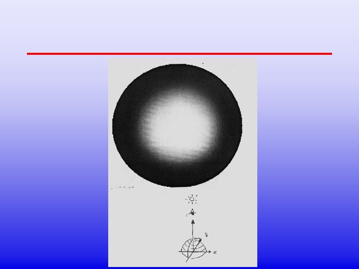
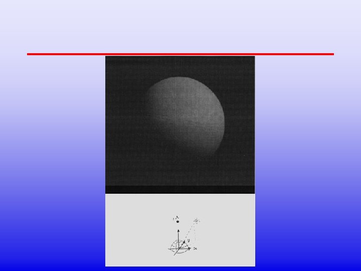
Calculating a reflection map (Lambertian) u u for each(p, q), N=(p, q, 1) light source direction, S= q iso-brightness contour 0. 5 0. 8 0. 9 p
Reflectance map(continue) u Lambertian q p Self-shadow line
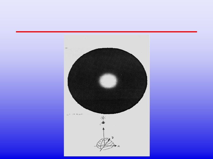
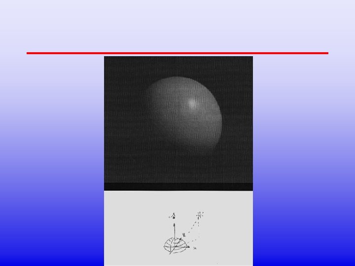
Surface reflection metals have the only surface reflection dielectrics(plastics, paint)have the surface reflection as well as the body reflection simplest approximation: perfect mirror i S N i S’ reflection is specular direction, S’ S’ is coplanar with S, N SN = i = NS’: opposite sides
Real surfaces are rough : light scatters tells amount of light at each angle Phong’s model calculate angle between S’ and V ---α n f-surface(i, e, g)=Ks * cos α typical : n = 10 to 500 heuristic model 3 5 n=1 n Cos α
Reflectance map q bright dark p q p
Better model of surface reflection u Phong’s model R=Ks cosnα not based on physics just looks OK for graphics, not really accurate off-specular effect Phong’s model composite surface reflection Phong’s model real surface Torrance and Sparrow --- geometrical optics Beckmann and Spizzichino --- physical optics
Torrance and Sparrow model u Geometrical optics – a collection of planar mirror-like facets – surface reflection caused only by these microfacets – their sizes are much larger than wave length average normal direction α microfacet slopes to be normally distributed V-shaped valleys facet normal
Surface reflectance u surface reflectance = constant for material * effect of one ray * % not blocked by others (geometrical attenuation) * % of all facets involved
Effect of one ray i incoming energy = A cos i e outgoing energy =(A cos i) / (A cos e) =cos i / cos e
Geometric attenuation 1) masking 2) shadowing g(i, e)
% of all facets involved N reflection distribution facet normal distribution α i α
Beckmann and Spizzichino model physical optics surface is continuous h(x, y) light is wave reflection off of surface roughness is amplitude and spatial frequency of variations in h(x, y) E(x, y, z) “field” of light energy surface is assumed to be a perfect conductor(metal) --- > Maxwell’s equation exact solution is vicious integral where
Our model (Nayer, Ikeuchi, Kanade 89) Torrance and Sparrow + Beckmann and Spizzichino • diffuse lobe --- cosine function • specular spike --- delta function • specular lobe --- gaussian function
Calculating reflectance map specular lobe + diffuse lobe recall q Lambertian (diffuse lobe) contours p Specular peak
Shape-from-shading recover object shape (orientation) from image irradiance (brightness) 0. 8 (p, q, 1) brightness surface orientation E(x, y)=R(p, q) -- image irradiance equation 0. 8 q p gives one constraint on the gradient space at each pixel --- > ill-posed problem (cannot solve !!!!!)
Photomotric stereo • one image irradiant equation gives only one constraint --- > use multiple equations at each pixel. • take multiple images from the same points under different light source directions q q p p • recall different light source directions give different reflectance map • at each pixel, multiple irradiance values
Photometric Stereo
Analytical solution • real world gives complicated light source direction --- > look-up table method
Look-up table method
Summary Basic concepts of reflection radiance and irradiance reflection geometry surface reflection and body reflection Shape-from-shading problem reflectance map image irradiance equation photometric stereo
Shape-from-shading #2
Shape-from-shading #2 get a depth map from a needle map get a needle map from a single image
Depth from surface orientation 1 dimensional case recall 1 2 dimensional case
Recovering depth map from a needle map (direct integration method) Photometric stereo gives a needle map assume a depth at the origin get depth along the x of the needle map get the depth map
Direct integration rapid accumulates errors
Relaxation method u observed orientation (p, q) should be same as those of the depth map (zx, zy) u reduce the total error within a boundary (the calculus of variations See Horn pp. 469 -474) u an iterative formula
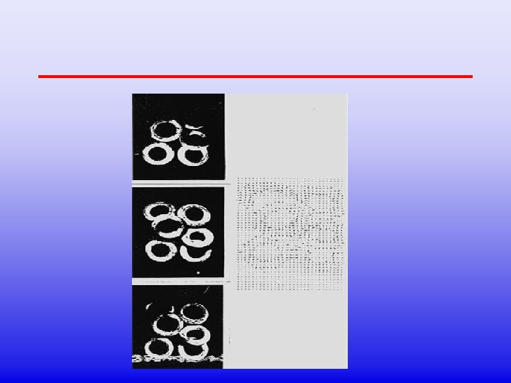
Relaxation method (Example) needle map iterative method brightness depth map
Shape-from-shading with a single view Photometric stereo uses multiple images. Is there a way to recover shape from a single image? Yes, there is a way. 1. characteristics strip expansion method: obtain surface orientation along characteristics strips of image irradiance equation (Horn 75) 2. relaxation method: obtain surface orientation using image irradiance equation and smoothness constraint (Ikeuchi and Horn 81) 3. global method: assume a surface is a part of sphere (Pentland 83)
Characteristic strip expansion method the steep descent direction of the reflectance map (gradient space) the steep descent direction of the image brightness (image brightness)
Characteristic Strip move towards the SDD of the reflectance map on the image plane move towards the SDD of the image brightness on the gradient space SDD of RM SDD of IB
Proof 1. Taylor expansion of p(x, y) and q(x, y) 2. derivative of the image irradiance equation
Move towards the SDD of the reflectance map on the image plane on the image then, what happen to (p(x, y), q(x, y)) ? move towards the SDD of the image brightness on the gradient space on
y q x 0. 5 0. 1 0. 4 0. 2 0. 3 0. 4 from a known point, (you know (p, q) and E) you can determine (p, q) along a characteristic strip 0. 3 0. 2 0. 1 p
Horn 75 y x q character strip p reconstructed contour
Problem of characteristic stip method 1. Error accumulation. ? ? ? 2. The method starts from a singular point the start point is unreliable. 3. Determine surface orientation only along characteristic stripes. 4. Occluding contours are big evidences. We cannot use that information. (p, q) become infinite. relaxation method with occluding contours
Occluding boundary Surface orientations on occluding boundaries are known These surface orientations cannot be represented by the g We will use the stereographic plane, (f, g). On (f, g) plane boundary condition
Stereographic Projection occluding boundaries lie on the unit circle p gradient space gaussian sphere q
Relaxation method 1. Image irradiance equation on (f, g) space on the (f, g) space, we can also define a reflectance map. 2. Smoothness constraint. Neighboring points have roughly the same surface orientation.
Relaxation method 3. Set up a minimization problem. →min 4. Using the calculus of variations get iterative formula.
Ikeuchi & Horn 81 brightness image needle map occluding boundary n+h solution n+1+h solution depth map
Summary 1. Gaussian sphere and reflectance map 2. Get a depth map from a needle map 1. direct integration 2. relaxation method 3. Get a needle map from a single image 1. characteristic strip expansion method 2. relaxation method regularization 4. Read Horn pp. 244 -269, B&B pp. 93 -101
Color Theory for Computer Vision
Color Theory for Computer Vision Color in several domains: – Physics – Human vision – Psychophysics – Perception – Computer Vision Color problems in Computer Vision: – Color for segmentation – Color for reflection physics
Physics of Color Spectrum of electromagnetic radiation wavelength = ultraviolet gamma x-rays 10 -9 10 -11 500 nm 380 nm violet visible infrared blue 10 -7 10 -6 micro 100 10 -3 600 nm green yellow orange radio 700 nm 760 nm red characterized by spectral power distribution (SPD) S( ), E( ) monochromatic mixture (typical)
Physiology of human color vision retina The retina has four types of receptor cells. • “red” cones • “green” cones • “blue” cones • rods (darkness) 380 nm red cone response 760 nm = green cone response = blue cone response color vision =
Color space If we approximate spectral power distribution by vector, it’s a matrix multiplication. red = green = blue = red green blue green = spectral space : infinitely many dimensions color space : 3 dimensions each point is a “color” blue red many SPDs have same “color”
Alternate color space other isomorphic color spaces formed by linear transforms green C B blue red green blue = define new axes A A B C = red green blue linear transform gives new axes = new response function =
Psychophysical color X-Y-Z: international standard color space agreed upon by Commision Internationale de I’Eclairage (CIE) – particular linear transform of human cone responses – Two spectral distributions that result in the same values in the space appear indistinguishable – all colors have positive x, y, z Each point in X-Y-Z is a different color Chromaticity x = X / (X+Y+Z) ≒ R / (R+G+B) y = Y / (X+Y+Z) ≒ G / (R+G+B) z = Z / (X+Y+Z) ≒ B / (R+G+B) since x+y+z = 1, z = 1 -(x+y). --- redundant usually plotted o x-y diagram Each point is many XYZ colors
Chromaticity diagram r = R / (R+G+B) g = G / (R+G+B) b = B / (R+G+B)
filter Color TV camera CCD sensor electrons lens CCD filter CCD
Color TV RGB defined by National Television Systems Committee (NTSC) – a linear transform of X-Y-Z – each value limited 0⇔ 255 – commercial TV needs an intensity white-black component for black-and-white TV – also needs to span the color space cyan u YIQ Y → main axis: white-black I → red-cyan Q → magenta-green Y white green blue black magenta red I Q
Color perception How do people describe color ? NOT “X-Y-Z” nor “R-G-B” ! People use cylindrical coordinates. hue, saturation, brightness B H S One plane of constant brightness blue green white violet S yellow H red hue+saturation form polar coordinates relationship to red-green-blue
Hue-Saturation-Brightness Space blue hue black white
Role of Color in Robot Vision 1. Feature space for 2 D segmentation more features → better discrimination 2. Color physics of reflection What physical information can color provide?
Color reflection physics surface reflection and body reflection incident light surface body reflection internal pigment air body u surface u body reflection has SPD of incident light reflection has SPD of body color
Separating reflection components by color Pixel color vectors are surface reflection body reflection Make a histogram fit parallelogram Project each pixel onto vectors Determine everywhere Klinker 88
Color space analysis body color vector in RGB space surface color vector in RGB space Color vector at a pixel is a linear combination of surface + body reflection color vector
Dichromatic Reflection Model u surface reflection has SPD of incident light u body reflection has SPD of body color surface reflection SPD of incident light body reflection SPD of body color
Color Space Klinker/Shafer/Kanade 88 u Linear combination a. S + b. B Surface comp: S green blue red Body comp: B
Separation Results
Summary Color in several domains: physics human vision perception TV camera Color problems in computer vision color for segmentation color reflection physics
Reference u u u Horn, B. K. P “Obtaining shape from shading information, ” in The Psychology of Computer Vision, P. H. Winston (ed. ), Mc. Graw-Hill, 1995 Ikeuchi, K. & B. K. P. Horn, “Numerical shape from shading and occluding boundaries, ” Artificial Intelligence, Vol. 17, 1981. Pentland, A. P. , “Local shading analysis, ” IEEE Trans. PAMI, Vol. 6, 1984. Klinker, G. J. , S. A. Shafer & T. Kanade, “The measurement of highlight in color image, ” Int. J. Computer Vision, Vol. 2, 1988. Nayar S. K. , K. Ikeuchi, and T. Kanade "Surface reflection: physical and geometrical perspectives", IEEE Trans. PAMI, Vol. 13, pp. 661634, 1991.