
SEU Tolerance in the ELMB Henk Boterenbrood software
SEU Tolerance in the ELMB Henk Boterenbrood software engineer R 2 E Workshop, June 2 -3 2009
Outline v What is the ELMB ? (plus brief history) v Some applications using the ELMB v Radiation tests on the ELMB v SEUs in the ELMB v SEUs and the ELMB software v Conclusion R 2 E Workshop, June 2 -3 2009 H. Boterenbrood 2
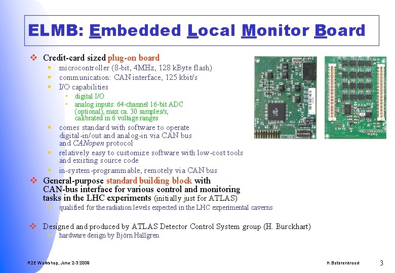
ELMB: Embedded Local Monitor Board v Credit-card sized plug-on board § microcontroller (8 -bit, 4 MHz, 128 k. Byte flash) § communication: CAN interface, 125 kbit/s § I/O capabilities • digital I/O • analog inputs: 64 -channel 16 -bit ADC (optional), max ca. 30 samples/s, calibrated in 6 voltage ranges § comes standard with software to operate digital-in/out and analog-in via CAN bus and CANopen protocol § relatively easy to customize software with low-cost tools and existing source code § in-system-programmable, remotely via CAN bus v General-purpose standard building block with CAN-bus interface for various control and monitoring tasks in the LHC experiments (initially just for ATLAS) § qualified for the radiation levels expected in the LHC experimental caverns v Designed and produced by ATLAS Detector Control System group (H. Burckhart) § hardware design by Björn Hallgren R 2 E Workshop, June 2 -3 2009 H. Boterenbrood 3
Why develop the ELMB ? v Common solution for relatively simple control/monitoring tasks § Reduce design effort (hardware, software) by individual institutes/subdetectors § Simplify spares and maintenance issues (15 years) § Interfacing custom designs in a ‘standard’ way to the (ATLAS) Detector Control System (DCS) • hardware and software (CANopen protocol on the CAN-bus) v No commercial solution to meet all requirements: § low power § low cost § high I/O density (possibility to connect many channels to one module, in particular analog-in) § In-System-Programmable (i. e. remotely in-situ, via CAN-bus) § for use in the LHC experiments • not sensitive to magnetic field • radiation tolerance, qualified to a certain level • be able to change component if not sufficiently rad-tolerant (rad-hard components out of the question because of cost) R 2 E Workshop, June 2 -3 2009 H. Boterenbrood 4
ELMB: brief history v After a few prototypes… § LMB (with 2 micros with small memory) ca. 40 produced CERN + § ELMB 103 (with ATmega 103 microcontroller + other) ca. 300 produced, in 2001 NIKHEF CERN v Final design: ELMB 128 (with ATmega 128 microcontroller: Bootloader section) § ELMB 128 A: with analog part § ELMB 128 D: without analog part v Pre-series of 650 ELMB produced, end of 2002 § to satify initial (ATLAS) subdetector needs v Production of >10000 units, in 2004 § ATLAS, >5000 § LHC Rack & Gas Systems, ca. 2000 § Other LHC experiments, ca. 1400? R 2 E Workshop, June 2 -3 2009 H. Boterenbrood 5
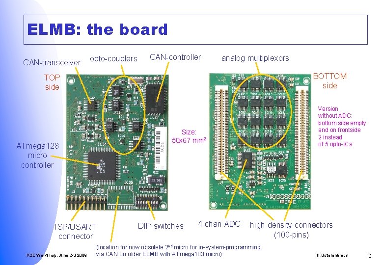
ELMB: the board CAN-transceiver opto-couplers CAN-controller analog multiplexors BOTTOM side TOP side Size: 50 x 67 mm 2 ATmega 128 micro controller ISP/USART connector R 2 E Workshop, June 2 -3 2009 Version without ADC: bottom side empty and on frontside 2 instead of 5 opto-ICs DIP-switches 4 -chan ADC high-density connectors (100 -pins) (location for now obsolete 2 nd micro for in-system-programming via CAN on older ELMB with ATmega 103 micro) H. Boterenbrood 6
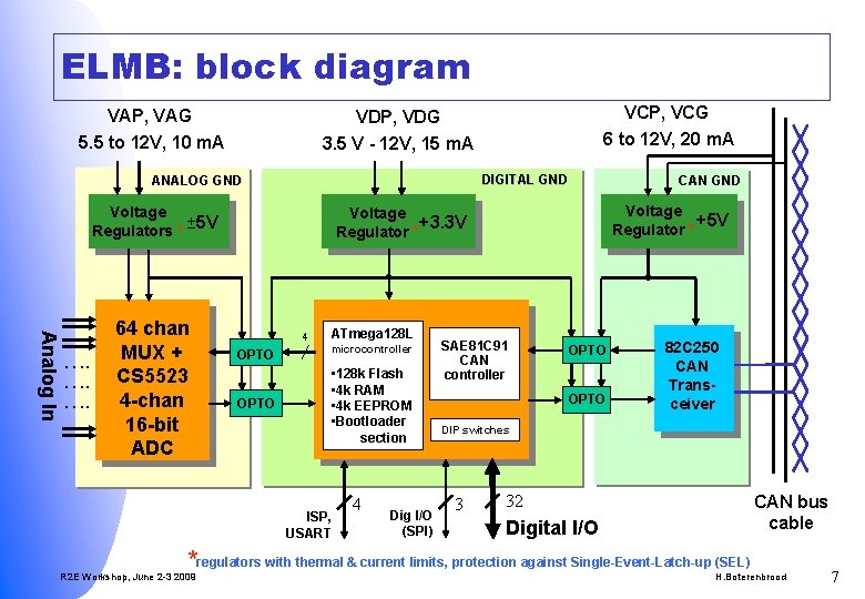
ELMB: block diagram VAP, VAG 5. 5 to 12 V, 10 m. A DIGITAL GND ANALOG GND Voltage ± 5 V Regulators * Analog In …. …. …. 64 chan MUX + CS 5523 4 -chan 16 -bit ADC VCP, VCG 6 to 12 V, 20 m. A VDP, VDG 3. 5 V - 12 V, 15 m. A Voltage +5 V Regulator * Voltage +3. 3 V Regulator * 4 OPTO ATmega 128 L microcontroller • 128 k Flash • 4 k RAM • 4 k EEPROM • Bootloader section ISP, USART 4 Dig I/O (SPI) CAN GND SAE 81 C 91 CAN controller OPTO 82 C 250 CAN Transceiver DIP switches 3 32 CAN bus cable Digital I/O *regulators with thermal & current limits, protection against Single-Event-Latch-up (SEL) R 2 E Workshop, June 2 -3 2009 H. Boterenbrood 7
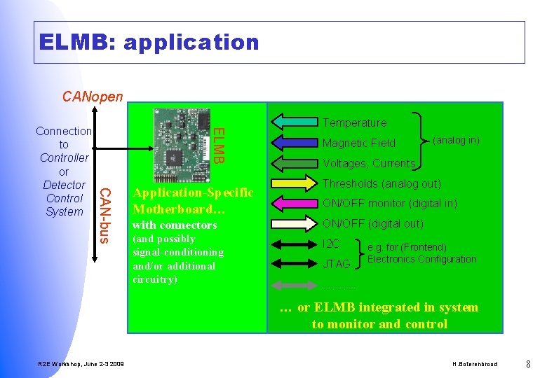
ELMB: application CANopen ELMB CAN-bus Connection to Controller or Detector Control System Application-Specific Motherboard… Temperature Magnetic Field (analog in) Voltages, Currents Thresholds (analog out) ON/OFF monitor (digital in) with connectors ON/OFF (digital out) (and possibly signal-conditioning and/or additional circuitry) I 2 C JTAG e. g. for (Frontend) Electronics Configuration ……… … or ELMB integrated in system to monitor and control R 2 E Workshop, June 2 -3 2009 H. Boterenbrood 8
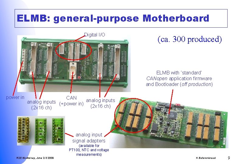
ELMB: general-purpose Motherboard Digital I/O (ca. 300 produced) ELMB with ‘standard’ CANopen application firmware and Bootloader (off production) power in CAN analog inputs (+power in) analog inputs (2 x 16 ch) analog input signal adapters R 2 E Workshop, June 2 -3 2009 (available for PT 100, NTC and voltage measurements) H. Boterenbrood 9
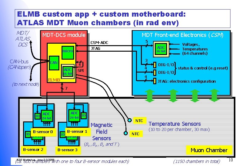
ELMB custom app + custom motherboard: ATLAS MDT Muon chambers (in rad env) MDT/ ATLAS DCS 5 CSM-ADC CAN-bus (CANopen) 4 ADC 16 -bit 4 SPI 4 ELMB (to next node) ID 16 -bit 3 CAN Voltages, Temperatures (64 channels) ADC JTAG micro ID MDT Front-end Electronics (CSM) MDT-DCS module DIG-I/O status & control (e. g reset) JTAG: electronics configuration 7 ADC 24 -bit B-sensor 0 ADC 24 -bit B-sensor 2 ID ID B-sensor 1 ADC 24 -bit Magnetic Field Sensors (Bx , By , Bz and T ) B-sensor 3 R 2 E Workshop, June 2 -3 2009 (ca. 600 chambers with one to four B-sensor modules each) NTC Temperature Sensors (10 to 20 per chamber, 30 max) Muon Chamber H. Boterenbrood (1150 chambers in total) 10
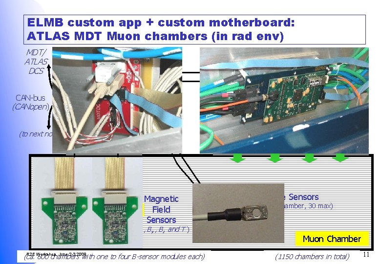
ELMB custom app + custom motherboard: ATLAS MDT Muon chambers (in rad env) MDT/ ATLAS DCS 5 CSM-ADC CAN-bus (CANopen) 4 ADC 16 -bit 4 SPI 4 ELMB (to next node) ID 16 -bit 3 CAN Voltages, Temperatures (64 channels) ADC JTAG micro ID MDT Front-end Electronics (CSM) MDT-DCS module DIG-I/O status & control (e. g reset) JTAG: electronics configuration 7 ADC 24 -bit B-sensor 0 ADC 24 -bit B-sensor 2 ID ID B-sensor 1 ADC 24 -bit Magnetic Field Sensors (Bx , By , Bz and T ) B-sensor 3 R 2 E Workshop, June 2 -3 2009 (ca. 600 chambers with one to four B-sensor modules each) NTC Temperature Sensors (10 to 20 per chamber, 30 max) Muon Chamber H. Boterenbrood (1150 chambers in total) 11
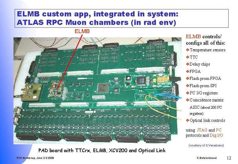
ELMB custom app, integrated in system: ATLAS RPC Muon chambers (in rad env) ELMB controls/ configs all of this: v Temperature sensors v TTC v Delay chips v FPGA v Flash prom SPI v I 2 C I/O registers v Coincidence matrix ASIC (about 200 I 2 C registers) v Optical link controls using JTAG and I 2 C protocols and Dig I/O PAD board with TTCrx, ELMB, XCV 200 and Optical Link R 2 E Workshop, June 2 -3 2009 (courtesy of S. Veneziano) H. Boterenbrood 12
More applications using ELMBs… v ATLAS § § § Muon TGC front-end electronics configuration & monitoring Silicon Tracker (SCT) Low- & High-Voltage system controller Liquid Argon Calorimeter (LAr) temperature monitor Tile Calorimeter Low-Voltage system controller and more… v Electronics rack control (all LHC experiments) v Gas flow meter read-out (all LHC experiments) v… R 2 E Workshop, June 2 -3 2009 H. Boterenbrood 13
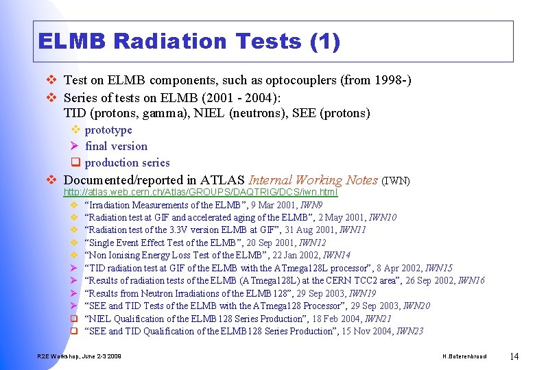
ELMB Radiation Tests (1) v Test on ELMB components, such as optocouplers (from 1998 -) v Series of tests on ELMB (2001 - 2004): TID (protons, gamma), NIEL (neutrons), SEE (protons) v prototype Ø final version q production series v Documented/reported in ATLAS Internal Working Notes (IWN) http: //atlas. web. cern. ch/Atlas/GROUPS/DAQTRIG/DCS/iwn. html v “Irradiation Measurements of the ELMB”, 9 Mar 2001, IWN 9 v “Radiation test at GIF and accelerated aging of the ELMB”, 2 May 2001, IWN 10 v “Radiation test of the 3. 3 V version ELMB at GIF”, 31 Aug 2001, IWN 11 v “Single Event Effect Test of the ELMB”, 20 Sep 2001, IWN 12 v “Non Ionising Energy Loss Test of the ELMB”, 22 Jan 2002, IWN 14 Ø “TID radiation test at GIF of the ELMB with the ATmega 128 L processor”, 8 Apr 2002, IWN 15 Ø “Results of radiation tests of the ELMB (ATmega 128 L) at the CERN TCC 2 area”, 26 Sep 2002, IWN 16 Ø “Results from Neutron Irradiations of the ELMB 128”, 29 Sep 2003, IWN 19 Ø “SEE and TID Tests of the ELMB with the ATmega 128 Processor”, 29 Sep 2003, IWN 20 q “NIEL Qualification of the ELMB 128 Series Production”, 18 Feb 2004, IWN 21 q “SEE and TID Qualification of the ELMB 128 Series Production”, 15 Nov 2004, IWN 23 R 2 E Workshop, June 2 -3 2009 H. Boterenbrood 14
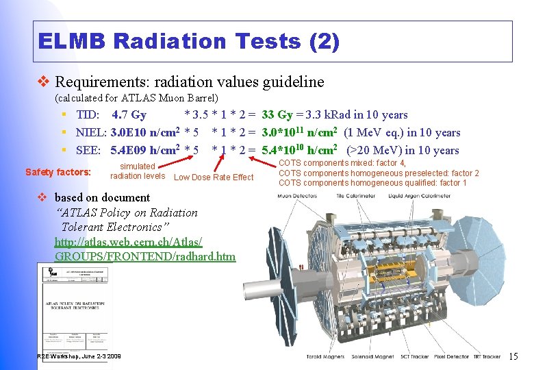
ELMB Radiation Tests (2) v Requirements: radiation values guideline (calculated for ATLAS Muon Barrel) § TID: 4. 7 Gy * 3. 5 * 1 * 2 = 33 Gy = 3. 3 k. Rad in 10 years § NIEL: 3. 0 E 10 n/cm 2 * 5 * 1 * 2 = 3. 0*1011 n/cm 2 (1 Me. V eq. ) in 10 years § SEE: 5. 4 E 09 h/cm 2 * 5 * 1 * 2 = 5. 4*1010 h/cm 2 (>20 Me. V) in 10 years Safety factors: simulated radiation levels Low Dose Rate Effect COTS components mixed: factor 4, COTS components homogeneous preselected: factor 2 COTS components homogeneous qualified: factor 1 v based on document “ATLAS Policy on Radiation Tolerant Electronics” http: //atlas. web. cern. ch/Atlas/ GROUPS/FRONTEND/radhard. htm R 2 E Workshop, June 2 -3 2009 H. Boterenbrood 15
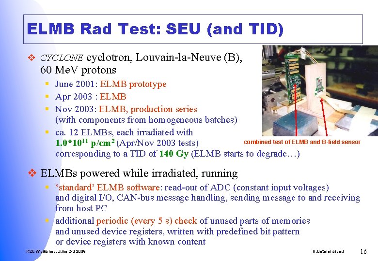
ELMB Rad Test: SEU (and TID) v CYCLONE cyclotron, Louvain-la-Neuve (B), 60 Me. V protons § June 2001: ELMB prototype § Apr 2003 : ELMB § Nov 2003: ELMB, production series (with components from homogeneous batches) § ca. 12 ELMBs, each irradiated with combined test of ELMB and B-field sensor 1. 0*1011 p/cm 2 (Apr/Nov 2003 tests) corresponding to a TID of 140 Gy (ELMB starts to degrade…) v ELMBs powered while irradiated, running § ‘standard’ ELMB software: read-out of ADC (constant input voltages) and digital I/O, CAN-bus message handling, sending message to and receiving from host PC § additional periodic (every 5 s) check of unused parts of memories and unused device registers, written with predefined bit pattern or device registers with known content R 2 E Workshop, June 2 -3 2009 H. Boterenbrood 16
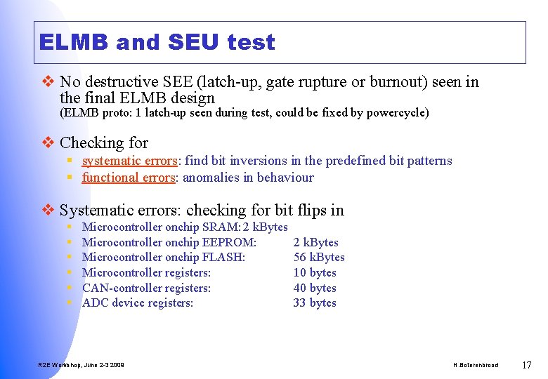
ELMB and SEU test v No destructive SEE (latch-up, gate rupture or burnout) seen in the final ELMB design (ELMB proto: 1 latch-up seen during test, could be fixed by powercycle) v Checking for § systematic errors: find bit inversions in the predefined bit patterns § functional errors: anomalies in behaviour v Systematic errors: checking for bit flips in § § § Microcontroller onchip SRAM: 2 k. Bytes Microcontroller onchip EEPROM: Microcontroller onchip FLASH: Microcontroller registers: CAN-controller registers: ADC device registers: R 2 E Workshop, June 2 -3 2009 2 k. Bytes 56 k. Bytes 10 bytes 40 bytes 33 bytes H. Boterenbrood 17
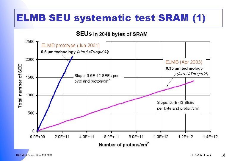
ELMB SEU systematic test SRAM (1) SEUs ELMB prototype (Jun 2001) (Atmel ATmega 103) ELMB (Apr 2003) (Atmel ATmega 128) R 2 E Workshop, June 2 -3 2009 H. Boterenbrood 18
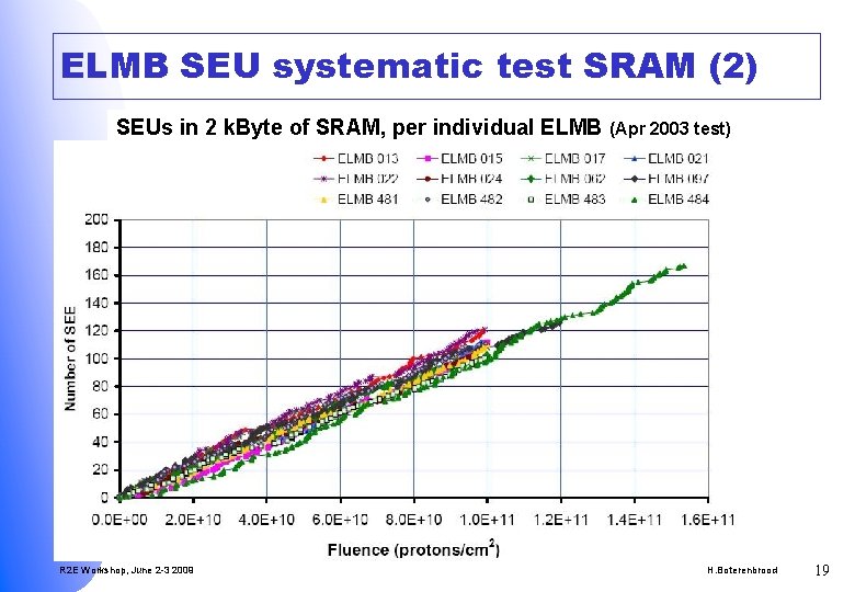
ELMB SEU systematic test SRAM (2) SEUs in 2 k. Byte of SRAM, per individual ELMB R 2 E Workshop, June 2 -3 2009 (Apr 2003 test) H. Boterenbrood 19
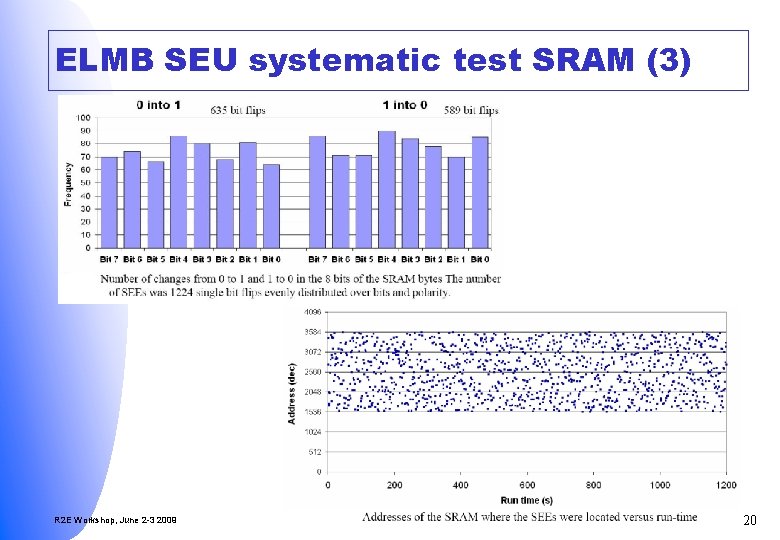
ELMB SEU systematic test SRAM (3) R 2 E Workshop, June 2 -3 2009 H. Boterenbrood 20
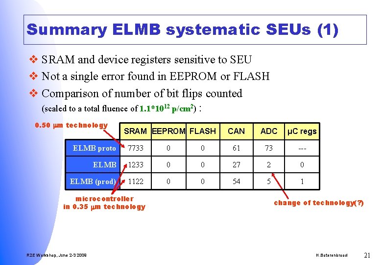
Summary ELMB systematic SEUs (1) v SRAM and device registers sensitive to SEU v Not a single error found in EEPROM or FLASH v Comparison of number of bit flips counted (scaled to a total fluence of 1. 1*1012 p/cm 2) : 0. 50 m technology SRAM EEPROM FLASH CAN ADC μC regs ELMB proto 7733 0 0 61 73 --- ELMB 1233 0 0 27 2 0 ELMB (prod) 1122 0 0 54 5 1 microcontroller in 0. 35 m technology R 2 E Workshop, June 2 -3 2009 change of technology(? ) H. Boterenbrood 21
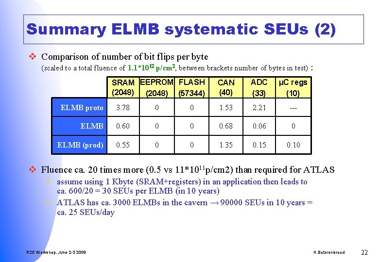
Summary ELMB systematic SEUs (2) v Comparison of number of bit flips per byte (scaled to a total fluence of 1. 1*1012 p/cm 2, between brackets number of bytes in test) : SRAM EEPROM FLASH (2048) (57344) CAN (40) ADC (33) μC regs (10) ELMB proto 3. 78 0 0 1. 53 2. 21 --- ELMB 0. 60 0 0 0. 68 0. 06 0 ELMB (prod) 0. 55 0 0 1. 35 0. 10 v Fluence ca. 20 times more (0. 5 vs 11*1011 p/cm 2) than required for ATLAS § assume using 1 Kbyte (SRAM+registers) in an application then leads to ca. 600/20 = 30 SEUs per ELMB (in 10 years) § ATLAS has ca. 3000 ELMBs in the cavern → 90000 SEUs in 10 years = ca. 25 SEUs/day R 2 E Workshop, June 2 -3 2009 H. Boterenbrood 22
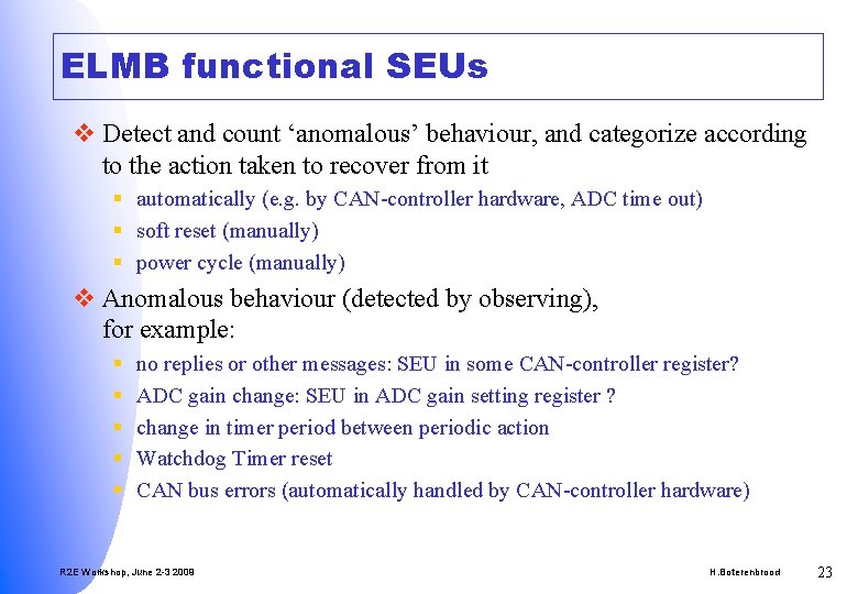
ELMB functional SEUs v Detect and count ‘anomalous’ behaviour, and categorize according to the action taken to recover from it § automatically (e. g. by CAN-controller hardware, ADC time out) § soft reset (manually) § power cycle (manually) v Anomalous behaviour (detected by observing), for example: § § § no replies or other messages: SEU in some CAN-controller register? ADC gain change: SEU in ADC gain setting register ? change in timer period between periodic action Watchdog Timer reset CAN bus errors (automatically handled by CAN-controller hardware) R 2 E Workshop, June 2 -3 2009 H. Boterenbrood 23
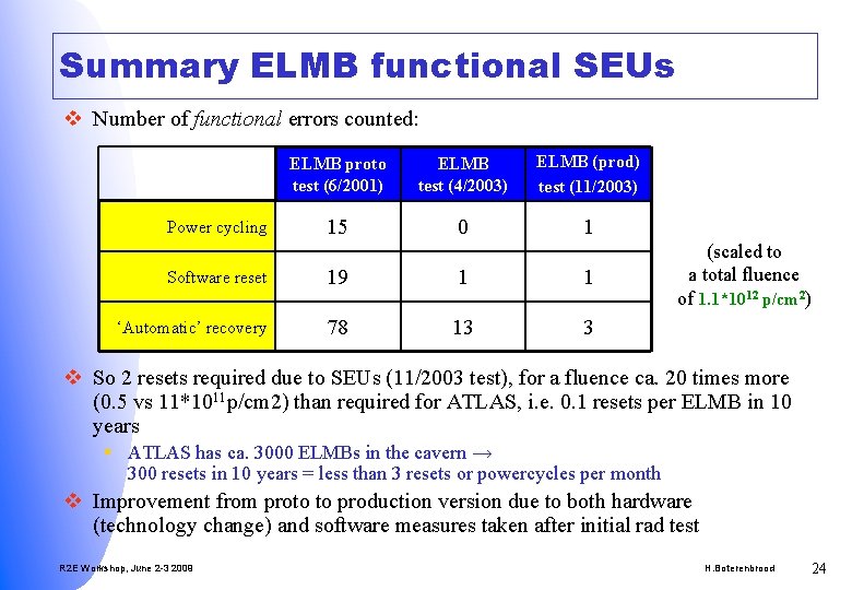
Summary ELMB functional SEUs v Number of functional errors counted: Power cycling ELMB proto test (6/2001) ELMB test (4/2003) ELMB (prod) test (11/2003) 15 0 1 Software reset 19 1 1 ‘Automatic’ recovery 78 13 3 (scaled to a total fluence of 1. 1*1012 p/cm 2) v So 2 resets required due to SEUs (11/2003 test), for a fluence ca. 20 times more (0. 5 vs 11*1011 p/cm 2) than required for ATLAS, i. e. 0. 1 resets per ELMB in 10 years § ATLAS has ca. 3000 ELMBs in the cavern → 300 resets in 10 years = less than 3 resets or powercycles per month v Improvement from proto to production version due to both hardware (technology change) and software measures taken after initial rad test R 2 E Workshop, June 2 -3 2009 H. Boterenbrood 24
ELMB software and SEU v Knowing that § EEPROM (and Flash) is not sensitive to SEU § SRAM and device registers are sensitive to SEU v Write the software such as to take this into account to try to minimize the impact of SEUs on the ELMB’s operation § points listed in the next slides in more or less arbitrary order R 2 E Workshop, June 2 -3 2009 H. Boterenbrood 25
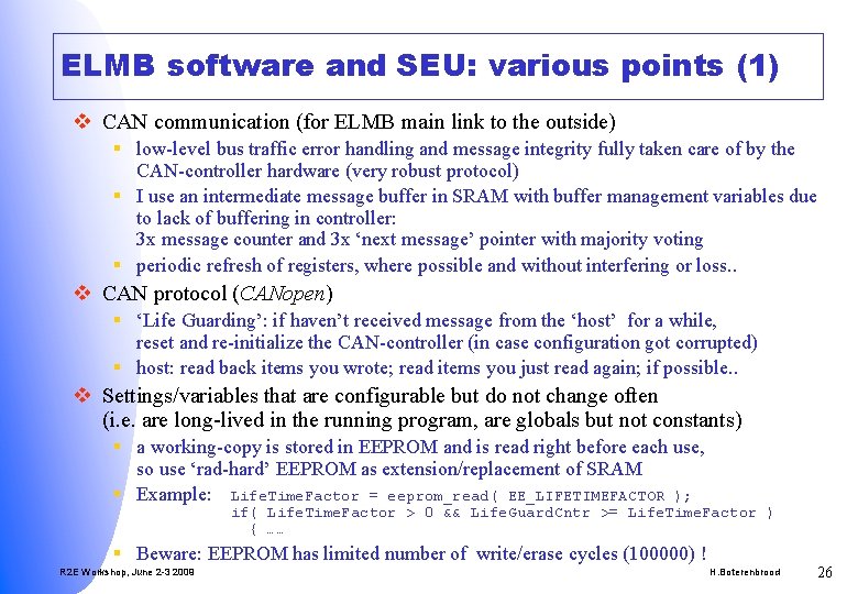
ELMB software and SEU: various points (1) v CAN communication (for ELMB main link to the outside) § low-level bus traffic error handling and message integrity fully taken care of by the CAN-controller hardware (very robust protocol) § I use an intermediate message buffer in SRAM with buffer management variables due to lack of buffering in controller: 3 x message counter and 3 x ‘next message’ pointer with majority voting § periodic refresh of registers, where possible and without interfering or loss. . v CAN protocol (CANopen) § ‘Life Guarding’: if haven’t received message from the ‘host’ for a while, reset and re-initialize the CAN-controller (in case configuration got corrupted) § host: read back items you wrote; read items you just read again; if possible. . v Settings/variables that are configurable but do not change often (i. e. are long-lived in the running program, are globals but not constants) § a working-copy is stored in EEPROM and is read right before each use, so use ‘rad-hard’ EEPROM as extension/replacement of SRAM § Example: Life. Time. Factor = eeprom_read( EE_LIFETIMEFACTOR ); if( Life. Time. Factor > 0 && Life. Guard. Cntr >= Life. Time. Factor ) { …… § Beware: EEPROM has limited number of write/erase cycles (100000) ! R 2 E Workshop, June 2 -3 2009 H. Boterenbrood 26
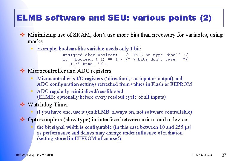
ELMB software and SEU: various points (2) v Minimizing use of SRAM, don’t use more bits than necessary for variables, using masks § Example, boolean-like variable needs only 1 bit: unsigned char boolean; /* In C no type ‘bool’ */ if( (boolean & 1) == 1 ) /* 7 bits don’t care */ { /* true… */ } v Microcontroller and ADC registers § Microcontroller’s I/O registers (‘direction’, i. e. input or output) and ADC configuration settings refreshed from values in Flash or EEPROM § ADC regularly reinitialized/recalibrated (ELMB: optionally before every readout cycle of all inputs) v Watchdog Timer § if you have one, use it (on ELMB: always on, not software controllable) v Opto-couplers (slow type) in interface between micro and a device § the bit signal width is configurable (in this case between 10 and 255 μs) as performance and delays may change under influence of radiation (setting stored in EEPROM of course!) R 2 E Workshop, June 2 -3 2009 H. Boterenbrood 27
ELMB software and SEU: various points (3 ) v Some additional notes § avoid to take a (drastic) decision based on a single reading § try to avoid writing to EEPROM (i. e. change the configuration of the ELMB app) during radiation, since stuff in ELMB EEPROM is now considered error-free, reliable data § remote in-system-programming very useful because bugs and unanticipated ‘effects’ can be fixed • beware: flash programming capability deteriorates due to radiation, so a working module can be ‘killed’ trying to upgrade/reprogram it • ELMB power-up: Bootloader (= flash upgrade app) is active for a few seconds, allowing upgrade even when user application is corrupt • don’t upgrade during radiation § now we wait for LHC to come online and see what happens… R 2 E Workshop, June 2 -3 2009 H. Boterenbrood 28
Conclusion v ELMB qualified for radiation environment up to certain levels – exceeding the requirements– by extensive and rigorous testing, including TID, NIEL and SEE v ELMB sensitivity to SEUs considered more than acceptable (but not for safety-critical applications in the cavern…) v Coding practices in the ELMB software contribute to more radiation-tolerant behaviour of the embedded application software with respect to SEUs v References § ATLAS rad-hard electronics webpage http: //atlas. web. cern. ch/Atlas/GROUPS/FRONTEND/radhard. htm § ELMB info: documentation, schematics, source code http: //elmb. web. cern. ch § ELMB rad tests reports http: //atlas. web. cern. ch/Atlas/GROUPS/DAQTRIG/DCS/iwn. html R 2 E Workshop, June 2 -3 2009 H. Boterenbrood 29
Key Messages v The ELMB is composed of standard COTS components, no special rad-tolerant or rad-hard components were used. v A lot of effort and preparation goes into radiation tests on a hardware module plus its software, such as the ELMB, which -in fact- is actually a fairly simple module, and still only part of a larger system. v Changing a component in the design or a change of technology by the component manufacturer may have a large impact on the SEU sensitivity of a module design, so radiation tests should be repeated (example: change of processor type on the ELMB). v In the SEU tests of the ELMB we found that SEUs occur in SRAM and device registers. The software has been written with a number of adaptations to take this into account, such as a majority voting scheme, register refresh, and others. v In the SEU tests of the ELMB we did not find any SEUs in EEPROM or FLASH memory. The software has been adapted to take advantage of this fact by using the EEPROM as a kind of rad -tolerant extension to the SRAM for storing long-lived variables. v The extra precautions taken in writing the ELMB software have contributed to mitigate the effects of SEUs in the module and increase the overall tolerance of the ELMB to SEUs. R 2 E Workshop, June 2 -3 2009 H. Boterenbrood 30
- Slides: 30