
Session 5 Design of a Solar Water Scheme


- Slides: 18
Session 5 Design of a Solar Water Scheme Refresher Juba Workshop 17 th – 18 th July 2017 Mainstreaming the use of solar PV technology in WASH projects
Designing a Solar Water Scheme § Over design – Expensive § Under design – Insufficient performance § Correct Sizing – desired performance, reliability, durability § Considerations – Duty requirement, Available flow, Power Source, Water Storage, configuration Majority of failures are as a result of poor borehole siting, construction, wrong dimensioning, installation
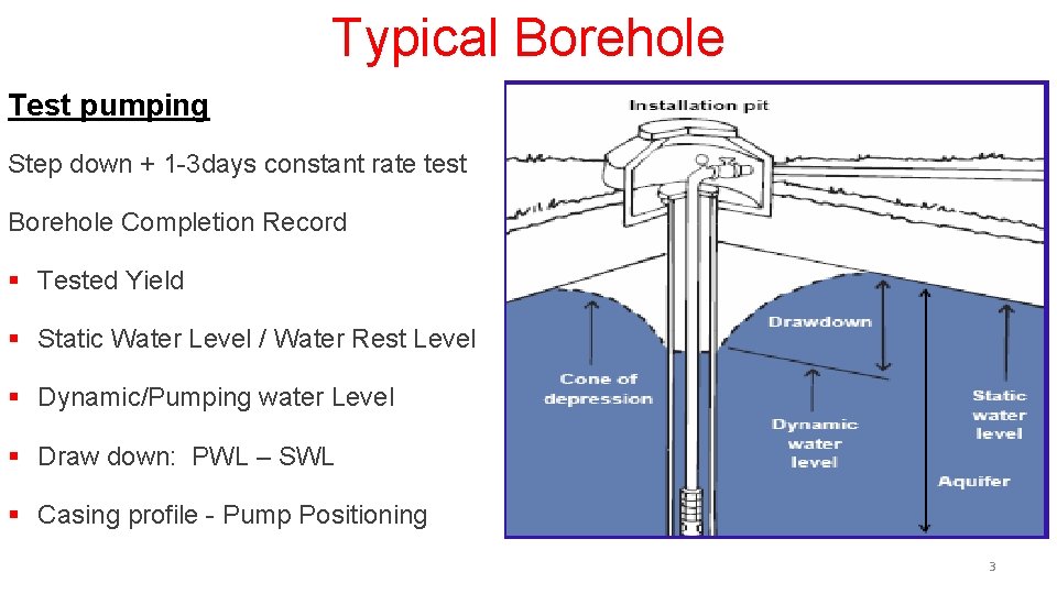
Typical Borehole Test pumping Step down + 1 -3 days constant rate test Borehole Completion Record § Tested Yield § Static Water Level / Water Rest Level § Dynamic/Pumping water Level § Draw down: PWL – SWL § Casing profile - Pump Positioning 3
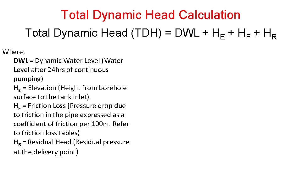
Total Dynamic Head Calculation Total Dynamic Head (TDH) = DWL + HE + HF + HR Where; DWL = Dynamic Water Level (Water Level after 24 hrs of continuous pumping) HE = Elevation (Height from borehole surface to the tank inlet) HF = Friction Loss (Pressure drop due to friction in the pipe expressed as a coefficient of friction per 100 m. Refer to friction loss tables) HR = Residual Head (Residual pressure at the delivery point)
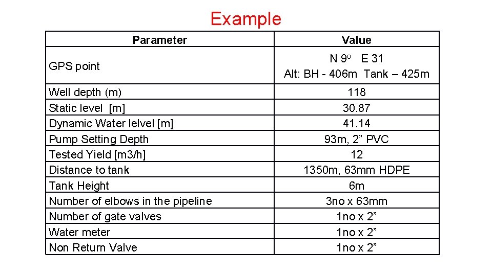
Example Parameter GPS point Well depth (m) Static level [m] Dynamic Water lelvel [m] Pump Setting Depth Tested Yield [m 3/h] Distance to tank Tank Height Number of elbows in the pipeline Number of gate valves Water meter Non Return Valve Value N 9 o E 31 Alt: BH - 406 m Tank – 425 m 118 30. 87 41. 14 93 m, 2” PVC 12 1350 m, 63 mm HDPE 6 m 3 no x 63 mm 1 no x 2”
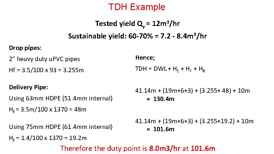
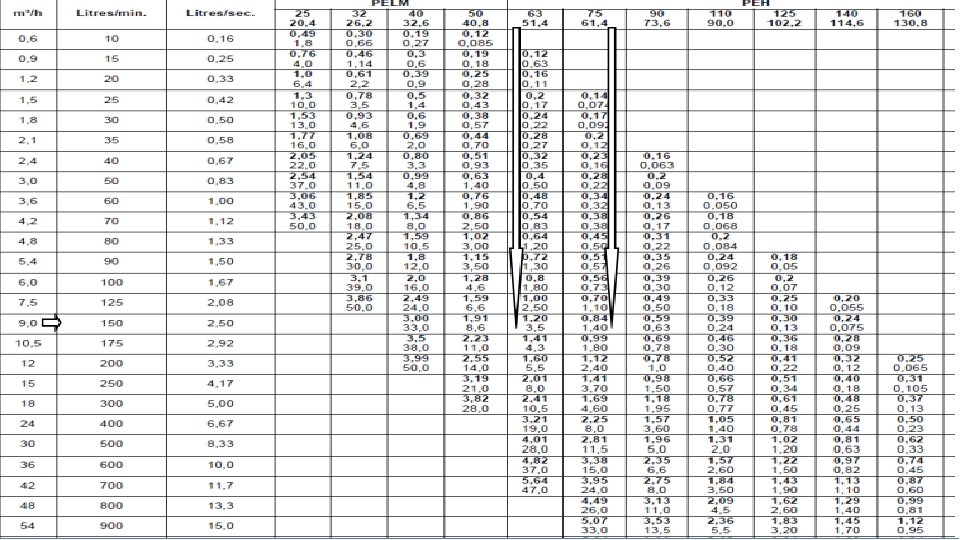
TDH Example Tested yield Qy = 12 m 3/hr Sustainable yield: 60 -70% = 7. 2 - 8. 4 m 3/hr Drop pipes: 2” heavy duty u. PVC pipes Hence; Hf = 3. 5/100 x 93 = 3. 255 m TDH = DWL + HE + HF + HR Delivery Pipe: 41. 14 m + (19 m+6+3) + (3. 255+ 48) + 10 m = 130. 4 m Using 63 mm HDPE (51. 4 mm internal) Hf = 3. 5 m/100 x 1370 = 48 m Using 75 mm HDPE (61. 4 mm internal) 41. 14 m + (19 m+6+3) + (3. 255+19. 2) + 10 m = 101. 6 m Hf = 1. 4/100 x 1370 = 19. 2 m Therefore the duty point is 8. 0 m 3/hr at 101. 6 m
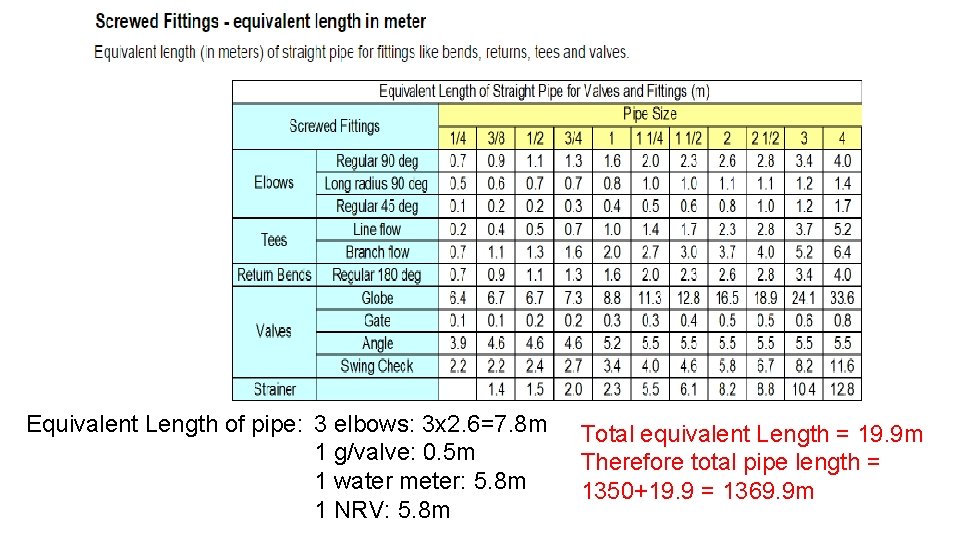
Equivalent Length of pipe: 3 elbows: 3 x 2. 6=7. 8 m 1 g/valve: 0. 5 m 1 water meter: 5. 8 m 1 NRV: 5. 8 m Total equivalent Length = 19. 9 m Therefore total pipe length = 1350+19. 9 = 1369. 9 m
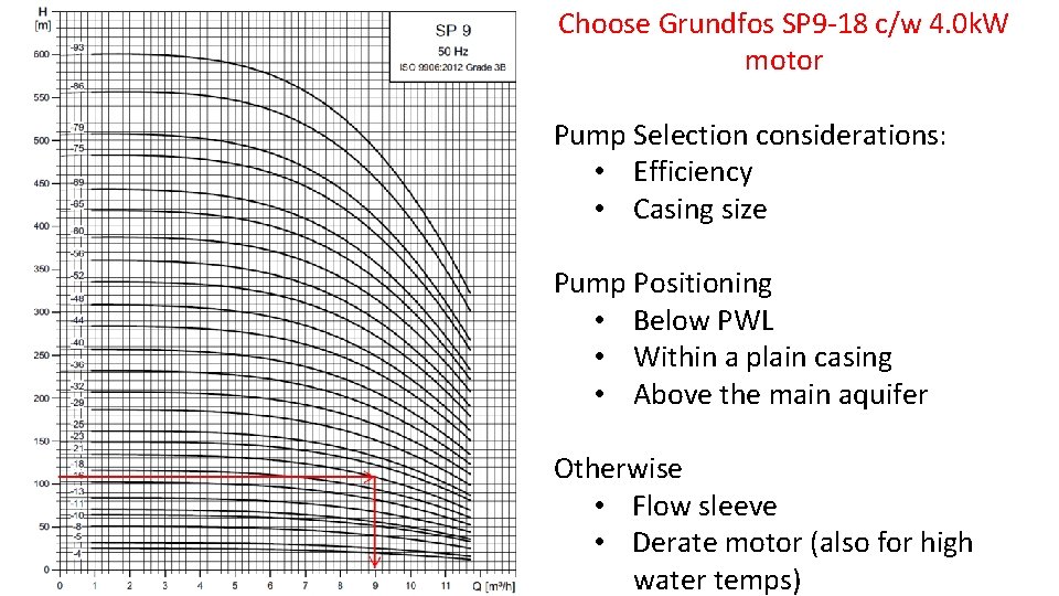
Choose Grundfos SP 9 -18 c/w 4. 0 k. W motor Pump Selection considerations: • Efficiency • Casing size Pump Positioning • Below PWL • Within a plain casing • Above the main aquifer Otherwise • Flow sleeve • Derate motor (also for high water temps)
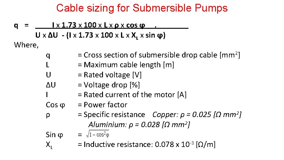
Cable sizing for Submersible Pumps q = I x 1. 73 x 100 x L x ρ x cos ϕ . U x ∆U - (I x 1. 73 x 100 x L x XL x sin ϕ) Where, q = Cross section of submersible drop cable [mm 2] L = Maximum cable length [m] U = Rated voltage [V] ∆U = Voltage drop [%] I = Rated current of the motor [A] Cos ϕ = Power factor ρ = Specific resistance Copper: ρ = 0. 025 [Ω mm 2] Aluminium: ρ = 0. 028 [Ω mm 2] Sin ϕ = XL = Inductive resistance: 0. 078 x 10 -3 [Ω/m]
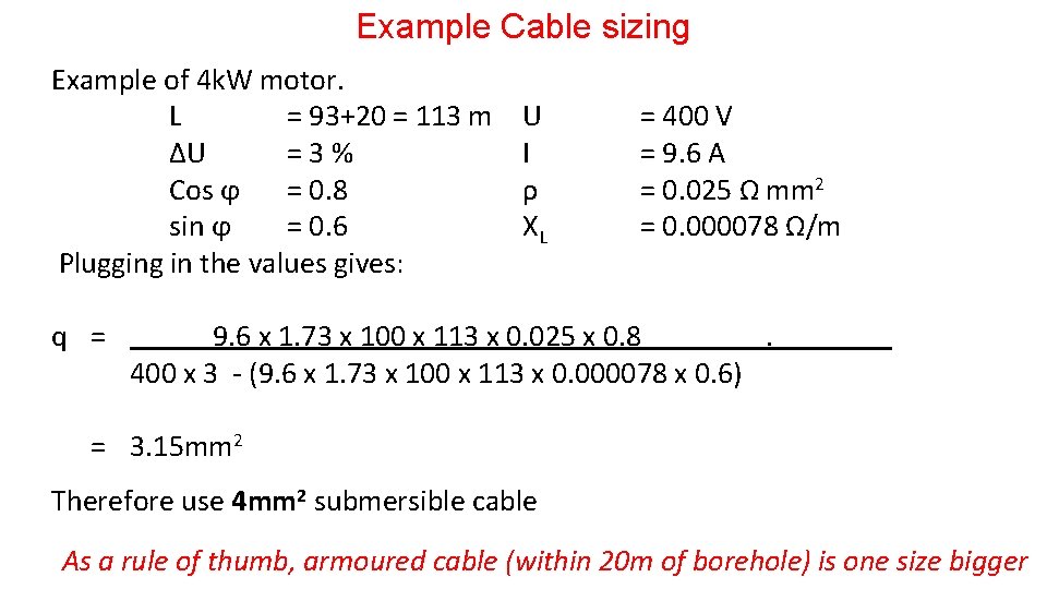
Example Cable sizing Example of 4 k. W motor. L = 93+20 = 113 m U = 400 V ∆U = 3 % I = 9. 6 A Cos ϕ = 0. 8 ρ = 0. 025 Ω mm 2 sin ϕ = 0. 6 XL = 0. 000078 Ω/m Plugging in the values gives: q = 9. 6 x 1. 73 x 100 x 113 x 0. 025 x 0. 8 . 400 x 3 - (9. 6 x 1. 73 x 100 x 113 x 0. 000078 x 0. 6) = 3. 15 mm 2 Therefore use 4 mm 2 submersible cable As a rule of thumb, armoured cable (within 20 m of borehole) is one size bigger
Example Cable sizing
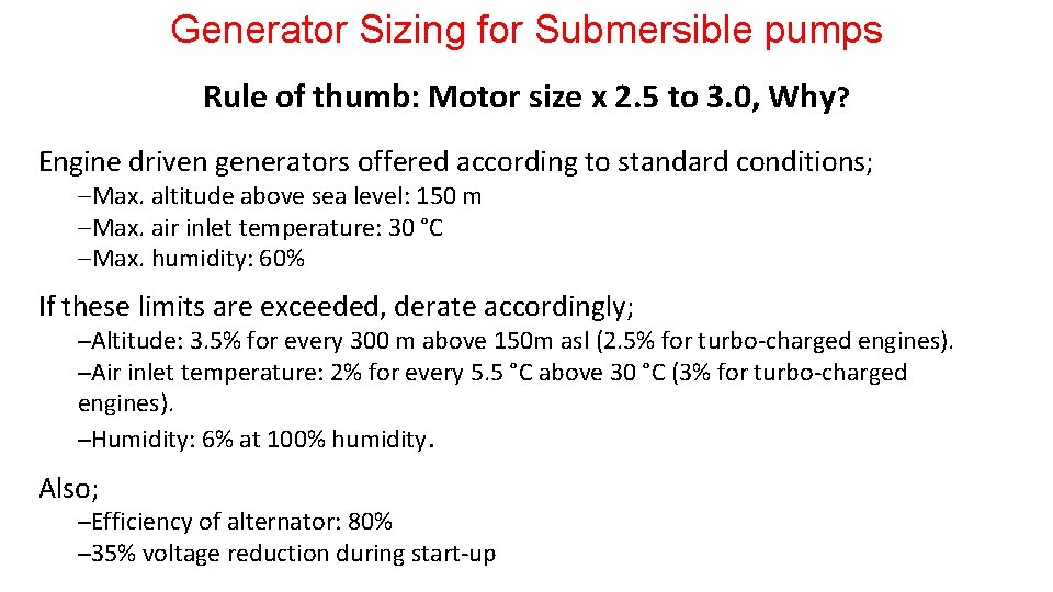
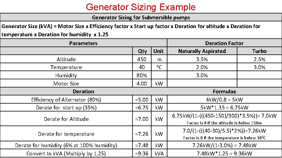
Generator Sizing for Submersible pumps Rule of thumb: Motor size x 2. 5 to 3. 0, Why? Engine driven generators offered according to standard conditions; Max. altitude above sea level: 150 m Max. air inlet temperature: 30 °C Max. humidity: 60% If these limits are exceeded, derate accordingly; ─Altitude: 3. 5% for every 300 m above 150 m asl (2. 5% for turbo-charged engines). ─Air inlet temperature: 2% for every 5. 5 °C above 30 °C (3% for turbo-charged engines). ─Humidity: 6% at 100% humidity. Also; ─Efficiency of alternator: 80% ─35% voltage reduction during start-up
Generator Sizing Example Generator Sizing for Submersible pumps Generator Size (k. VA) = Motor Size x Efficiency factor x Start up factor x Deration for altitude x Deration for temperature x Deration for humidity x 1. 25 Parameters Deration Factor Qty Unit Naturally Aspirated Turbo Altitude 450 m 3. 5% 2. 5% 0 C Temperature 40 2. 0% 3. 0% Humidity 80% 3. 0% Motor Size 4. 00 k. W Deration Formulae Efficiency of Alternator (80%) =5. 00 k. W 4 k. W/0. 8 = 5 k. W Derate for start up (35%) =6. 75 k. W 5 k. W*1. 35 = 6. 75 k. W/(1 -(((450 -150)/300)*3. 5%))= 7. 0 k. W Derate for Altitude =7. 00 k. W Factor is 0 if the altitude is below 150 m Derate for temperature =7. 26 k. W Derate for humidity (6% at 100% humidity) Convert to k. VA (Multiply by 1. 25) =7. 48 =9. 36 k. W k. VA 7. 0/(1 -(((40 -30)/5. 5)*2%))=7. 26 k. W Factor is 0 if the temperature is below 300 C 7. 26 k. W/(1 -3. 0%) = 7. 48 k. W*1. 25 = 9. 36 k. W
Coffee Break
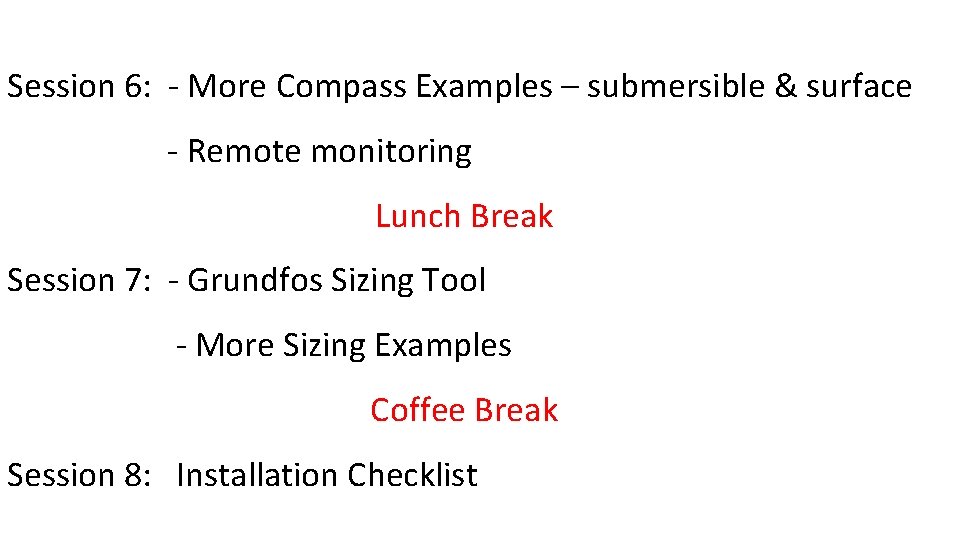
Session 6: - More Compass Examples – submersible & surface - Remote monitoring Lunch Break Session 7: - Grundfos Sizing Tool - More Sizing Examples Coffee Break Session 8: Installation Checklist
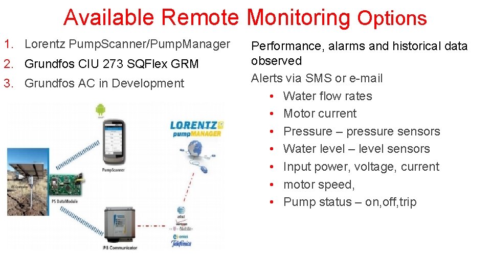
Available Remote Monitoring Options 1. Lorentz Pump. Scanner/Pump. Manager 2. Grundfos CIU 273 SQFlex GRM 3. Grundfos AC in Development Performance, alarms and historical data observed Alerts via SMS or e-mail • Water flow rates • Motor current • Pressure – pressure sensors • Water level – level sensors • Input power, voltage, current • motor speed, • Pump status – on, off, trip
Thank you for your attention. Contact: solarquery@iom. int