
Services RE 3 41 Ian on behalf of
Services RE 3 & 4/1 Ian on behalf of the RPC Group 5 Sept 2018
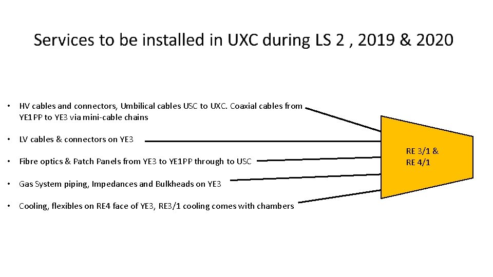
• HV cables and connectors, Umbilical cables USC to UXC. Coaxial cables from YE 1 PP to YE 3 via mini-cable chains • LV cables & connectors on YE 3 • Fibre optics & Patch Panels from YE 3 to YE 1 PP through to USC • Gas System piping, Impedances and Bulkheads on YE 3 • Cooling, flexibles on RE 4 face of YE 3, RE 3/1 cooling comes with chambers RE 3/1 & RE 4/1

HV System in UXC We have selected a coaxial connector, tested over many years, namely the C. P. E. “Jupiter” coaxial connector. The order for the cables and connectors is ready, only awaiting the choice of dielectric. The cables will be QA in the company under our supervision and retested in 904. Commissioning will be enhanced with resistances in boxes, simulating the chamber load, placed in place of the chambers.
HV System in the USC A new rack, S 1 H 12, is installed for the RE 3/1 and RE 4/1 components. The TDR version, an extension of the present system is planned. However an alternative preferred version is planned for testing in 2019 Layout from Anton with calculation of components. Which ever solution is finally taken does not influence the cabling from UXC.
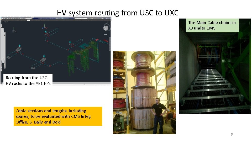
HV system routing from USC to UXC The Main Cable chains in X 0 under CMS Routing from the USC HV racks to the YE 1 PPs Cable sections and lengths, including spares, to be evaluated with CMS Integ Office, S. Bally and Boki 5
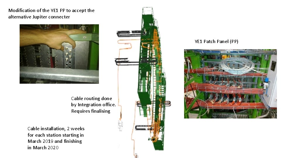
Modification of the YE 1 PP to accept the alternative Jupiter connecter YE 1 Patch Panel (PP) Cable routing done by Integration office. Requires finalising Cable installation, 2 weeks for each station starting in March 2019 and finishing in March 2020
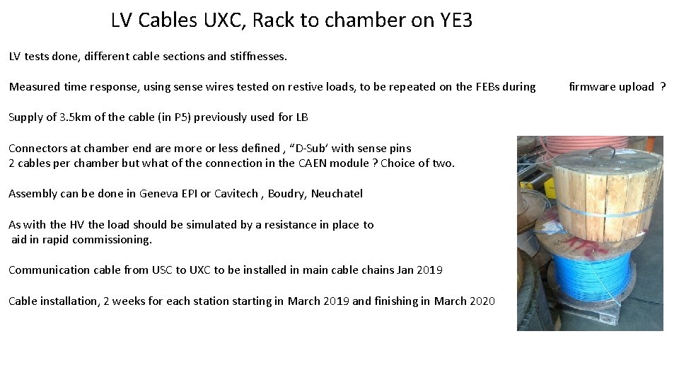
LV Cables UXC, Rack to chamber on YE 3 LV tests done, different cable sections and stiffnesses. Measured time response, using sense wires tested on restive loads, to be repeated on the FEBs during Supply of 3. 5 km of the cable (in P 5) previously used for LB Connectors at chamber end are more or less defined , “D-Sub’ with sense pins 2 cables per chamber but what of the connection in the CAEN module ? Choice of two. Assembly can be done in Geneva EPI or Cavitech , Boudry, Neuchatel As with the HV the load should be simulated by a resistance in place to aid in rapid commissioning. Communication cable from USC to UXC to be installed in main cable chains Jan 2019 Cable installation, 2 weeks for each station starting in March 2019 and finishing in March 2020 firmware upload ?
Fibre optics. • From the choice between Blown fibres and Trunk cables, we have taken the latter, with approval from TC. • As the main protagonists, Zhenan and Behzad are here at CERN we will come out with a full spec by end of next week • The order should leave CERN before the end of September. • Fibres to be installed in week 5 of 2019
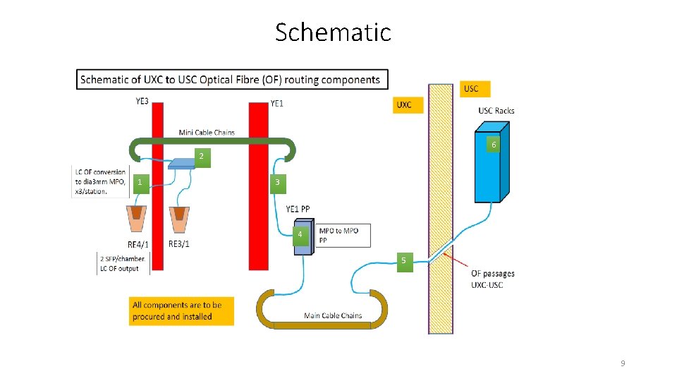
Schematic 6 2 1 3 4 5 9
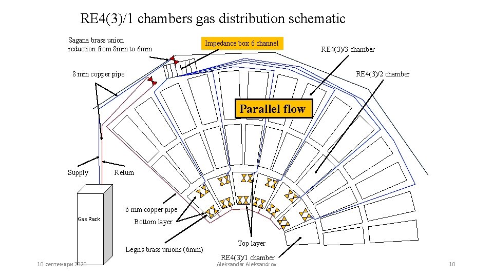
RE 4(3)/1 chambers gas distribution schematic Sagana brass union reduction from 8 mm to 6 mm Impedance box 6 channel RE 4(3)/3 chamber RE 4(3)/2 chamber 8 mm copper pipe Parallel flow Supply Return 6 mm copper pipe Gas Rack Bottom layer Legris brass unions (6 mm) 10 септември 2020 Top layer RE 4(3)/1 chamber Aleksandar Aleksandrov 10
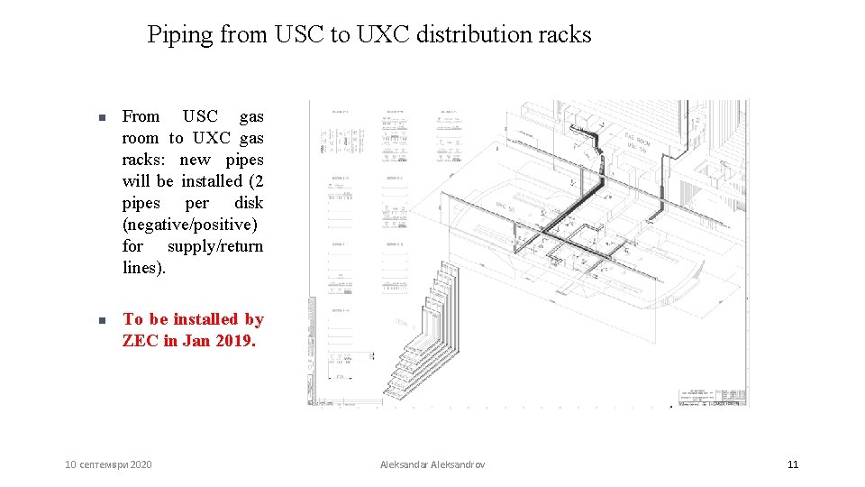
Piping from USC to UXC distribution racks n n From USC gas room to UXC gas racks: new pipes will be installed (2 pipes per disk (negative/positive) for supply/return lines). To be installed by ZEC in Jan 2019. 10 септември 2020 Aleksandar Aleksandrov 11
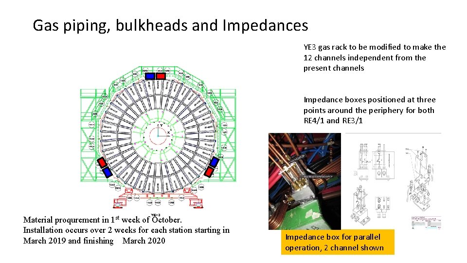
Gas piping, bulkheads and Impedances YE 3 gas rack to be modified to make the 12 channels independent from the present channels Impedance boxes positioned at three points around the periphery for both RE 4/1 and RE 3/1 Material proqurement in 1 st week of October. Installation occurs over 2 weeks for each station starting in March 2019 and finishing March 2020 Impedance box for parallel operation, 2 channel shown
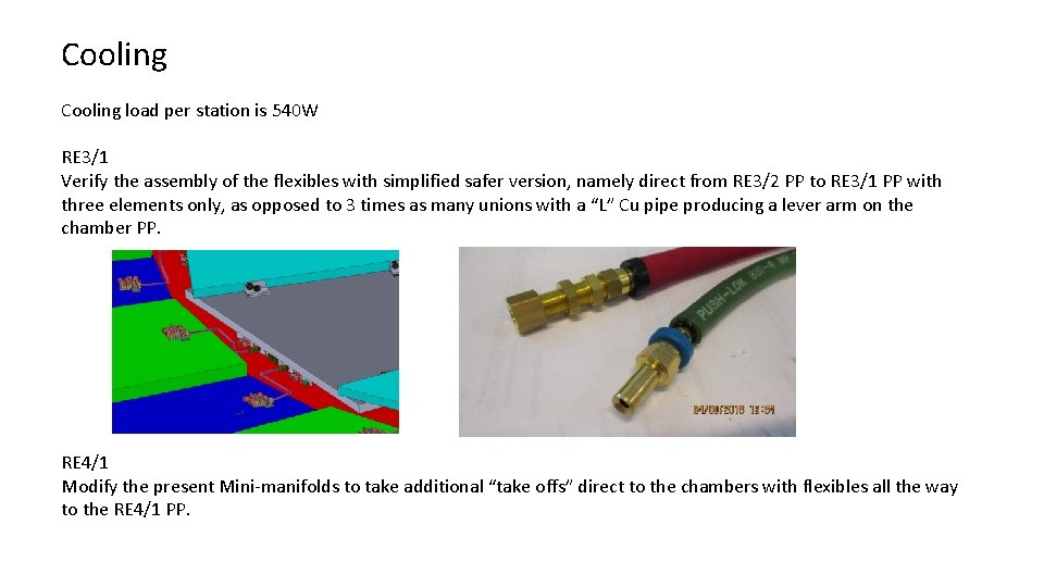
Cooling load per station is 540 W RE 3/1 Verify the assembly of the flexibles with simplified safer version, namely direct from RE 3/2 PP to RE 3/1 PP with three elements only, as opposed to 3 times as many unions with a “L” Cu pipe producing a lever arm on the chamber PP. RE 4/1 Modify the present Mini-manifolds to take additional “take offs” direct to the chambers with flexibles all the way to the RE 4/1 PP.
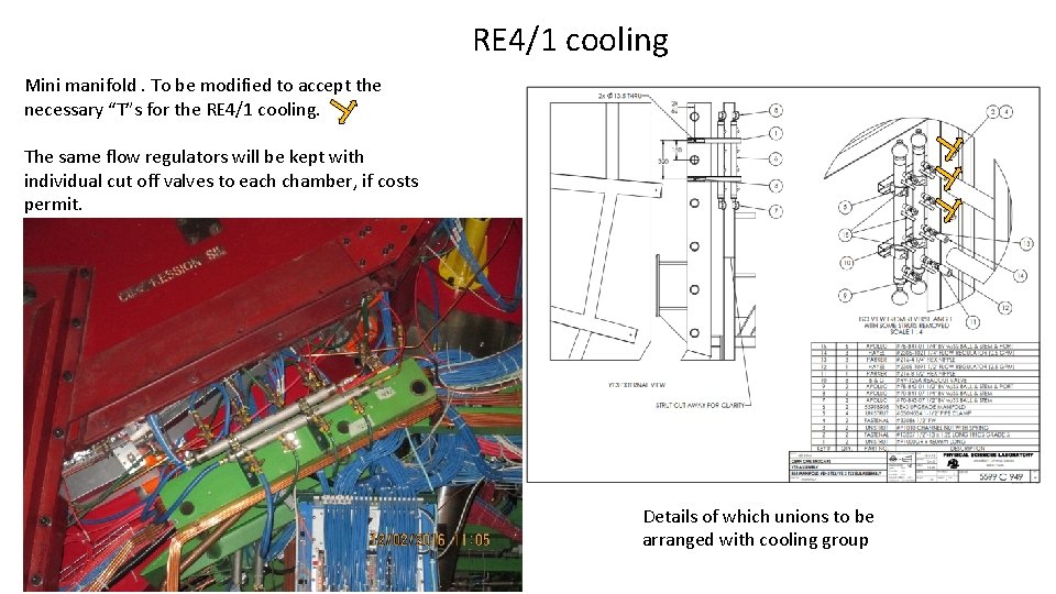
RE 4/1 cooling Mini manifold. To be modified to accept the necessary “T”s for the RE 4/1 cooling. The same flow regulators will be kept with individual cut off valves to each chamber, if costs permit. Details of which unions to be arranged with cooling group
Actions required • HV. Outstanding points with CPE, assembly QC methods and timeline • LV • Do test with New FEB while loading firmware and max cable length ~30 m • S. Bally for exact cable lengths • Contact Houari for cable length in P 5 store. • Fibres, check where we are with spec and supplier in next 10 days as Bezhad and Zhenan are here. • Check procurement details with Austin. • Gas requires details drawing for installation. • See with cooling suppliers for the inch size on “T” mini manifolds and the metric on the chamber.

Additional Material

https: //www. epi. ge. ch/prestations-entreprisesparticuliers/ateliers/microtechnique/
RPC Power System Review Anton Dimitrov, Ian Crotty RPC Upgrade Mini Workshop, 05. Sep. 2018, CERN
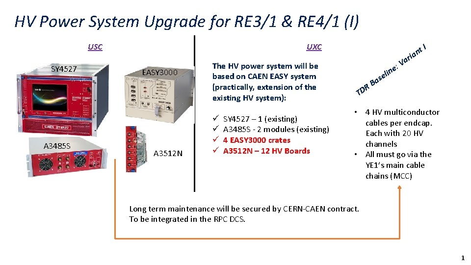
HV Power System Upgrade for RE 3/1 & RE 4/1 (I) USC SY 4527 A 3485 S UXC EASY 3000 A 3512 N The HV power system will be based on CAEN EASY system (practically, extension of the existing HV system): ü ü SY 4527 – 1 (existing) A 3485 S - 2 modules (existing) 4 EASY 3000 crates A 3512 N – 12 HV Boards s TD a B R e n eli t n a i I r a : V • 4 HV multiconductor cables per endcap. Each with 20 HV channels • All must go via the YE 1’s main cable chains (MCC) Long term maintenance will be secured by CERN-CAEN contract. To be integrated in the RPC DCS. 1
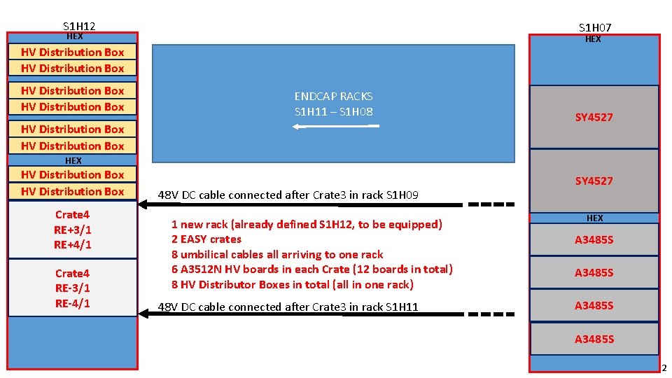
S 1 H 12 S 1 H 07 HEX HV Distribution Box ENDCAP RACKS S 1 H 11 – S 1 H 08 HV Distribution Box SY 4527 HEX HV Distribution Box Crate 4 RE+3/1 RE+4/1 Crate 4 RE-3/1 RE-4/1 48 V DC cable connected after Crate 3 in rack S 1 H 09 1 new rack (already defined S 1 H 12, to be equipped) 2 EASY crates 8 umbilical cables all arriving to one rack 6 A 3512 N HV boards in each Crate (12 boards in total) 8 HV Distributor Boxes in total (all in one rack) 48 V DC cable connected after Crate 3 in rack S 1 H 11 SY 4527 HEX A 3485 S 2
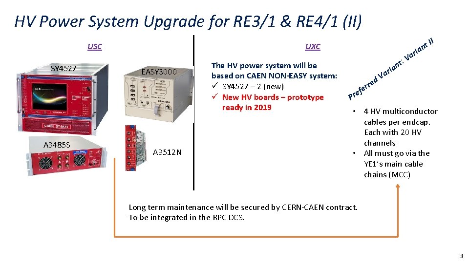
HV Power System Upgrade for RE 3/1 & RE 4/1 (II) USC SY 4527 A 3485 S UXC EASY 3000 A 3512 N The HV power system will be based on CAEN NON-EASY system: ü SY 4527 – 2 (new) ü New HV boards – prototype ready in 2019 r a t: V t ian II n ia ar V d re r e f re P • 4 HV multiconductor cables per endcap. Each with 20 HV channels • All must go via the YE 1’s main cable chains (MCC) Long term maintenance will be secured by CERN-CAEN contract. To be integrated in the RPC DCS. 3
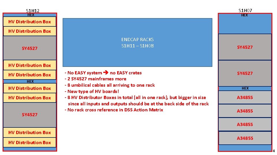
S 1 H 07 S 1 H 12 HEX HV Distribution Box SY 4527 ENDCAP RACKS S 1 H 11 – S 1 H 08 SY 4527 HV Distribution Box HEX HV Distribution Box SY 4527 - No EASY system no EASY crates - 2 SY 4527 mainframes more - 8 umbilical cables all arriving to one rack - New type of HV boards! - 8 HV Distributor Boxes in total (all in one rack), but bigger in size since all inputs and outputs should be at the back side of the rack - No rack cross reference in DSS Action Matrix SY 4527 HEX A 3485 S HV Distribution Box A 3485 S 4
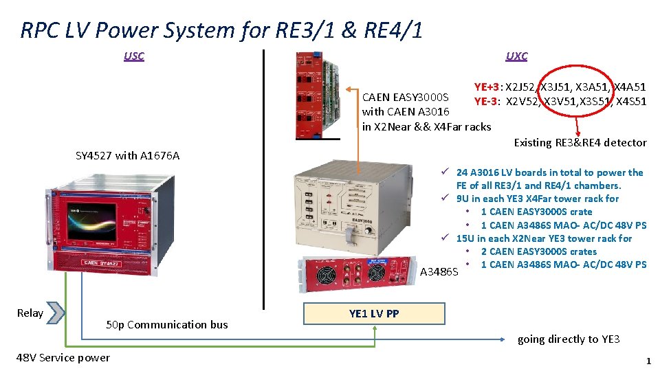
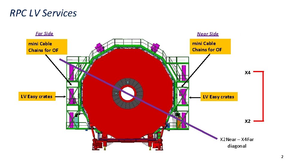
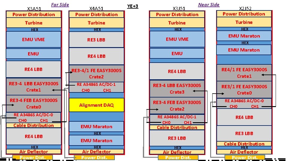
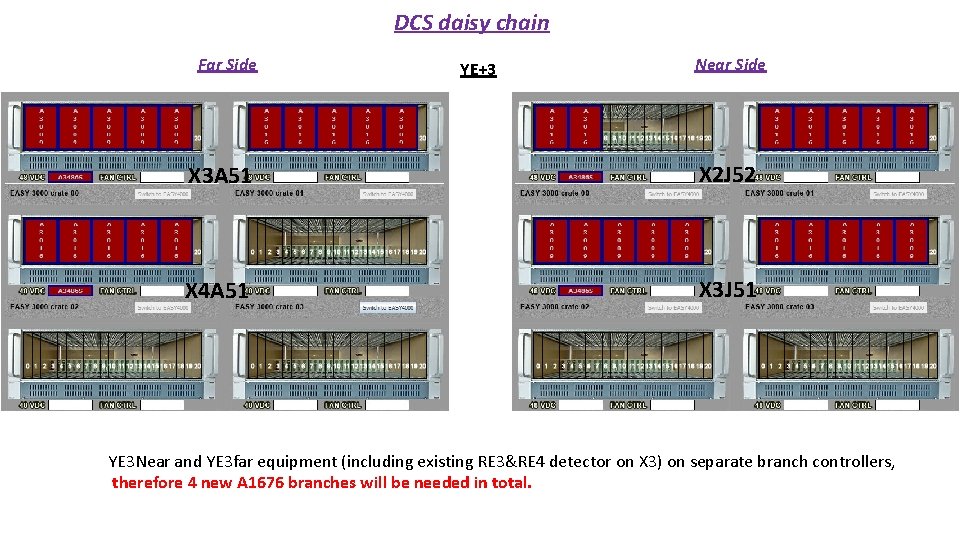
RPC LV Power System for RE 3/1 & RE 4/1 USC UXC YE+3: X 2 J 52, X 3 J 51, X 3 A 51, X 4 A 51 YE-3: X 2 V 52, X 3 V 51, X 3 S 51, X 4 S 51 CAEN EASY 3000 S with CAEN A 3016 in X 2 Near && X 4 Far racks Existing RE 3&RE 4 detector SY 4527 with A 1676 A ü 24 A 3016 LV boards in total to power the FE of all RE 3/1 and RE 4/1 chambers. ü 9 U in each YE 3 X 4 Far tower rack for • 1 CAEN EASY 3000 S crate • 1 CAEN A 3486 S MAO- AC/DC 48 V PS ü 15 U in each X 2 Near YE 3 tower rack for • 2 CAEN EASY 3000 S crates • 1 CAEN A 3486 S MAO- AC/DC 48 V PS A 3486 S Relay 50 p Communication bus 48 V Service power YE 1 LV PP going directly to YE 3 1
RPC LV Services Far Side Near Side mini Cable Chains for OF X 4 LV Easy crates X 2 Near – X 4 Far diagonal 2
Far Side X 3 A 51 Power Distribution X 4 A 51 Power Distribution YE+3 Near Side X 3 J 51 X 2 J 52 Power Distribution Turbine HEX HEX EMU VME RE 3 LBB EMU VME EMU HEX EMU Maraton EMU RE 4 LBB RE 3 -4/1 FE EASY 3000 S Crate 2 RE 4 LBB RE 4/1 FE EASY 3000 S Crate 1 RE 3 -4 LBB EASY 3000 S Crate 1 RE A 3486 S AC/DC-1 CH 0 CH 1 RE 3 -4 LBB EASY 3000 S Crate 3 RE 3/1 FE EASY 3000 S Crate 0 Alignment DAQ RE 3 -4 FEB EASY 3000 S Crate 2 RE A 3486 S AC/DC-0 CH 1 RE A 3486 S AC/DC-1 CH 0 CH 1 RE 4 LBB RE 3 -4 FEB EASY 3000 S Crate 0 RE A 3486 S AC/DC-0 CH 1 Cable Distribution RE 4 LBB HEX Air Deflector Power Dist. EMU Maraton HEX Air Deflector Power Dist. Cable Distribution RE 3 LBB HEX Air Deflector Power Dist. RE 3 LBB Cable Distribution HEX Air Deflector Power Dist.
DCS daisy chain Far Side YE+3 Near Side X 3 A 51 X 2 J 52 X 4 A 51 X 3 J 51 YE 3 Near and YE 3 far equipment (including existing RE 3&RE 4 detector on X 3) on separate branch controllers, therefore 4 new A 1676 branches will be needed in total.
- Slides: 26