Series resistor calculation The formula to calculate the


")

- Slides: 54
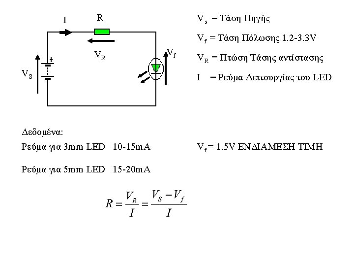
Series resistor calculation The formula to calculate the correct resistance to use is where power supply voltage (Vs) is the voltage of the power supply, e. g. a 9 volt battery, LED voltage drop (Vf) is the forward voltage drop across the LED, and LED current (I) is the desired current of the LED. The above formula requires the current in amperes, although this value is usually given by the manufacturer in milliamperes, such as 20 m. A. Typically, the forward voltage of an LED is about 1. 8– 3. 3 volts; it varies by the color of the LED. A red LED typically drops 1. 8 volts, but voltage drop normally rises as the light frequency increases, so a blue LED may drop around 3. 3 volts. The formula can be explained considering the LED as a resistance, and applying Kirchhoff's voltage law (KVL) (R is the unknown quantity):
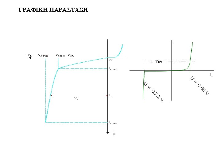
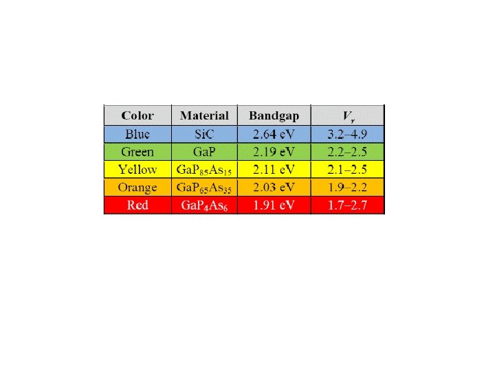
A "Natural" or "Characteristic" voltage develops across a LED when it is correctly connected in a circuit with a current-limiting resistor to allow a current of between 1 m. A and 20 m. A. This voltage is shown in the table above and we normally use the lower value for each colour. However the table shows the voltage varies quite a lot and this depends on the actual crystalline construction of the crystal and the way it is manufactured. You cannot change this and that's why you need to measure the voltage across the LED when building some of the circuits.
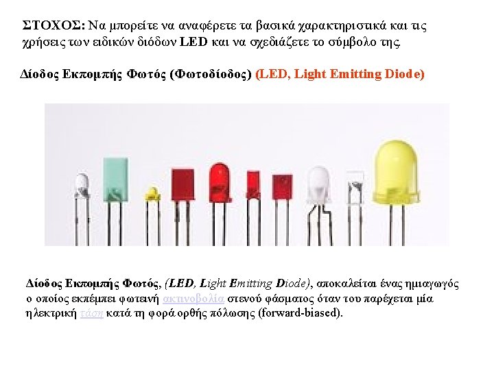
ΕΝΩΝΟΝΤΑΣ ΕΝΑ LED A LED must be connected around the correct way in a circuit and it must have a resistor to limit the current. The LED in the first diagram does not illuminate because a red LED requires 1. 7 v and the cell only supplies 1. 5 v. The LED in the second diagram is damaged because it requires 1. 7 v and the two cells supply 3 v. A resistor is needed to limit the current to about 25 m. A and also the voltage to 1. 7 v, as shown in the third diagram. The fourth diagram is the circuit for layout #3 showing the symbol for the LED, resistor and battery and how the three are connected. The LED in the fifth diagram does not work because it is around the wrong way.
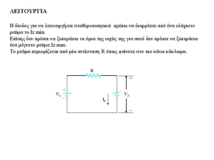
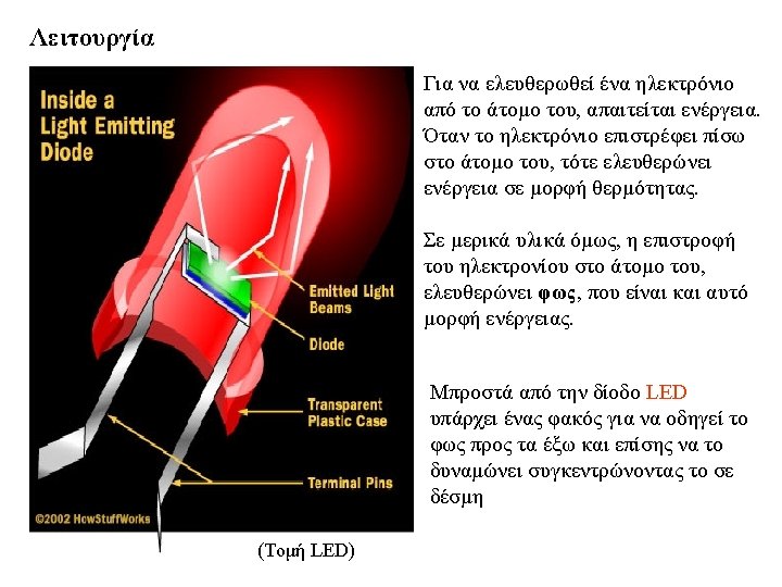
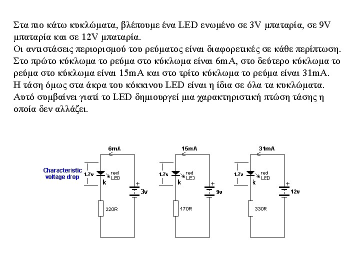
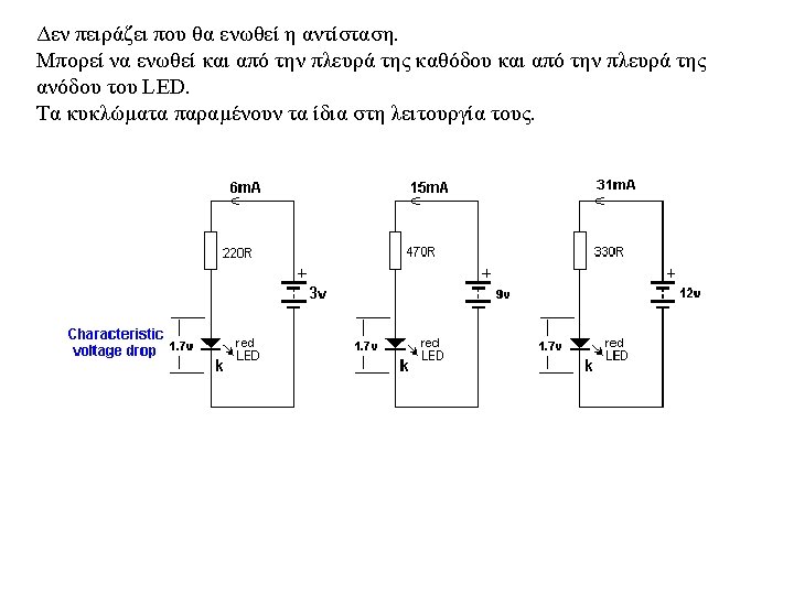
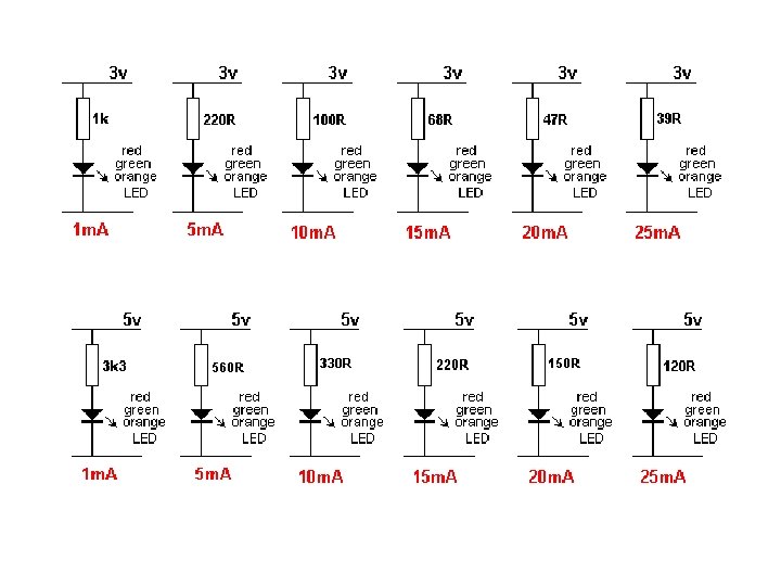
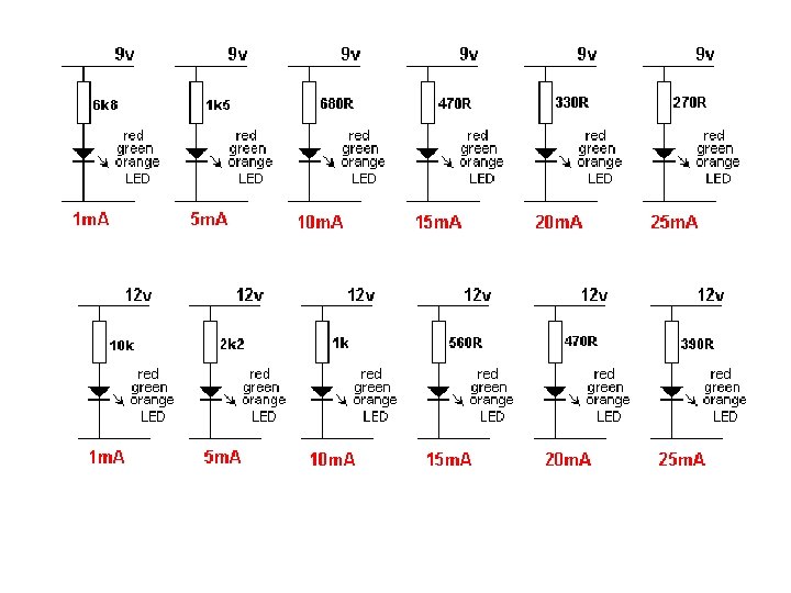
CHARACTERISTIC VOLTAGE DROP When a LED is connected around the correct way in a circuit it develops a voltage across it called the CHARACTERISTIC VOLTAGE DROP. A LED must be supplied with a voltage that is higher than its "CHARACTERISTIC VOLTAGE" via a resistor - called a VOLTAGE DROPPING RESISTOR or CURRENT LIMITING RESISTOR - so the LED will operate correctly and provide at least 10, 000 to 50, 000 hours of illumination. A LED works like this: A LED and resistor are placed in series and connected to a voltage. As the voltage rises from 0 v, nothing happens until the voltage reaches about 1. 7 v. At this voltage a red LED just starts to glow. As the voltage increases, the voltage across the LED remains at 1. 7 v but the current through the LED increases and it gets brighter. We now turn our attention to the current though the LED. As the current increases to 5 m. A, 10 m. A, 15 m. A, 20 m. A the brightness will increase and at 25 m. A, it will be a maximum. Increasing the supply voltage will simply change the colour of the LED slightly but the crystal inside the LED will start to overheat and this will reduce the life considerably. This is just a simple example as each LED has a different CHARACTERISTIC VOLTAGE DROP and a different maximum current.
HEAD VOLTAGE Now we turn our attention to the resistor. As the supply-voltage increases, the voltage across the LED will be constant at 1. 7 v (for a red LED) and the excess voltage will be dropped across the resistor. The supply can be any voltage from 2 v to 12 v or more. In this case, the resistor will drop 0. 3 v to 10. 3 v. This is called HEAD VOLTAGE - or HEAD-ROOM or OVERHEADVOLTAGE. And the resistor is called the CURRENT-LIMIT resistor. The following diagram shows HEAD VOLTAGE: The voltage dropped across this resistor, combined with the current, constitutes wasted energy and should be kept to a minimum, but a small HEAD VOLTAGE is not advisable (such as 0. 5 v). The head voltage should be a minimum of 1. 5 v - and this only applies if the supply is fixed. The head voltage depends on the supply voltage. If the supply is fixed and guaranteed not to increase or fall, the head voltage can be small (1. 5 v minimum). But most supplies are derived from batteries and the voltage will drop as the cells are used.
Here is an example of a problem: Supply voltage: 12 v 7 red LEDs in series = 11. 9 v Dropper resistor = 0. 1 v As soon as the supply drops to 11. 8 v, no LEDs will be illuminated. (Sometimes the LEDs will illuminate because some LEDs will have a characteristic voltage that is slightly less than 1. 7 v and some will illuminate when the voltage is lower than 1. 6 v - but the brightness will reduce considerably. )
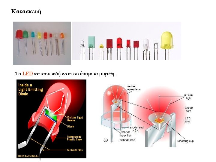
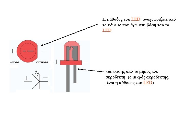
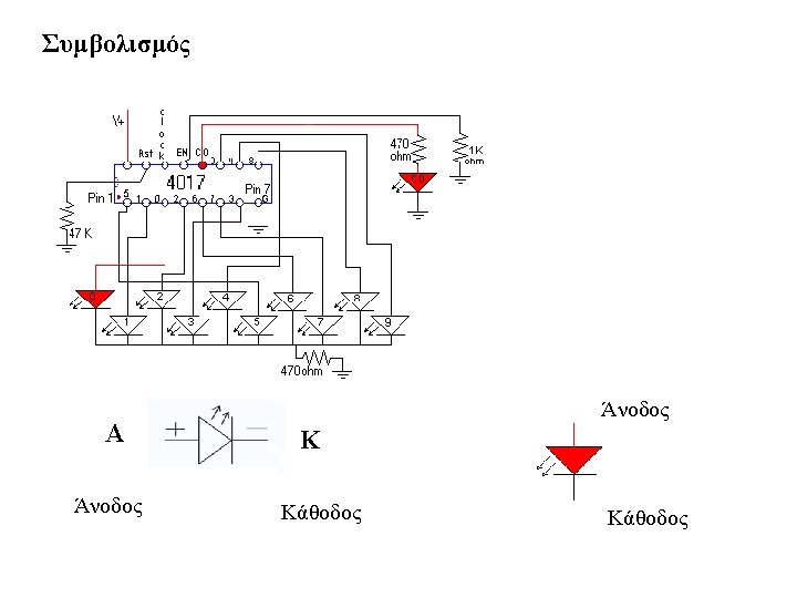
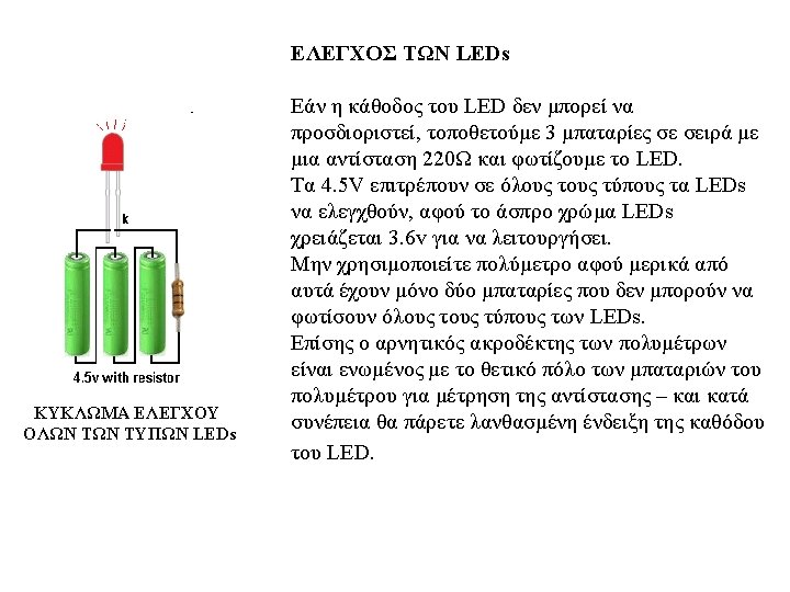
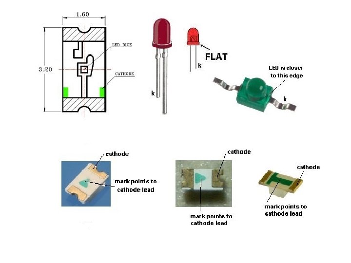
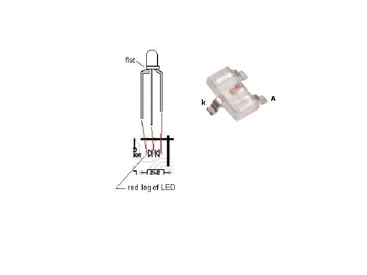
IDENTIFYING A LED does not have a "Positive" or "Negative" lead. It has a lead identified as the "Cathode" or Kathode" or "k". This is identified by a flat on the side of the LED and/or by the shortest lead. This lead goes to the 0 v rail of the circuit or near the 0 v rail (if the LED is connected to other components). Many LEDs have a "flat" on one side and this identifies the cathode. Some surface-mount LEDs have a dot or shape to identify the cathode lead and some have a cut-out on one end. Here are some of the identification marks:
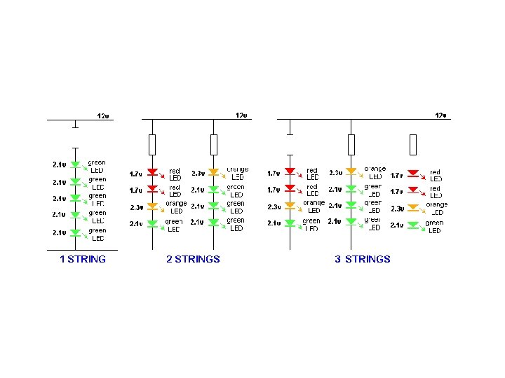
LEDs IN SERIES LEDs can be placed in series providing some features are taken into account. The main item to include is a current-limiting resistor. A LED and resistor is called a string. A string can have 1, 2, 3 or more LEDs. Three things must be observed: 1. MAXIMUM CURRENT through each string = 25 m. A. 2. The CHARACTERISTIC VOLTAGE-DROP must be known so the correct number of LEDs are used in any string. 3. A DROPPER RESISTOR must be included for each string. The following diagrams show examples of 1 -string, 2 -strings and 3 -strings:
LEDs IN PARALLEL LEDs CANNOT be placed in parallel - until you read this: LEDs "generate" or "possess" or "create" a voltage across them called the CHARACTERISTIC VOLTAGE-DROP (when they are correctly placed in a circuit). This voltage is generated by the type of crystal and is different for each colour as well as the "quality" of the LED (such as high-bright, ultra high-bright etc). This characteristic cannot be altered BUT it does change a very small amount from one LED to another in the same batch. And it does increase slightly as the current increases. For instance, it will be different by as much as 0. 2 v for red LEDs and 0. 4 v for white LEDs from the same batch and will increase by as much as 0. 5 v when the current is increased from a minimum to maximum. You can test 100 white LEDs @15 m. A and measure the CHARACTERISTIC VOLTAGE-DROP to see this range.
If you get 2 LEDs with identical CHARACTERISTIC VOLTAGE-DROP, and place them in parallel, they will each take the same current. This means 30 m. A through the current-limiting resistor will be divided into 15 m. A for each LED. However if one LED has a higher CHARACTERISTIC VOLTAGE-DROP, it will take less current and the other LED will take considerably more. Thus you have no way to determine the "current-sharing" in a string of parallel LEDs. If you put 3 or more LEDs in parallel, one LED will start to take more current and will over-heat and you will get very-rapid LED failure. As one LED fails, the others will take more current and the rest of the LEDs will start to self-destruct. The reason why they take more current is this: the current-limit resistor will have been designed so that say 60 m. A will flow when 3 LEDs are in parallel. When one LED fails, the remaining LEDs will take 30 m. A each.
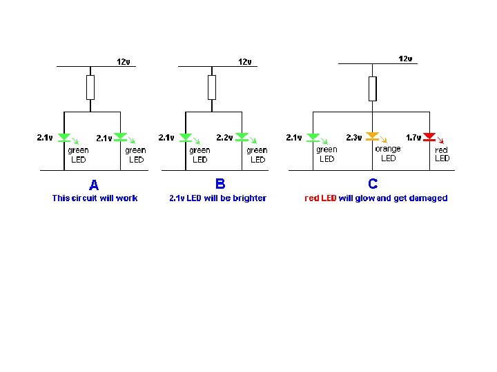
Thus LEDs in PARALLEL should be avoided. Diagram A below shows two green LEDs in parallel. This will work provided the Characteristic Voltage Drop across each LED is the same. In diagram B the Characteristic Voltage Drop is slightly different for the second LED and the first green LED will glow brighter. In diagram C the three LEDs have different Characteristic Voltage Drops and the red LED will glow very bright while the other two LEDs will not illuminate. All the current will pass through the red LED and it will be damaged. The reason why the red LED will glow very bright is this: It has the lowest Characteristic Voltage Drop and it will create a 1. 7 v for the three LEDs. The green and orange LEDs will not illuminate at this voltage and thus all the current from the dropper resistor will flow in the red LED and it will be destroyed.
THE RESISTOR The value of the current limiting resistor can be worked out by Ohms Law. Here are the 3 steps: 1. Add up the voltages of all the LEDs in a string. e. g: 2. 1 v + 2. 3 v + 1. 7 v = 8. 4 v 2. Subtract the LED voltages from the supply voltage. e. g: 12 v - 8. 4 v = 3. 6 v 3. Divide the 3. 6 v (or your voltage) by the current through the string. for 25 m. A: 3. 6/. 025 =144 ohms for 20 m. A: 3. 6/. 02 = 180 ohms for 15 m. A: 3. 6/. 015 = 250 ohms for 10 m. A: 3. 6/. 01 = 360 ohms This is the value of the current-limiting resistor.
http: //www. talkingelectronics. com/projects/30%20 LED%20 Projects. html
Simple LED circuit with 9 V battery (5 mm or T 1 3/4 sizes are most popular). Series LED circuit (Source Voltage – LED Voltage Drop) / Amps = OHMs Amps = m. A/1000 Example: Source Voltage = 9 volts Voltage Drop = 3. 1 volts typical for a blue or white LED Desired Current = 13 milliamps So the resistor we need is: (9 – 3. 1) / ( 13 / 1000 ) = 452 ohms so we will use a 470 Ω resistor.
Most LEDs will burn out if connected to a 9 V battery without a resistor. The resistor lowers the amount of current flowing through the LED. To calculate how much resistance is needed, you can assume the average LED takes around 2 V and 20 m. A (if you want to be more precise, look up by color, or to be exact, look at the LED’s datasheet). Resistor values +-20% usually fine, but calculate exactly to get the most brightness without losing efficiency. If you wire more LEDs in series, or you use white or blue LEDs which require more power, you will need a lower resistor:
Making an LED Flickering Candle A blinking LED includes a tiny integrated circuit (IC) built into the LED itself. Most blinking LEDs operate from 3. 5 V to 9 V, but you should ask the seller or manufacturer to be sure. Blinking LEDs are available in various colors, although red is most common. Expect to pay around $0. 60 each per ultra bright flashing LED.
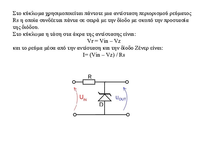
220 volt LED circuit We use one capacitor, a zener diode, a resistor and the LED. The capacitors value depend on LED current. With a 100 n. F capacitor, the LED current is 4 m. A; at 470 n. F the current is 20 m. A.