Series and Parallel A C Circuits Electrical Engineering
 Mechanical Engineering/ first class College")


 as being equal to 1/Z. The")


- Slides: 18
Series and Parallel A. C. Circuits Electrical Engineering (2) Mechanical Engineering/ first class College of Engineering University of Al-Qadisiya Lecturer: Yousif M. H.
OBJECTIVES Become familiar with the characteristics of series and parallel ac networks and be able to find current, voltage, and power for each element. Be able to find the total impedance of any series or parallel ac network and sketch the impedance and admittance diagram of each. Applying KVL and KCL to any series or parallel configuration. Be able to apply the VDR or CDR to any ac network.
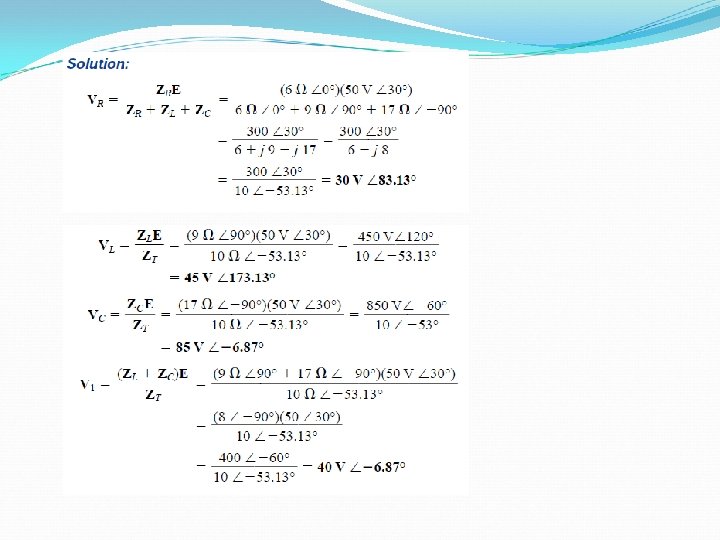
VOLTAGE DIVIDER RULE EXAMPLE: Using the voltage divider rule, find the unknown voltages VR, VL, VC, and V 1 for the circuit of Fig.
ADMITTANCE In ac circuits, we define admittance (Y) as being equal to 1/Z. The unit of measure for admittance as defined by the SI system is Siemens, which has the symbol S. FIG. 15. 58 Parallel ac network.
ADMITTANCE DIAGRAM FIG. Admittance diagram.
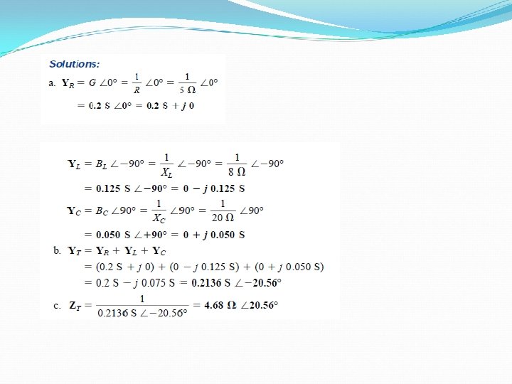
ADMITTANCE EXAMPLE: For the network of Fig. : a. Find the admittance of each parallel branch. b. Determine the input admittance. c. Calculate the input impedance. d. Draw the admittance diagram. FIG. Impedance diagram for the network FIG. Admittance diagram for the network
PARALLEL ac NETWORKS FIG. Parallel ac network.
PARALLEL ac NETWORKS R-L-C FIG. Parallel R-L-C ac network. FIG. Applying phasor notation to the network.
PARALLEL ac NETWORKS R-L-C FIG. Admittance diagram for the parallel R-L-C network in Fig.
PARALLEL ac NETWORKS R-L-C FIG. Phasor diagram for the parallel R-L-C network in Fig.
PARALLEL ac NETWORKS R-L-C FIG. Waveforms for the parallel R-L-C network in Fig. .
CURRENT DIVIDER RULE Applying the current divider rule. EXAMPLE : Using the current divider rule, find the current through each impedance of Fig.
CURRENT DIVIDER RULE EXAMPLE: Using the current divider rule, find the current through each parallel branch of Fig.
EQUIVALENT CIRCUITS
EQUIVALENT CIRCUITS FIG. Finding the series equivalent circuit for a parallel R-L network.
EQUIVALENT CIRCUITS EXAMPLE : Determine the series equivalent circuit for the network of Fig. FIG. Example 15. 18. FIG. The equivalent series circuit for the parallel network in Fig.