
Senior Design I Project P 08454 Anthony Squaire



- Slides: 16
Senior Design I Project – P 08454 Anthony Squaire – Team Leader - Industrial and Systems Engineering Alan Mattice – Lead Engineer - Mechanical Engineer Cody Ture - Mechanical Engineer Brian Bullen – Mechanical Engineer Charles Trumble – Mechanical Engineer Aron Khan – Electrical Engineer Jeff Cowan – Electrical Engineer Andre Mc Rucker – Computer Engineer
BLWRPG 17 Brushless DC Motor • Planetary Gear Ratio: 4. 9 to 1 • Torque: • 24. 07 oz-in @4200 rpm (Un-geared) • 117. 943 oz-in @857 rpm (Geared) • Power: 25 W • Weight: 1. 37 lbs Figure 1: Motor Picture from Anaheim Automation • Dimensions: 2. 36 in (Motor), 1. 39 in (Gearbox), 1. 654 in (Diameter) Figure 2: Motor dimensions from Anaheim Automation
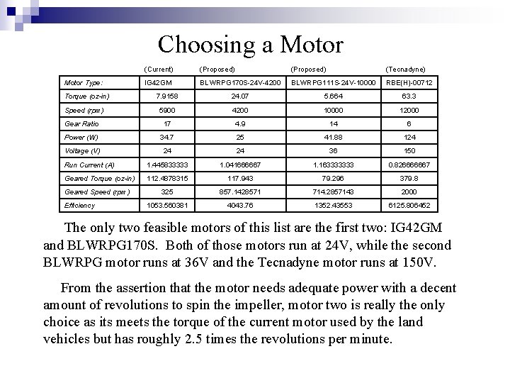
Choosing a Motor (Current) (Proposed) (Tecnadyne) IG 42 GM BLWRPG 170 S-24 V-4200 BLWRPG 111 S-24 V-10000 RBE(H)-00712 7. 9158 24. 07 5. 664 63. 3 5900 4200 10000 12000 Gear Ratio 17 4. 9 14 6 Power (W) 34. 7 25 41. 88 124 Voltage (V) 24 24 36 150 Run Current (A) 1. 445833333 1. 041666667 1. 163333333 0. 826666667 Geared Torque (oz-in) 112. 4878315 117. 943 79. 296 379. 8 325 857. 1428571 714. 2857143 2000 1053. 560381 4043. 76 1352. 43553 6125. 806452 Motor Type: Torque (oz-in) Speed (rpm) Geared Speed (rpm) Efficiency The only two feasible motors of this list are the first two: IG 42 GM and BLWRPG 170 S. Both of those motors run at 24 V, while the second BLWRPG motor runs at 36 V and the Tecnadyne motor runs at 150 V. From the assertion that the motor needs adequate power with a decent amount of revolutions to spin the impeller, motor two is really the only choice as its meets the torque of the current motor used by the land vehicles but has roughly 2. 5 times the revolutions per minute.
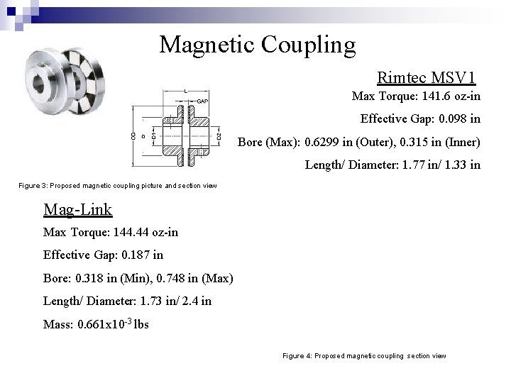
Magnetic Coupling Rimtec MSV 1 Max Torque: 141. 6 oz-in Effective Gap: 0. 098 in Bore (Max): 0. 6299 in (Outer), 0. 315 in (Inner) Length/ Diameter: 1. 77 in/ 1. 33 in Figure 3: Proposed magnetic coupling picture and section view Mag-Link Max Torque: 144. 44 oz-in Effective Gap: 0. 187 in Bore: 0. 318 in (Min), 0. 748 in (Max) Length/ Diameter: 1. 73 in/ 2. 4 in Mass: 0. 661 x 10 -3 lbs Figure 4: Proposed magnetic coupling section view
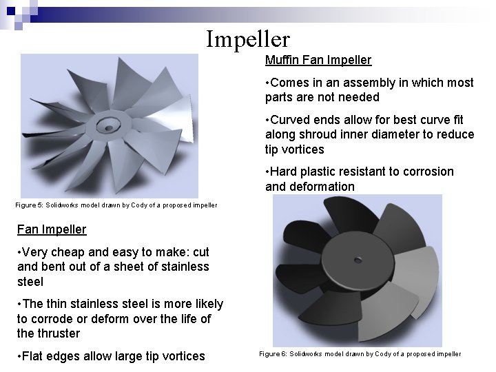
Impeller Muffin Fan Impeller • Comes in an assembly in which most parts are not needed • Curved ends allow for best curve fit along shroud inner diameter to reduce tip vortices • Hard plastic resistant to corrosion and deformation Figure 5: Solidworks model drawn by Cody of a proposed impeller Fan Impeller • Very cheap and easy to make: cut and bent out of a sheet of stainless steel • The thin stainless steel is more likely to corrode or deform over the life of the thruster • Flat edges allow large tip vortices Figure 6: Solidworks model drawn by Cody of a proposed impeller
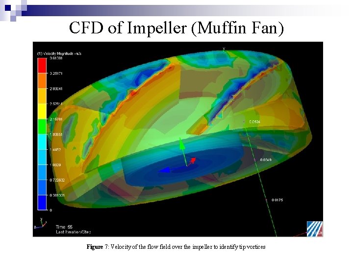
CFD of Impeller (Muffin Fan) Figure 7: Velocity of the flow field over the impeller to identify tip vortices
CFD of Impeller (Muffin Fan)cont… Figure 8: Velocity of the flow perpendicular to the axis of rotation
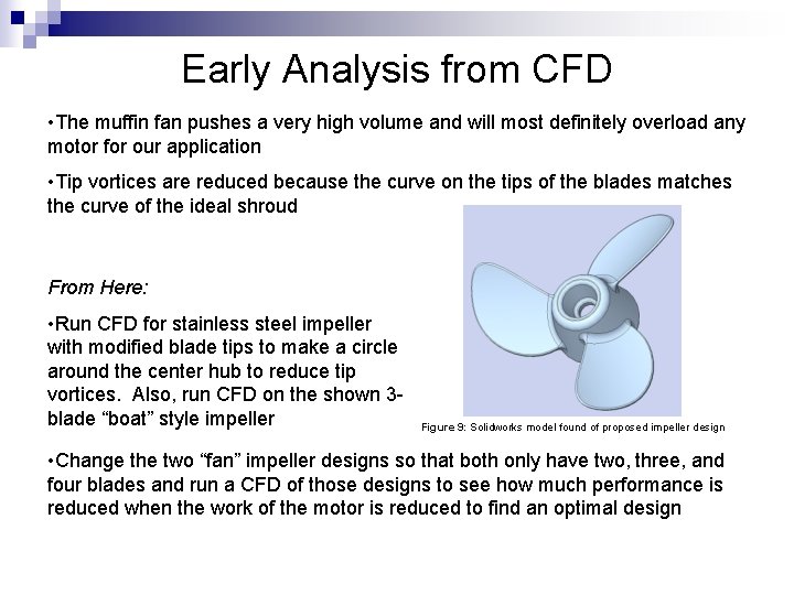
Early Analysis from CFD • The muffin fan pushes a very high volume and will most definitely overload any motor for our application • Tip vortices are reduced because the curve on the tips of the blades matches the curve of the ideal shroud From Here: • Run CFD for stainless steel impeller with modified blade tips to make a circle around the center hub to reduce tip vortices. Also, run CFD on the shown 3 blade “boat” style impeller Figure 9: Solidworks model found of proposed impeller design • Change the two “fan” impeller designs so that both only have two, three, and four blades and run a CFD of those designs to see how much performance is reduced when the work of the motor is reduced to find an optimal design
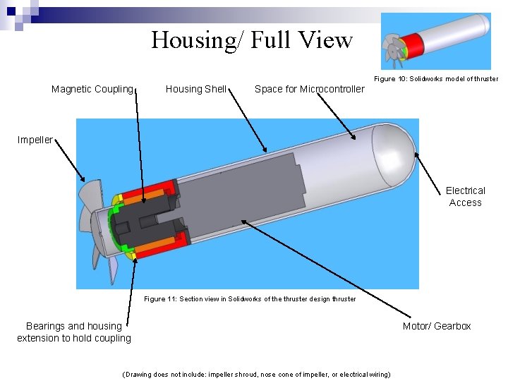
Housing/ Full View Figure 10: Solidworks model of thruster Magnetic Coupling Housing Shell Space for Microcontroller Impeller Electrical Access Figure 11: Section view in Solidworks of the thruster design thruster Bearings and housing extension to hold coupling (Drawing does not include: impeller shroud, nose cone of impeller, or electrical wiring) Motor/ Gearbox
Thermal and Magnetic Concerns Thermal • The motor, microcontroller, and H-bridge will generate heat that needs to be dissipated out into the surroundings. • May need to use a dissipative fluid (oil) or large heat sink to help remove this heat as the most sensitive component ( microcontroller) needs a temperature less than 194 o. F (90 o. C) • Downside to oil: need to seal off compartment for microcontroller • Downside to heat sink: takes up space in housing Magnetic Shielding • May need to block strong magnetic field generated by the motor to protect the microcontrollers circuitry • Need a partition or separate compartment for the microcontroller Needs: • Using the heat generated from the motor and the microcontroller, a heat transfer analysis needs to be completed to see if a convective fluid is needed to better dissipate the heat so that the motor and microcontroller will operate within acceptable temperature parameters • Determine if the magnetic field of the motor is strong enough to affect the circuitry of the microcontroller • If it is, design a barrier or contained space in which the microcontroller can function without being affected by the magnetic field
3 -Phase Brushless DC Motor Driver Figure 12: ST Microelectronics L 6235 motor driver
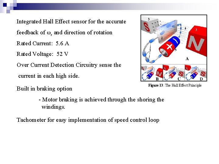
Integrated Hall Effect sensor for the accurate feedback of ωr and direction of rotation Rated Current: 5. 6 A Rated Voltage: 52 V Over Current Detection Circuitry sense the current in each high side. Built in braking option Figure 13: The Hall Effect Principle - Motor braking is achieved through the shoring the windings. Tachometer for easy implementation of speed control loop
FPGA vs. Microcontroller
Microcontroller Pugh Matrix
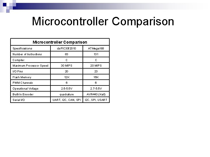
Microcontroller Comparison Specifications ds. PIC 30 f 2010 ATMega 168 Number of Instructions 83 131 Compiler C C 30 MIPS 20 23 12 K 16 K 6 6 2. 5 -5. 5 V 2. 7 -5. 5 V quadrature AVR 443 (Hall) UART, I 2 C, CAN, SPI I 2 C, SPI, USART Maximum Processor Speed I/O Pins Flash Memory PWM Channels Operational Voltage Built-In Encoder Serial I/O
Figure Sources n n n n Figure 1: Anaheim Automation: http: //anaheimautomation. com/blwrpg 17_brushless_dc_planetary_gearmotors. aspx Figure 2: Anaheim Automation: http: //anaheimautomation. com/blwrpg 17_brushless_dc_planetary_gearmotors. aspx Figure 3: Huco Dynatork: http: //www. huco. com/products. asp? p=true&cat=506 Figure 4: Rimtec Corporation: http: //www. rimteccorporation. com/products/magnetic/pdf/msv. pdf Figure 9: 3 D Content Central: http: //www. 3 dcontentcentral. com/3 DContent. Central/Download. Model. aspx? catalogid=171&id=517 Figure 12: ST Microelectronics: http: //www. st. com/stonline/products/literature/an/9214. pdf Figure 13: Wikipedia: http: //en. wikipedia. org/wiki/Hall_effect Information Sources n n n n Anaheim Automation: http: //www. anaheimautomation. com Shayang Ye: http: //www. allproducts. com/ee/shayye/ Danaher Motion: http: //kmtg. kollmorgen. com/products/motors/ Huco Dynatork: http: //www. huco. com Rimtec Corporation: http: //www. rimteccorporation. com ST Microelectronics: http: //www. st. com Microchip: http: //www. microchip. com Atmel Corporation: http: //www. atmel. com