SENG 5130 SYSTEMS ENGINEERING PROCESSES MODULE 13 MODEL

 Practical Guide to Sys. ML: The Systems")


 interacting with the automobile Define system boundary for clear")


")

")

")

 (Drive Represents behavior in terms of a sequence of messages")
 Represents behavior in terms of a sequence of messages")


- Slides: 24
SENG 5130 SYSTEMS ENGINEERING PROCESSES MODULE 13 MODEL BASED SYSTEMS ENGINEERING PART 3
References • • Friedenthal, Moore, Steiner (2009) Practical Guide to Sys. ML: The Systems Modeling Language Tim Weilkiens (2006) Systems Engineering with Sys. ML/UML: Modeling, Analysis, Design Friedenthal, Wolfrom (2010) Modeling with Sys. ML, INCOSE Symposium Friedenthal, Moore, Steiner (2009) OMG Systems Modeling Language Tutorial,
MODULE 13 Model Based Systems Engineering Part 3
Automobile Example
Systems Engineering Process 1. 2. 3. 4. 5. Example: Automobile Design What are the steps? Identify Stakeholders Analyze Needs System Requirements Functional Requirements System Design
1. Identify Stakeholders Buyer Users � Driver � Passenger Market Segment � Family car vs sports car vs utility vehicle Manufacturers Maintenance Governments (laws and regulations)
2. Analyze Needs Understand needs of each stakeholder Define measures of effectiveness with target values Target values � Bound solution space � Evaluate alternatives � Aesthetics � Performance � Fuel economy � Safety � Reliability � Repair time
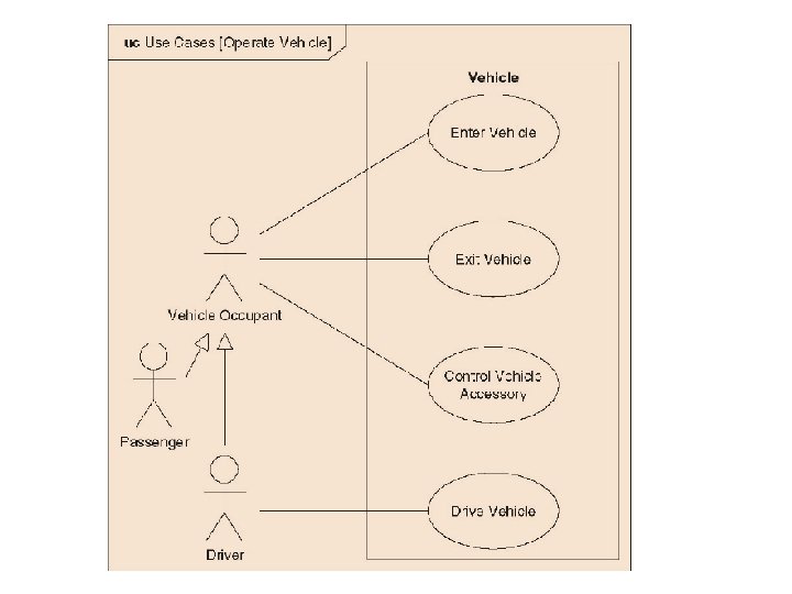
3. System Requirements External system(s) interacting with the automobile Define system boundary for clear interfaces External user(s) interacting with the automobile Physical environment interacting with the automobile
4. Functional Requirements What the system must do to address goals � Accelerating � Breaking � Steering Inputs and Outputs for each function Sequence and order of the functions Required level of performance � “The automobile is required to accelerate from 0 to 60 mph in less than 8 seconds under specified conditions. ” � Physical characteristics (max. vehicle weight, etc. )
5. System Design Identify system components and specific component requirements System physical components: � Engine � Transmission � Chassis � Body � Breaks � Etc.
How do we model the automobile using Sys. ML? Venomgt. com
2. Requirements Diagram (Traceability)
4. Block Definition Diagram Represents structural elements called blocks, and their composition and classification
4. Block Definition Diagram (Vehicle System Hierarchy)
5. Internal Block Diagram Represents interconnection and interfaces between the parts of a block
5. Internal Block Diagram (Power Subsystem)
6. Activity Diagram Represents behavior in terms of the ordering of actions based on the availability of inputs, outputs, and control, and how the actions transform the inputs to outputs
7. Sequence Diagram Vehicle) (Drive Represents behavior in terms of a sequence of messages exchanged between parts
7. Sequence Diagram (Start Vehicle) Represents behavior in terms of a sequence of messages exchanged between parts
8. State Machine Diagram Represents behavior of an entity in terms of its transitions between states triggered by events
9. Parametric Diagram Represents constraints on property values, such as F=m*a, used to support engineering analysis
Class Exercise 1. 2. 3. Choose one part of your Final Project System Model it using Sys. ML in Visio 1. Use Case Diagram 2. Activity Diagram 3. Sequence Diagram 4. State Machine Diagram E-mail me the diagrams, and add them to your project.
Questions? Comments?