Selective Laser Sintering By Rohan Malkar 132090008 Swapnil
 Swapnil Pawar(132090006)")
Selective Laser Sintering By Rohan Malkar (132090008) Swapnil Pawar(132090006)
 can be defined as a group")
Definition of Rapid prototyping • Rapid Prototyping (RP) can be defined as a group of techniques used to quickly fabricate a scale model of a part or assembly using three-dimensional computer aided design (CAD) data.

Why Rapid Prototyping The reasons of Rapid Prototyping are • To increase effective communication. • To decrease development time. • To decrease costly mistakes. • To minimize sustaining engineering changes. • To extend product lifetime by adding necessary features and eliminating redundant features early in the design.

Rapid Prototyping • Goal is to fabricate 3 -D models quickly and automatically directly from CAD models. • Current RP system are based on Layered Manufacturing Technology. • In this method solid model ( triangle polyhedral form ) is decomposed into cross sectional layer representation. • The RP software prepares tool path to physically built these layers automatically to form the object in the machine.

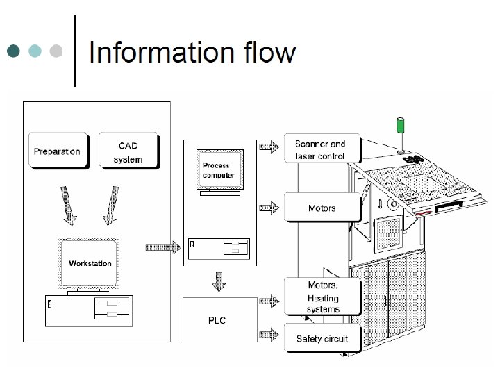
RP process chain showing fundamental process steps

• Depending upon the form of the raw materials used RP systems are classified as follows: RP Systems Liquid based processes LOM SLA Liquid Solid based processes Solid FDM SGC SLS Powder

Selective Laser Sintering • Selective laser sintering was originally developed by University of Texas at Austin. • Commercialised by DTM Corporation USA. DTM’S SLS is presently owned by 3 D systems. • It is a solid based RP process. • It is the first process to emerge at the commercial scale to make metallic parts and tools. • Selective Laser Sintering (SLS) uses a laser to sinter powder based materials together, layer-by-layer, to form a solid model.

A SLS system has three major components: SLS system Laser Part Chamber Build Platform Levelling Roller Power cartridge Control System

Schematic of SLS apparatus

Methodology 1 • CAD Model 2 • Conversion to STL format 3 • Slicing model into layers (RP software). 4 • Development of Laser Trajectory. 5 • Building of Model in the Machine

Step 1 Step 3 Step 2 Step 4
")
Step 5 Metal Powder SLS Machine ( Courtesy EOS )

Working of SLS • It is an additive RP techniques. • Layer of powder is first deposited on part build cylinders. • The laser ( CO 2 ) traces a two-dimensional cross section of the part. • During laser exposure, the powder temperature rises above the glass transition point after which adjacent particles flow together. This process is called sintering. • Platform descends down by an amount equal to the thickness. • The roller pushes the material on the built platform and the process is repeated again an again.

• Following video will clearly depict the working of the sls process.

Materials used for SLS. • Metallic and non metallic powders are used typically of the size 50µm. • Commonly used materials: 1. Plastics 2. Waxes (Investment wax casting) 3. Low melting temperature metal alloys. 4. Polymer coated metals. 5. Ceramics (Green preforms). 6. Nylon ( Duraform, Glass-Filled Nylon (Duraform GF), Flame Retardant Nylon and Durable Nylon. )

SLS Products Engine Manifold Valve Medical implant Electronic Packaging

Complexity!!! Not a Problem…In SLS

Strengths of SLS • Any material that can be converted into powder having low melting temperature (350 to 500) can be used to make parts in this process. • No support structure required. • Parts obtained are tough. • No post curing required. • No tooling cost incurred. • No wastage of material. • Functional metal and ceramic parts can be obtained directly.

Weakness of SLS • Surface finish is improper. • Parts are porous in nature. • Continuous monitoring of the building operation is required. • Large amount of time is required to heat up material chamber before building part. • Uniform cooling is difficult to maintain in order to avoid warpage. • Parts obtained are brittle.
 Selective Lasser Sintering (SLS) • Limited to photosensitive resins making it brittle.")
Steriolithoraphy (SLA) Selective Lasser Sintering (SLS) • Limited to photosensitive resins making it brittle. • Polymers can be used for sintering thereby approximating thermoplastics. • Surface finish operation as required since part is powdery. • Good surface finish • Accuracy is very high. • Less prone to residual stresses. • SLA suffers from trapped volume problem (cups in the structure which hold hot fluid cause inaccuracies) • Accuracy is one of the biggest disadvantage of this process. • Higher residual stresses due to longer curing. • SLS does not have this problem.

SLA • SLA products are difficult to machine due to their brittle nature. SLS • SLS and SLA objects can be made of the same size. • SLA is rarely preferred ( “ Quick cast” is the one process in which investment casting is preferred developed by 3 D systems using SLA. ) • SLS is mostly used in investment casting also sometimes to prepare master patterns. • SLS product are made from thermoplastic material which can be easily machined.

Areas employing SLS • • • Aerospace. Automotive. Organ replacement. Haemotology. Surgical Tools. Medical Instruments.
- Slides: 23