SECTIONAL VIEWS AND CONVENTIONS 1 PURPOSE OF SECTIONAL


 Visible Edges shown (Recommended) Visible Edges not shown")


- Slides: 19
SECTIONAL VIEWS AND CONVENTIONS 1. PURPOSE OF SECTIONAL VIEWS • To see the inner details of an object. • Sectional views help in clarifying the interior shape of a part because in the outer view too many hidden lines can create confusion. • To sometimes see small cross sections of a part.
Hidden Lines in the Front View create confusion in the understanding of the shape of part.
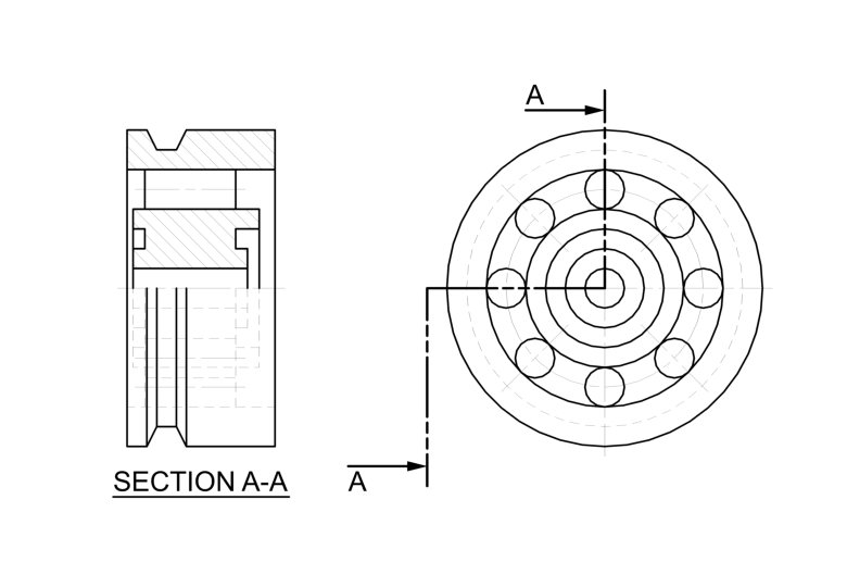
The sectioned Front View clearly shows the internal part shape. SECTION A-A
2. HOW SECTIONS ARE SHOWN • The place from which the section is taken shall be clearly identified. • A cutting plane, directional arrows and identification letters shall be used. • A sectional view must show which portions of the object are solid material and which are spaces by drawing section lines in the solid parts.
3. TYPES OF SECTIONS A. Full Section • The cutting plane shall pass entirely through the solid. • The cutting plane may cut straight across or change direction to pass through features to be shown.
A full section with the cutting plane passing straight across.
A full section with the cutting plane changing direction • Change in plane direction shall never be shown in the sectioned view.
B. Half Section • The cutting plane passes through one half of the solid. • Used for symmetrical solids. • One half of the solid is sectioned while the other half is the regular exterior view. • Advantageous in the fact that both interior and exterior can be shown without drawing hidden lines. • Difficult in dimensioning
• In a half section, hidden lines are usually not shown in the exterior half. • The two halves in the sectioned view are separated by a center line.
C. Broken-Out Section • To be used where an interior portion must be shown but a full or half section cannot be used because the cutting plane would remove some feature that must included. • An irregular break line is used to limit the extent of the section.
D. Rotated Section • Used for showing cross sections of parts while saving space. • Section is drawn on the view by rotating the section at 90 o.
E. Removed Section • Used for the same purpose as rotated section but the section is removed and placed adjacent to the drawing of the part. • The cutting plane with reference letters shall be mentioned.
F. Auxiliary Section • Conforms to the principles of orthographic projections. • Used to show section of an inclined feature. • All types of section, i. e. , full, half, broken out, rotated and removed are used.
4. DRAWING PRACTICES FOR SECTIONAL VIEWS A. Unnecessary Hidden Detail • Hidden edges and surfaces are not shown behind the cutting plane. B. Visible Detail • Visible edges and surfaces shall be shown behind the cutting plane. • Shall be omitted only if the section is to be emphasized on.
Visible Edges not shown (Not recommended) Visible Edges shown (Recommended) Visible Edges not shown (Recommended)
C. Section Lining • A pattern of lines shall be used to fill the areas of the solid material cut by the section plane. • Usually at 45 o to part’s principal surfaces, but other angles such as 15 o, 30 o, 60 o and 75 o can also be used. • Section lines shall be thin and fine lines and shall be equally spaced. • Direction and/or spacing of section lines shall be changed for adjacent parts. • Various patterns are sometimes used for different materials.
5. PARTS NOT SECTIONED • Parts that are more easily recognized by their exterior are not sectioned. • Bolts, nuts, screws, studs, pins, keys, cotters, rivets etc. are all fasteners and therefore shall not be sectioned. Shafts shall also not be sectioned unless inner details are required.