Section II Applications of Measurements 2 Earthwork Profile


 ﻣﺆﺨﺮﺓ BM 09 1. 573 Intermediate sight (IS) ﻣﺘﻮﺳﻄﺔ 1.")
 ﻣﺆﺨﺮﺓ BM 09 1. 573 Intermediate sight (IS) ﻣﺘﻮﺳﻄﺔ 1.")


- Slides: 14
Section II Applications of Measurements 2. Earthwork ﻛﻤﻴﺎﺕ ﺍﻟﺤﻔﺮ ﻭ ﺍﻟﺮﺩﻡ
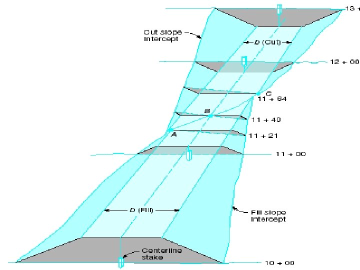
Profile Leveling ﺍﻟﻘﻄﺎﻋﺎﺕ ﺍﻟﻄﻮﻟﻴﺔ • To collect data about topography along a reference line. • Mainly to compute volumes of cut and fill ﺍﻟﺤﻔﺮ ﻭ ﺍﻟﺮﺩﻡ for a proposed linear structure, such as: highways, railroads, transmission lines, canals. Then the best route can be chosen. • The result: elevations at definite points (stations) along a reference line, usually the center line.
Field Procedures Profile leveling
• First a backsight at a BM is observed. • Then, a number of intermediate sights are observed at the locations needed, do not have to be at equal distances. • When the distance becomes too long, or readings become hard to observe, a turning point ﻧﻘﻄﺔ ﺩﻭﺭﺍ ﻥ is constructed. • You cannot keep the backsight distance equal to the foresight distance. • Elevation computation: – – Elevation of line of sight (LS) = EBM + BSBM. Elevation of any intermediate point = ELS - ISIP. Elevation of point at FS = ELS - FSPOINT Handle new level positions as in differential leveling, construct a turning point and knowing BS and FS readings, compute a new elevation of line of sight.
Example Point Backsight (BS) ﻣﺆﺨﺮﺓ BM 09 1. 573 Intermediate sight (IS) ﻣﺘﻮﺳﻄﺔ 1. 472 2 1. 718 1. 352 4 5 6 Elevation of line of sight (HI) ﻣﻨﺴﻮﺏ ﺧﻂ ﺍﻟﻨﻈﺮ Elevation 20. 00 1 3 Foresight (FS) ﻣﻘﺪﻣﺔ 1. 551 1. 181 1. 492 1. 212 2. 101
Answer Point Backsight (BS) ﻣﺆﺨﺮﺓ BM 09 1. 573 Intermediate sight (IS) ﻣﺘﻮﺳﻄﺔ 1. 472 2 1. 718 1. 352 4 5 Elevation of line of sight (HI) ﻣﻨﺴﻮﺏ ﺧﻂ ﺍﻟﻨﻈﺮ 21. 573 1 3 Foresight (FS) ﻣﻘﺪﻣﺔ 20. 00 20. 101 19. 885 1. 551 21. 374 1. 181 1. 212 Elevation 20. 022 20. 193 1. 492 6 2. 101 21. 094 19. 882 18. 993
Drawing and Using Profiles • Drawn using a software now. • To manually draw a profile and compute earthwork: – Assume the horizontal axis is the distance and the vertical axis is the elevation. – Use a larger scale for the elevation than the scale of the distance, usually 10 times larger. – Draw the design line at the proposed grade ﺍﻟﻤﻴﻞ. – Compute the areas of cut and fill. – Multiply area by width to get volumes. – Gradient ( ﺍﻟﻤﻴﻞ percent grade) is the rise or fall in m per 100.
1 m 10 m Horizontal scale 1: 2500 Vertical scale 1: 250
Example The table below shows ground elevations along the centerline of a proposed pipeline. If the bottom of the trench to be excavated is at elevation (+115 m) at point (A) and slopes -1%, and the trench is 2 m wide, compute the volumes of cut and fill. {Answer is given in lecture} Point Distance (m) Elevation (m) A 0. 0 115. 0 B 100 117. 2 C 200 116. 0 D 300 112. 0 E 400 110. 5 F 500 110. 0
Borrow-Pit Method ﺍﻟﻤﻴﺰﺍﻧﻴﺔ ﺍﻟﺸﺒﻜﻴﺔ • Not suitable for linear features, very useful for construction sites. • The site is divided into equal squares. Elevations are then measured at the corners of the grid ﺍﻟﺸﺒﻜﺔ , which are given names that correspond to the corner coordinates in the grid, ex: 3 -D, 4 -A, etc. Then heights of cut or fill (hij) over design elevation are computed. Where is the height at the intersection of axes i with axis j, then: V = (hijn) A yd 3 ( ) 4*27 • The idea is to multiply each height by the number of complete squares it is common to (n), the product is then multiplied by (A/4) where A is the area of one of the squares
The volume on any square, or part of a square is equal to the average height(elevation difference) at the corners, times the area. To compute the volume: 1 - draw a line between the cut and the fill areas 2 - compute the total volume of all the complete cut squares, do the same for the fill, use the previous formula 3 - Compute the incomplete squares separately and add them to the squares. 4 - Compute the difference between the cut and the fill. , pay attention to the expansion factor.
A 1 2 B C h. A 1 h. B 1 V 1 = A * (h. A 1 + h. B 1 + h. A 2 + h. B 2) / 4 V 2 =A * (h. B 1 + h. C 1 + h. B 2 +h. C 2) / 4 h. A 2 h. B 2 h. C 1 h. C 2 V 3 = A* (h. A 2 + h. B 2 + h. A 3 +h. B 3) / 4 h. B 3 3 h. A 3 Total volume V = A* {(h. A 1 + h. B 1 + h. A 2 + h. B 2) / 4} + A* {(h. B 1 + h. C 1 + h. B 2 +h. C 2) / 4} + {A*(h. A 2 + h. B 2 + h. A 3 +h. B 3) / 4} = (h. A 1 +2 h. B 1 + h. C 1 + 2 h. A 2 + 3 h. B 2 + h. C 2 + h. A 3 + h. B 3) / 4
Example The table below shows the heights of cut and fill in meters at the corners of a 20 m grid. Compute the volume of soil to be imported or disposed. Assume 25% expansion factor for the fill. ( + is cut, - is fill) Corner A-1 B-1 C-1 D-1 A-2 B-2 C-2 Height +3. 1 +2. 8 +2. 0 +4. 0 +2. 8 +2. 2 +1. 5 Corner D-2 A-3 B-3 C-3 D-3 A-4 B-4 Height +1. 2 +2. 0 +1. 7 +1. 0 0. 0 +1. 5 +0. 8 Corner C-4 D-4 Height 0. 0 - 3. 00