Section 02 v BCD BCD 16BCD 0001 0101
BCD = 0001")
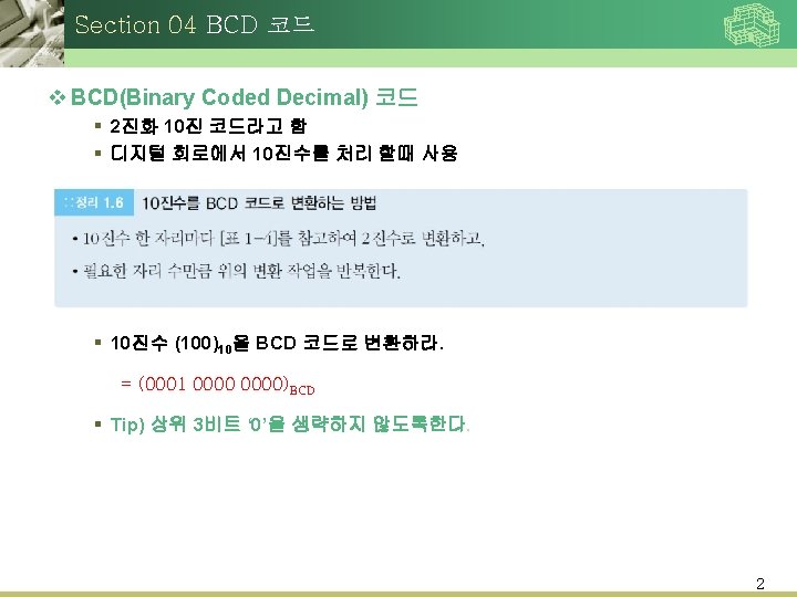
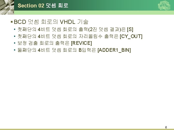
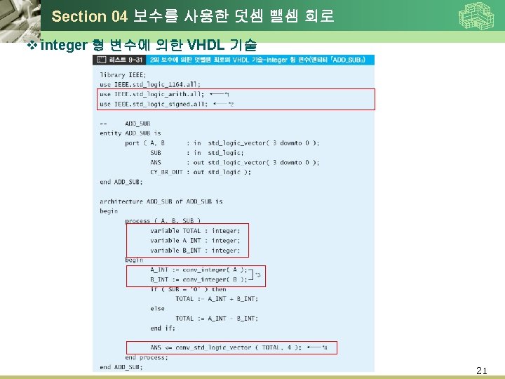
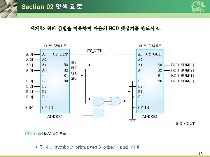
Section 02 덧셈 회로 v BCD 덧셈 회로 BCD 코드에서 십진수 (16)BCD = 0001 0101 1

Section 02 덧셈 회로 7

Section 02 덧셈 회로 9

Section 02 덧셈 회로 10

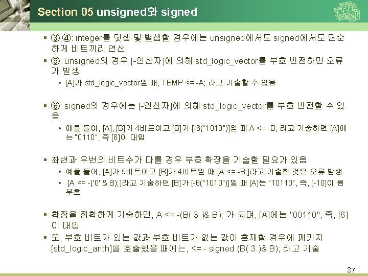
Section 05 unsigned와 signed 24

Section 05 unsigned와 signed 26

Section 05 unsigned와 signed 30

Section 05 unsigned와 signed New Project > 33

Section 05 unsigned와 signed New Project > 34

Section 05 unsigned와 signed New Project > 35

Section 05 unsigned와 signed File>New>Block Diagram/schematic file 바탕화면 마우스 오른쪽 클릭 -> insert > Symbol Fulladder directory에서 파일로드 36

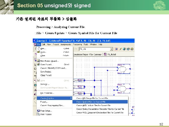
Section 05 unsigned와 signed 37
![Section 05 unsigned와 signed 이하 Process는 동일함 A[0], B[0] 주기 10 ns A[0], B[0]](http://slidetodoc.com/presentation_image_h2/a72fba642a4ebbc4571957e1f9212149/image-38.jpg "Section 05 unsigned와 signed 이하 Process는 동일함 A[0], B[0] 주기 10 ns A[0], B[0]")
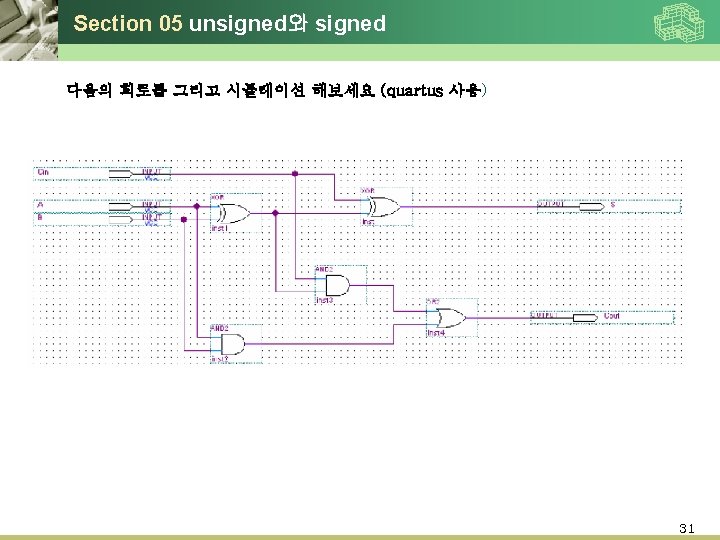
Section 05 unsigned와 signed 이하 Process는 동일함 A[0], B[0] 주기 10 ns A[0], B[0] 주기 20 ns A[0], B[0] 주기 30 ns A[0], B[0] 주기 40 ns Cin 주기 10 ns 로 셋팅하여 출력을 확인하시요. 38

Section 05 unsigned와 signed 예제 3> 다음의 4 x 1 MUX VHDL 구문을 이용 quartus로 compile, simulation 후 시뮬레이션 결과를 나타내라. (리스트 5. 17 사용) - Compile 후 VHDL 구문을 나타낸 화면에서 processing > Generate functional simulation netlist 를 클릭한후 - Simulation 에서는 다음과 같이 설정후 start (주의 simulation mode는 functional ) 41

Section 05 unsigned와 signed 예제 3> 다음의 4 x 1 MUX VHDL 구문을 이용 quartus로 compile, simulation 후 시뮬레이션 결과를 나타내라. - Compile 후 VHDL 구문을 나타낸 화면에서 File > Create/update > Create symbol file for current file 로 심벌작성 File > new > block diagram/schematic file 생성 – 아래의 회로를 작성 이름은 A 1[1. . 0] 버스선으로 연결 -메뉴: Project > Set as top level Entity로 설정 후 compilation 이후에 file> new > vector wave file 설정 -> simulation 42

Section 05 unsigned와 signed 예제 3> 다음의 4 x 1 MUX VHDL 구문을 이용 quartus로 compile, simulation 후 시뮬레이션 결과를 나타내라. 43

Section 05 unsigned와 signed VHDL 구문으로의 변환 44
- Slides: 44