Secondary Storage Devices Magnetic Disks Optical Disks Floppy


- Slides: 74

Secondary Storage Devices: Magnetic Disks Optical Disks Floppy Disks Magnetic Tapes CENG 351 1

Secondary Storage Devices Ø Two major types of secondary storage devices: 1. Direct Access Storage Devices (DASDs) – – Magnetic Discs Hard disks (high capacity, low cost, fast) Floppy disks (low capacity, lower cost, slow) Optical Disks CD-ROM = (Compact disc, read-only memory 2. Serial Devices – Magnetic tapes (very fast sequential access) CENG 351 2

Storage and Files • • Storage has major implications for DBMS design! – READ: transfer data from disk to main memory (RAM). – WRITE: transfer data from RAM to disk. – Both operations are high-cost operations, relative to in-memory operations, so DB must be planned carefully! Why Not Store Everything in Main Memory? – Costs too much: Cost of RAM about 100 times the cost of the same amount of disk space, so relatively small size. – Main memory is volatile. – Typical storage hierarchy: • Main memory (RAM) (primary storage) for currently used data. • Disk for the main database (secondary storage). • Tapes for archiving older versions of the data (tertiary storage). CENG 351 3

Storage Hierarchy • • Primary storage : random access memory (RAM) – typical capacity a number of GB – cost per MB $2 -3. 00 – typical access time 5 ns to 60 ns Secondary storage: magnetic disk/ optical devices/ tape systems – typical capacity a number of 100 GB for fixed media; for removable – cost per MB $0. 01 for fixed media, more for removable – typical access time 8 ms to 12 ms for fixed media, larger for removable CENG 351 4

Units of Measurement Spatial units: o byte: 8 bits o kilobyte (KB): 1024 or 210 bytes o megabyte (MB): 1024 kilobytes or 220 bytes o gigabyte (GB): 1024 megabytes or 230 bytes Time units: o nanosecond (ns) one- billionth (10 -9 ) of a second o microsecond ( s) one- millionth (10 -6 ) of a second o millisecond (ms) one- thousandth (10 -3 ) of a second Primary versus Secondary Storage – Primary storage costs several hundred times as much per unit as secondary storage, but has access times that are 250, 000 to 1, 000 times faster than secondary storage. CENG 351 5

Memory Hierarchy – At the primary storage level, the memory hierarchy includes, at the most expensive end’ cache memory, which is a static RAM (Random Access Memory). – The next level of primary storage is DRAM (Dynamic RAM), The advantage of DRAM is its low cost, lower speed compared with static RAM. – Programs normally reside and execute in DRAM. – Now that personal computers and workstations have 10 s of gigabytes of data in DRA, in some cases, entire databases can be kept in the main memory (with a backup copy on magnetic disk), leading to main memory databases. CENG 351 6

Memory Hierarchy-flash memory – Flash memory, since 1988 it has become common, particularly because it is nonvolatile, using EEPROM (Electrically Erasable Programmable Read-Only Memory) technology. Its life is 10, 0001, 000 times erase… Read/write is fast, but erase is slow… – Therefore special arrangements are made for the file system, regarding file delete or update. – Capacities up to 128 GB has been realized todate. CENG 351 7

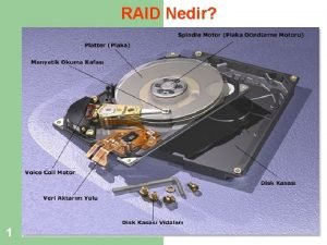
Magnetic Disks • Bits of data (0’s and 1’s) are stored on circular magnetic platters called disks. • A disk rotates rapidly (& never stops). • A disk head reads and writes bits of data as they pass under the head. • Often, several platters are organized into a disk pack (or disk drive). CENG 351 8

A Disk Drive surfaces Boom Spindle Read/Write heads Disk drive with 4 platters and 8 surfaces and 8 RW heads CENG 351 9

Looking at a surface tracks sector Surface of disk showing tracks and sectors CENG 351 10

Organization of Disks • Disk contains concentric tracks. • Tracks are divided into sectors • A sector is the smallest addressable unit in a disk. CENG 351 11

Components of a Disk head v Spindle Tracks The platters spin (say, 90 rps). The arm assembly is moved in or out to position a head on a desired track. Tracks under heads make a cylinder (imaginary!). v Sector Arm movement Only one head reads/writes at any one time. v Platters Arm assembly Block size is a multiple of sector size (which is often fixed). v CENG 351 12

Disk Controller • Disk controllers: typically embedded in the disk drive, which acts as an interface between the CPU and the disk hardware. • The controller has an internal cache (typically a number of MBs) that it uses to buffer data for read/write requests. CENG 351 13

Accessing Data • When a program reads a byte from the disk, the operating system locates the surface, track and sector containing that byte, and reads the entire sector into a special area in main memory called buffer. • The bottleneck of a disk access is moving the read/write arm. – So it makes sense to store a file in tracks that are below/above each other on different surfaces, rather than in several tracks on the same surface. CENG 351 14

Cylinders • A cylinder is the set of tracks at a given radius of a disk pack. – i. e. a cylinder is the set of tracks that can be accessed without moving the disk arm. • All the information on a cylinder can be accessed without moving the read/write arm. CENG 351 15

Cylinders CENG 351 16

Estimating Capacities • • Track capacity = # of sectors/track * bytes/sector Cylinder capacity = # of tracks/cylinder * track capacity Drive capacity = # of cylinders * cylinder capacity Number of cylinders = # of tracks in a surface CENG 351 17

Exercise • Store a file of 20000 records on a disk with the following characteristics: # of bytes per sector = 512 # of sectors per track = 40 # of tracks per cylinder = 11 # of cylinders = 1331 Q 1. How many cylinders does the file require if each data record requires 256 bytes? Q 2. What is the total capacity of the disk? CENG 351 18

Organizing Tracks by sector 6 10 7 5 3 6 4 8 2 7 3 9 9 11 2 5 10 1 11 4 1 Physically adjacent sectors 8 Sectors with 3: 1 interleaving CENG 351 19

Exercise • Suppose we want to read consecutively the sectors of a track in order: sectors 1, 2, … 11. • Suppose two consecutive sectors cannot be read in non-interleaving case. • How many revolutions to read the disk? a) Without interleaving b) With 3: 1 interleaving • Note: nowadays most disk controllers are fast enough so interleaving is not common. . . CENG 351 20

Clusters • Usually File manager, under the operating system, maintains the logical view of a file. • File manager views the file as a series of clusters, each of a number of sectors. The clusters are ordered by their logical order. • Files can be seen in the form of logical sectors or blocks, which needs to be mapped to physical clusters. • File manager uses a file allocation table (FAT) to map logical sectors of the file to the physical clusters. CENG 351 21

Extents • If there is a lot of room on a disk, it may be possible to make a file consist entirely of contiguous clusters. Then we say that the file is one extent. (very good for sequential processing) • If there isn’t enough contiguous space available to contain an entire file, the file is divided into two or more noncontiguous parts. Each part is a separate extent. CENG 351 22

Internal Fragmentation Ø Internal fragmentation: loss of space within a sector or a cluster. 1) Due to records not fitting exactly in a sector: e. g. Sector size is 512 and record size is 300 bytes. Either – store one record per sector, or – allow records span sectors… 2) Due to the use of clusters: If the file size is not a multiple of the cluster size, then the last cluster will be partially used. CENG 351 23

Choice of cluster size Ø Some operating systems allow system administrator to choose cluster size. • When to use large cluster size? • What about small cluster size? CENG 351 24

Organizing Tracks by Block • Disk tracks may be divided into user-defined blocks rather than into sectors. • Blocks can be fixed or variable length. • A block is usually organized to hold an integral number of logical records. • Blocking Factor = number of records stored in a block. • No internal fragmentation, no record spanning over two blocks. • In block-addressing scheme each block of data may be accompanied by one or more subblocks containing extra information about the block: record count, last record key on the block… CENG 351 25

Non-data Overhead • Both blocks and sectors require non-data overhead (written during formatting) • On sector addressable disks, this information involves sector address, track address, and condition (usable/defective). Also pre-formatting involves placing gaps and synchronization marks between the sectors. • On block-organized disk, where a block may be of any size, more information is needed and the programmer should be aware of some of this information to utilize it for better efficiency… CENG 351 26

Exercise • Consider a block-addressable disk with the following characteristics: – Size of track 20, 000 bytes. – Nondata overhead per block = 300 bytes. – Record size = 100 byte. • Q) How many records can be stored per track if blocking factor is 10 or 60? a) 10 (20000/1300*10=150) b) 60 (20000/6300*60=180) CENG 351 27

The Cost of a Disk Access Ø The time to access a sector in a track on a surface is divided into 3 components: Time Component Action Seek Time to move the read/write arm to the correct cylinder Rotational delay (or latency) Time it takes for the disk to rotate so that the desired sector is under the read/write head Transfer time Once the read/write head is positioned over the data, this is the time it takes for transferring data CENG 351 28

Seek time • Seek time is the time required to move the arm to the correct cylinder. • Largest in cost. Typically: – 5 ms (miliseconds) to move from one track to the next (track-to-track) – 50 ms maximum (from inside track to outside track) – 30 ms average (from one random track to another random track) CENG 351 29

Average Seek Time (s)-1 • It is usually impossible to know exactly how many tracks will be traversed in every seek, – we usually try to determine the average seek time (s) required for a particular file operation. • If the starting positions for each access are random, it turns out that the average seek traverses one third of the total number of cylinders. – Why? There are more ways to travel short distance than to travel long distance… • Manufacturer’s specifications for disk drives often list this figure as the average seek time for the drives. • Most hard disks today have s under 10 ms, and high-performance disks have s as low as 7. 5 ms. 30 CENG 351

Average Seek Time (s)-2 • Seek time depends only on the speed with which the head rack moves, and the number of tracks that the head must move across to reach its target. • Given the following (which are constant for a particular disk): – Hs = the time for the I/ O head to start moving – Ht = the time for the I/ O head to move from one track to the next • Then the time for the head to move n tracks is: • Seek(n)= Hs+ Ht*n CENG 351 31

Latency (Rotational Latency)-1 • Latency is the time needed for the disk to rotate so the sector we want is under the read/write head. • Hard disks usually rotate at about 5000 -7000 rpm, – 12 -8 msec per revolution. • Note: – Min latency = 0 – Max latency = Time for one disk revolution – Average latency (r) = (min + max) / 2 = max / 2 = time for ½ disk revolution • Typically 6 – 4 ms, at average CENG 351 32

Rotational Latency-2 • Given the following: – R = the rotational speed of the spindle (in rotations per second) – = the number of radians through which the track must rotate – then the rotational latency radians is: • Latency= ( /2 )*(1000/R), in ms CENG 351 33

Transfer Time-1 • Transfer time is the time for the read/write head to pass over a block. • The transfer time is given by the formula: number of sectors Transfer time = ----------------- x rotation time track capacity in number of sectors – e. g. if there are St sectors per track, the time to transfer one sector would be 1/ St of a revolution. CENG 351 34

Transfer Time-2 • The transfer time depends only on the speed at which the spindle rotates, and the number of sectors that must be read. • Given: – St = the total number of sectors per track – the transfer time for n contiguous sectors on the same track is: • Transfer Time =(n/St)*(1000/R), in ms CENG 351 35

Exercise Given the following disk: – 20 surfaces 800 tracks/surface 25 sectors/track 512 bytes/sector – 3600 rpm (revolutions per minute) – 7 ms track-to-track seek time 28 ms avg. seek time 50 ms max seek time. Find: a) Average latency b) Disk capacity c) Time to read the entire disk, one cylinder at a time CENG 351 36

Exercise • Disk characteristics: – Average seek time = 8 msec. – Average rotational delay = 3 msec – Maximum rotational delay = 6 msec. – Spindle speed = 10, 000 rpm – Sectors per track = 170 – Sector size = 512 bytes • Q) What is the average time to read one sector? CENG 351 37

Sequential Reading • Given the following disk: – Avg. Seek time s = 16 ms – Avg. Rot. Latency r = 8. 3 ms – Block transfer time = 8. 4 ms a) Calculate the time to read 10 sequential blocks, on the same track. b) Calculate the time to read 10 sequential cylinders, if there are 200 cylinders, and 20 surfaces. CENG 351 38

Random Reading Given the same disk, a) Calculate the time to read 100 blocks randomly b) Calculate the time to read 100 blocks sequentially. CENG 351 39

Fast Sequential Reading • We assume that blocks are arranged so that there is no rotational delay in transferring from one track to another within the same cylinder. This is possible if consecutive track beginnings are staggered (like running races on circular race tracks) • We also assume that the consecutive blocks are arranged so that when the next block is on an adjacent cylinder, there is no rotational delay after the arm is moved to new cylinder • Fast sequential reading: no rotational delay after finding the first block. CENG 351 40

Assuming Fast Reading, Consequently Reading b blocks: i. Sequentially: s + r + b * btt insignificant for large files, where b is very large: b * btt ii. Randomly: b * (s + r + btt) CENG 351 41

Exercise • Given a file of 30000 records, 1600 bytes each, and block size 2400 bytes, how does record placement affect sequential reading time, in the following cases? Discuss. i) Empty space in blocks-internal fragmentation. ii) Records overlap block boundaries. CENG 351 42

Exercise • Specifications of a disk drive: – – – Min seek time, track-to-track = 6 ms. Average seek time = 18 ms Rotational delay = 8. 3 ms Transfer time or byte transfer rate=16. 7 ms/track or 1229 bytes/ms Bytes per sector = 512 Sectors per track = 40 Tracks per cylinder = 12 (number of surfaces) Tracks per surface = 1331 Non Interleaving Cluster size= 8 sectors Smallest extent size = 5 clusters Q) How long will it take to read a 2048 KB file that is divided into 8000 records, each record 256 bytes? i) ii) Access the file sequentially, ie. In physical order. Access the file randomly, in some logical record order. CENG 351 43

Secondary Storage Devices: Magnetic Tapes CENG 351 44

Characteristics • No direct access, but very fast sequential access. • Resistant to different environmental conditions. • Easy to transport, store, cheaper than disk. • Before it was widely used to store application data; nowadays, it’s mostly used for backups or archives. CENG 351 45

MT Characteristics-2 • A sequence of bits are stored on magnetic tape. • For storage, the tape is wound on a reel. • To access the data, the tape is unwound from one reel to another. • As the tape passes the head, bits of data are read from or written onto the tape. CENG 351 46

Reel 2 Reel 1 tape Read/write head CENG 351 47

Tracks • Typically data on tape is stored in 9 separate bit streams, or tracks. • Each track is a sequence of bits. • Recording density = # of bits per inch (bpi). Typically 800 or 1600 bpi. 30000 bpi on some recent devices. CENG 351 48

MT recording in detail 8 bits = 1 byte … … … 0 1 1 0 1 1 0 1 0 … ½” … … parity bit CENG 351 49

Tape Organization logical record 2400’ … BOT marker Data blocks Header block (describes data blocks) CENG 351 EOT Interblock gap marker (for acceleration & deceleration of tape) 50

Data Blocks and Records • Each data block is a sequence of contiguous records. • A record is the unit of data that a user’s program deals with. • The tape drive reads an entire block of records at once. • Unlike a disk, a tape starts and stops. • When stopped, the read/write head is over an interblock gap. CENG 351 51

Example: tape capacity • Given the following tape: – Recording density = 1600 bpi – Tape length = 2400 ' – Interblockgap = ½ " – 512 bytes per record – Blocking factor = 25 • How many records can we write on the tape? (ignoring BOT and EOT markers and the header block for simplicity) CENG 351 52

Secondary Storage Devices: CD-ROM CENG 351 53

Physical Organization of CD-ROM • Compact Disk – read only memory (write once), R/W is also available. • Data is encoded and read optically with a laser • Can store around +600 MB data • Digital data is represented as a series of Pits and Lands: – Pit = a little depression, forming a lower level in the track – Land = the flat part between pits, or the upper levels in the track CENG 351 54

Organization of data • Reading a CD is done by shining a laser at the disc and detecting changing reflections patterns. – 1 = change in height (land to pit or pit to land) – 0 = a “fixed” amount of time between 1’s LAND PIT LAND. . . ------+ +-------+ +---. . . |_____| |_______|. . 0 0 1 0 0 0 1 0 0. . • Note : we cannot have two 1’s in a row! => uses Eight to Fourteen Modulation (EFM) encoding table. Usually, a pattern of 8 bits is translated to/from a pattern of 14 pits and lands. CENG 351 55

CD-ROM • · While the speed of CD-ROM readers is relatively higher, such as 24 X(24 times CD audio speed), the speed of writing is much slower, as low as 2 X. – Note that the speed of the audio is about 150 KB per second. • ·The DVD (Digital Video Disc or Digital Versatile Disc) technology is based on CD technology with increased storage density. • The DVD technology allows two-side medium, with a storage capacity of up to 10 GB. CENG 351 56

CD-ROM • • • Because of the heritage from CD audio, the data is stored as a single spiral track on the CD-ROM, contrary to magnetic hard disk’s discrete track concept. Thus, the rotation speed is controlled by CLV-Constant Linear velocity. The rotational speed at the center is highest, slowing down towards the outer edge. Because, the recording density is the same every where. Note that with CLV, the linear speed of the spiral passing under the R/W head remains constant. CLV is the culprit for the poor seek time in CD-ROMs The advantage of CLV is that the disk is utilized at its best capacity, as the recording density is the same every where. CENG 351 57

CD-ROM • Note that: Since 0's are represented by the length of time between transitions, we must travel at constant linear velocity (CLV)on the tracks. • Sectors are organized along a spiral • Sectors have same linear length • Advantage: takes advantage of all storage space available. • Disadvantage: has to change rotational speed when seeking (slower towards the outside) CENG 351 58

CD-ROM • Question: Why does it take only 70 minutes of playing time in an CD audio. · Ans. : If the sound frequency is 20 kilohertz, we need twice as much frequency for sampling speed to reconstruct the sound wave. Each sample may take up to 2 bytes. – -An accepted standard allows a sampling speed of 44100 times per second, which requires 88200 bytes for 2 bytes per sample. For stereo, this becomes 176400 bytes per second. If – -If the capacity is about 600 MB, you can compute number of minutes required… CENG 351 59

Addressing • 1 second of play time is divided up into 75 sectors. • Each sector holds 2 KB • 60 min CD: 60 min * 60 sec/min * 75 sectors/sec = 270, 000 sectors = 540, 000 KB ~ 540 MB • A sector is addressed by: Minute: Second: Sector e. g. 16: 22: 34 CENG 351 60

File Structures for CD-ROM • One of the problems faced in using CDs for data storage is acceptance of a common file system, with the following desired design goals: – Support for hierarchical directory structure, with access of one or two seeks… – Support for generic file names (as in “file*. c”), during directory access • If implement UNIX file system on CD-ROM, it will be a catastrophe! The seek time per access is from 500 msec to 1 sec. CENG 351 61

File Structures for CD-ROM • In this case, one seek may be necessary per subdirectory. For example /usr/home/mydir/ceng 351/exam 1 will require five seeks to locate the file exam 1 only… • Solution – One approach place the entire directory structure in one file, such that it allows building a left child right sibling structure to be able to access any file. • For a small file structure file, the entire directory structure can be kept in the memory all the time, which allows method to work. CENG 351 62

File Structures for CD-ROM • The second approach is to create an index to the file locations by hashing the full path names of each file. • This method will not work for generic file or directory searches. • A third method may utilize both above methods, one can keep the advantage of Unix like one file per directory scheme, at the same time allows building indexes for the subdirectories. CENG 351 63

File Structures for CD-ROM • A forth method, assume directories as files as well and use a special index that organizes the directories and the files into a hierarchy where a simple parental index indicates the relationship between all entries. Rec Number 0 Root 1 Subdir 1 2 Subdir 11 3 Subdir 12 4 File 11 5 File 6 Subdir 2 File or dir name Parent 0 1 1 1 0 0 CENG 351 64

Representation of individual files on CD-ROM • B+ Tree type data structures are appropriate for organizing the files on CD-ROMs. • Build once read many times allows attempting to achieve 100% utilization of blocks or buckets. Packing the internal nodes so that all of them can be maintained in the memory during the data fetches is important. • Secondary indexes can be formed so that the records are pined to the indexes on a CD-ROM, as the file will never be reorganized… CENG 351 65

Representation of individual files on CD-ROM • This may force the files on the source disks and their copies on the CD-ROM to be differently organized, because of the efficiency concerns. • It is possible to use hashing on the CD-ROM, except that the overflow should either not exist or minimized. This becomes possible when the addressing space is kept large. • Remember that the files to be put on a CD-ROM are final, so the hashing function can be chosen to perform the best, i. e. with no collisions. CENG 351 66

A journey of a Byte and Buffer Management Reference: Sections 3. 8 & 3. 9 CENG 351 67

A journey of a byte • Suppose in our program we wrote: outfile << c; • This causes a call to the file manager (a part of O. S. responsible for I/O operations) • The O/S (File manager) makes sure that the byte is written to the disk. • Pieces of software/hardware involved in I/O: – – Application Program Operating System/ file manager I/O Processor Disk Controller CENG 351 68

• Application program – Requests the I/O operation • Operating system / file manager – – Keeps tables for all opened files Brings appropriate sector to buffer. Writes byte to buffer Gives instruction to I/O processor to write data from this buffer into correct place in disk. – Note: the buffer is an exact image of a cluster in disk. • I/O Processor – a separate chip; runs independently of CPU – Find a time when drive is available to receive data and put dat in proper format for the disk – Sends data to disk controller • Disk controller – A separate chip; instructs the drive to move R/W head – Sends the byte to th surface when the proper sector comes under R/W head. CENG 351 69

Buffer Management • Buffering means working with large chunks of data in main memory so the number of accesses to secondary storage is reduced. • Today, we’ll discuss the System I/O buffers. These are beyond the control of application programs and are manipulated by the O. S. • Note that the application program may implement its own “buffer” – i. e. a place in memory (variable, object) that accumulates large chunks of data to be later written to disk as a chunk. • Read Section 4. 2 for using classes to manipulate program buffers. CENG 351 70

System I/O Buffer Data transferred by blocks Secondary Storage Buffer Program Data transferred by records Temporary storage in MM for one block of data CENG 351 71

Buffer Bottlenecks • Consider the following program segment: while (1) { infile >> ch; if (infile. fail()) break; outfile << ch; } • What happens if the O. S. used only one I/O buffer? Buffer bottleneck • Most O. S. have an input buffer and an output buffer. CENG 351 72

Buffering Strategies • Double Buffering: Two buffers can be used to allow processing and I/O to overlap. – Suppose that a program is only writing to a disk. – CPU wants to fill a buffer at the same time that I/O is being performed. – If two buffers are used and I/O-CPU overlapping is permitted, CPU can be filling one buffer while the other buffer is being transmitted to disk. – When both tasks are finished, the roles of the buffers can be exchanged. • The actual management is done by the O. S. CENG 351 73

Other Buffering Strategies • Multiple Buffering: instead of two buffers any number of buffers can be used to allow processing and I/O to overlap. • Buffer pooling: – There is a pool of buffers. – When a request for a sector is received, O. S. first looks to see that sector is in some buffer. – If not there, it brings the sector to some free buffer. If no free buffer exists, it must choose an occupied buffer. (usually LRU strategy is used) CENG 351 74
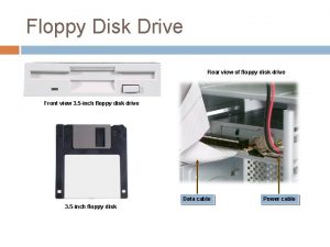
 Floppy disk secondary storage
 Types of floppy disks
 Magnetic tape in secondary memory
 Magnetic disks are the most popular medium for
 Examples of optical storage devices
 Types of optical storage
 Types of external memory
 Primary storage vs secondary storage
 Primary storage and secondary storage
 Uses rigid metallic platters
 Secondary storage devices
 Secondary storage devices that use laser technology
 Magneto optic current transducer
 Magnetic permeability of materials
 Magnetic field unit weber
 Magnetic moment and magnetic field relation
 Force on charged particle
 Unit 10 magnetic storage
 Magnetic storage
 Functions of a hard disk
 Laryngomalacia
 Vrste spoljne memorije
 Pictures of floppy eyelid syndrome
 Pengertian storage device
 Kipper floppy chip biff
 Floppy disk cleaner
 Floppy disk characteristics
 Floppy socorrismo
 Contoh storage device
 Optical devices
 Literary device scanner
 Unified storage vs traditional storage
 Basic unit of data storage
 Structure of magnetic disk
 Secondary storage device
 Secondary storage management
 Striping
 Diagram umum dari komputer
 Shadow paging
 Types of i/o devices
 Overview of physical storage media in dbms
 Cpu output device
 Types of storage devices
 Igcse ict
 Characteristics of storage devices
 Computer peripherals storage devices
 What are backing storage devices
 What is tertiary storage
 Mass storage devices are specialized high capacity
 Magnetic disk uses
 Storage devices
 Memorex 304
 Storage devices presentation
 Data tape disposal
 Tower of hanoi 4 disks
 A case for redundant arrays of inexpensive disks
 Label computer parts
 Redundant arrays of independent disks
 Disks of polycarbonate plastic from a supplier are analyzed
 Duffy's mvp levels
 Disks and tapes can be stored ------- a library. eng101
 Redundant array of independent disks
 Holger brock
 Conquest data disks
 Literary devices/techniques
 Scanner input or output
 Optical illusions science fair project hypothesis
 When light travels from an optically denser medium
 Numerical aperture formula
 Underwater optical control
 Optical vs acoustic phonons
 In a curved optical fiber light
 Optical indicatrix
 Skew rays in optical fiber
 Physical properties of amines
