
Secondary Gas Insulated Switchgear Safe Link CB 12

Secondary Gas Insulated Switchgear Safe. Link CB 12 k. V SGIS
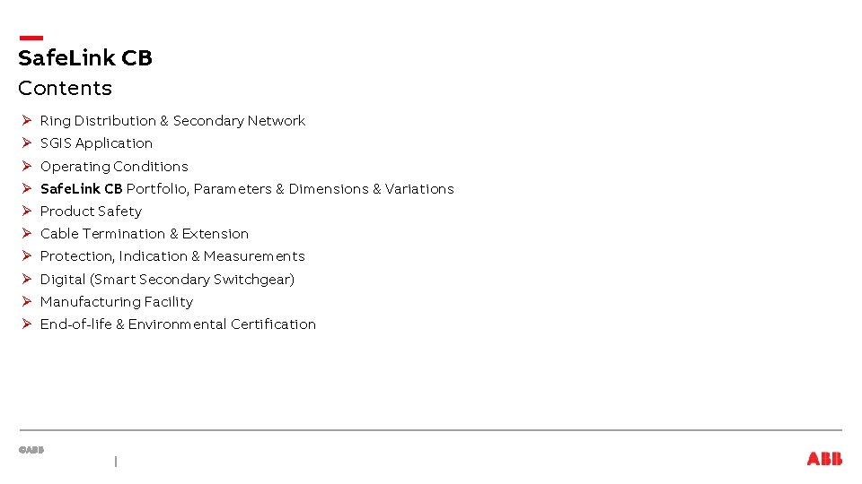
Safe. Link CB Contents Ø Ring Distribution & Secondary Network Ø SGIS Application Ø Operating Conditions Ø Safe. Link CB Portfolio, Parameters & Dimensions & Variations Ø Product Safety Ø Cable Termination & Extension Ø Protection, Indication & Measurements Ø Digital (Smart Secondary Switchgear) Ø Manufacturing Facility Ø End-of-life & Environmental Certification
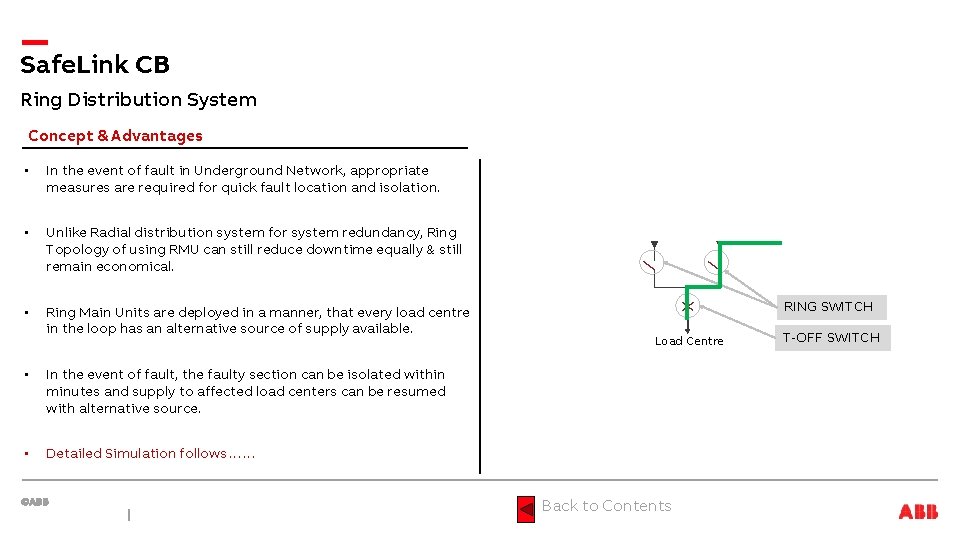
Safe. Link CB Ring Distribution System Concept & Advantages • In the event of fault in Underground Network, appropriate measures are required for quick fault location and isolation. • Unlike Radial distribution system for system redundancy, Ring Topology of using RMU can still reduce downtime equally & still remain economical. • Ring Main Units are deployed in a manner, that every load centre in the loop has an alternative source of supply available. • In the event of fault, the faulty section can be isolated within minutes and supply to affected load centers can be resumed with alternative source. • Detailed Simulation follows…… RING SWITCH Load Centre Back to Contents T-OFF SWITCH
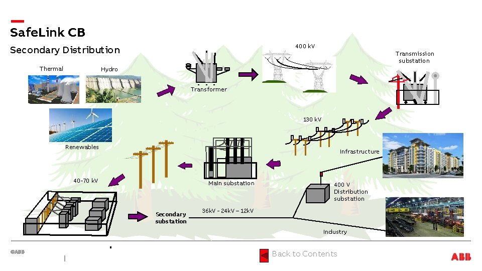
Safe. Link CB 400 k. V Secondary Distribution Thermal Transmission substation Hydro Transformer 130 k. V Renewables Infrastructure 40 -70 k. V Main substation Secondary substation 400 V Distribution substation 36 k. V - 24 k. V – 12 k. V Industry Back to Contents
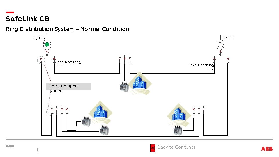
Safe. Link CB Ring Distribution System – Normal Condition 33/11 k. V Local Receiving Stn. Normally Open Points Back to Contents
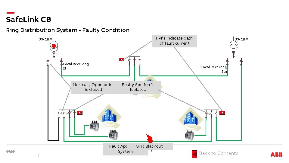
Safe. Link CB Ring Distribution System - Faulty Condition FPI’s Indicate path of fault current 33/11 k. V Local Receiving Stn. Normally Open point is closed Faulty Section is Isolated Fault Appears. Grid in Blackout! System Back to Contents
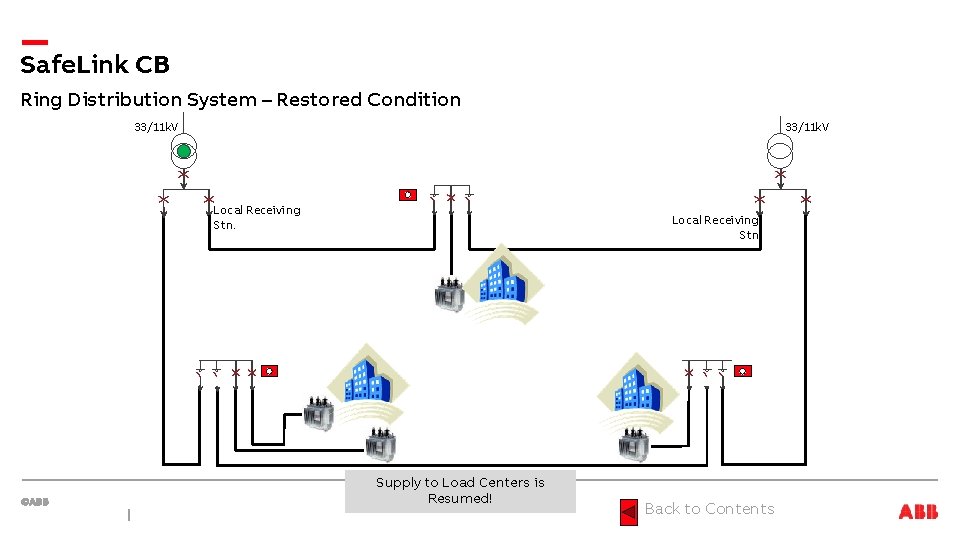
Safe. Link CB Ring Distribution System – Restored Condition 33/11 k. V Local Receiving Stn. Supply to Load Centers is Resumed! Back to Contents
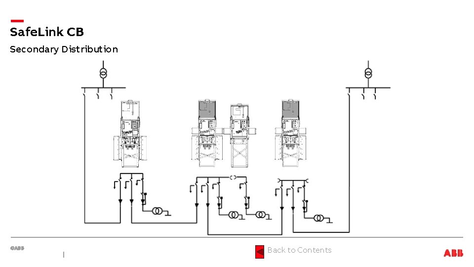
Safe. Link CB Secondary Distribution Back to Contents
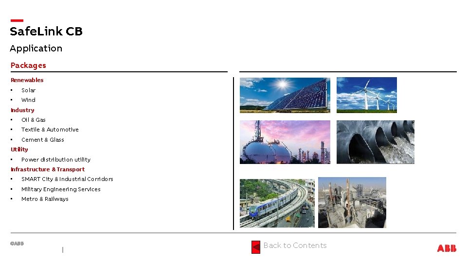
Safe. Link CB Application Packages Renewables • Solar • Wind Industry • Oil & Gas • Textile & Automotive • Cement & Glass Utility • Power distribution utility Infrastructure & Transport • SMART City & Industrial Corridors • Military Engineering Services • Metro & Railways Back to Contents
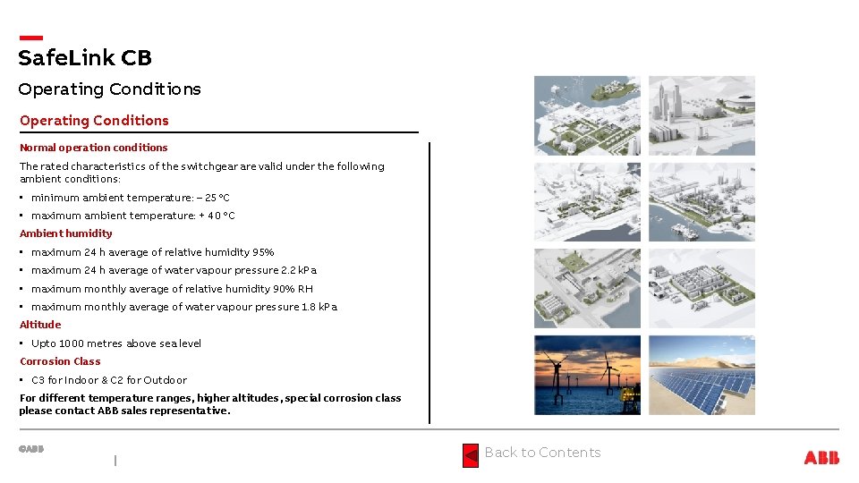
Safe. Link CB Operating Conditions Normal operation conditions The rated characteristics of the switchgear are valid under the following ambient conditions: • minimum ambient temperature: – 25 °C • maximum ambient temperature: + 40 °C Ambient humidity • maximum 24 h average of relative humidity 95% • maximum 24 h average of water vapour pressure 2. 2 k. Pa • maximum monthly average of relative humidity 90% RH • maximum monthly average of water vapour pressure 1. 8 k. Pa Altitude • Upto 1000 metres above sea level Corrosion Class • C 3 for Indoor & C 2 for Outdoor For different temperature ranges, higher altitudes, special corrosion class please contact ABB sales representative. Back to Contents
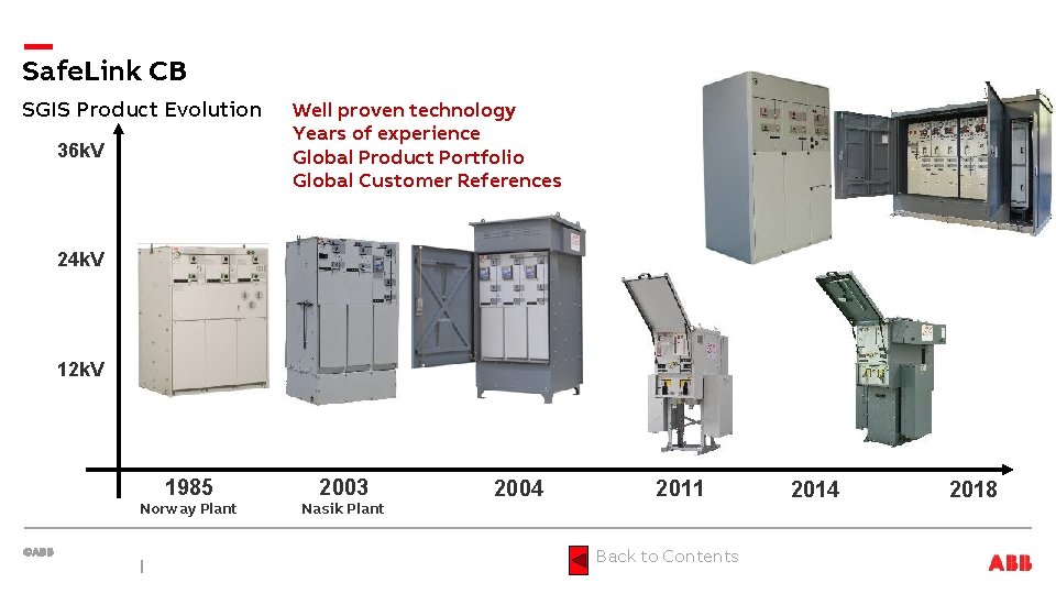
Safe. Link CB SGIS Product Evolution 36 k. V Well proven technology Years of experience Global Product Portfolio Global Customer References 24 k. V 12 k. V 1985 Norway Plant 2003 Nasik Plant 2004 2011 Back to Contents 2014 2018

Safe. Link CB SGIS Product Portfolio Product Family Safe. Ring / Safe. Plus Safe. Link CB • 2004 • 2011 • Indoor • Outdoor • 12/24 k. V • 12 k. V Safe. Ring / Safe. Plus Safe. Ring 36 / Safe. Plus 36 • 2006 • 2014 • Outdoor • Indoor/Outdoor • 12/24 k. V • 36 k. V Back to Contents
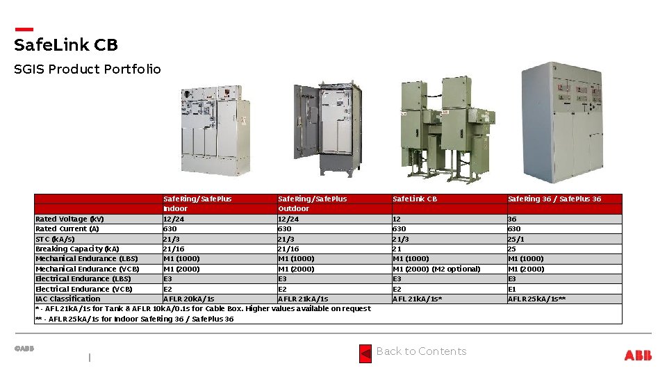
Safe. Link CB SGIS Product Portfolio Safe. Ring/Safe. Plus Indoor Outdoor Rated Voltage (k. V) 12/24 Rated Current (A) 630 STC (k. A/s) 21/3 Breaking Capacity (k. A) 21/16 Mechanical Endurance (LBS) M 1 (1000) Mechanical Endurance (VCB) M 1 (2000) Electrical Endurance (LBS) E 3 Electrical Endurance (VCB) E 2 IAC Classification AFLR 20 k. A/1 s AFLR 21 k. A/1 s * - AFL 21 k. A/1 s for Tank & AFLR 10 k. A/0. 1 s for Cable Box. Higher values available on request ** - AFLR 25 k. A/1 s for Indoor Safe. Ring 36 / Safe. Plus 36 Safe. Link CB 12 630 21/3 21 M 1 (1000) M 1 (2000) (M 2 optional) E 3 E 2 AFL 21 k. A/1 s* Back to Contents Safe. Ring 36 / Safe. Plus 36 630 25/1 25 M 1 (1000) M 1 (2000) E 3 E 1 AFLR 25 k. A/1 s**
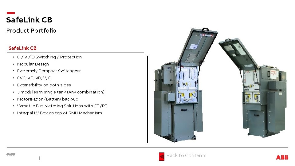
Safe. Link CB Product Portfolio Safe. Link CB • C / V / D Switching / Protection • Modular Design • Extremely Compact Switchgear • CVC, VD, V, C • Extensibility on both sides • 3 modules in single tank (Any combination) • Motorisation/Battery back-up • Versatile Bus Metering Solutions with CT/PT • Integral LV Box on top of RMU Mechanism Back to Contents
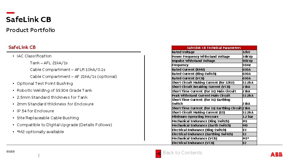
Safe. Link CB Product Portfolio Safe. Link CB • IAC Classification Tank – AFL 21 k. A/1 s Cable Compartment – AFLR 10 k. A/0. 1 s Cable Compartment – AF 21 k. A/1 s (optional) • Optional Test Point Bushing • Robotic Welding of SS 304 Grade Tank • 2. 5 mm Standard thickness for Tank • 2 mm Standard thickness for Enclosure • IP 54 for Enclosure • Site Replaceable Cable Bushing • Compatible to Digital Upgrade (Details Follows) • *M 2 optionally available Safe. Link CB Technical Parameters Rated Voltage 12 k. V Power Frequency Withstand Voltage 38 k. Vp Impulse Withstand Voltage 95 k. Vp Frequency 50 Hz Rated Current (RMU) 630 A Rated Current (Ring Switch) 630 A Rated Current (VCB) 630 A Short Circuit Making Current (for 12 k. V) 52. 5 k. A Short Circuit Breaking Current (VCB) 21 k. A Short Time Current (for 3 s) Main Circuit 21 k. A Peak Withstand Current Main Circuit 52. 5 k. A Short Time Current (for 3 s) Earthing Switch 21 k. A Short Time Current (for 1 s) Earthing Circuit 21 k. A Short Circuit Making Current (ES) 52. 5 k. A Minimum Operating Pressure 1. 2 bar Mechanical Endurance (Ring Switch) M 1 Mechanical Endurance (Earth Switch) M 0 Electrical Endurance (Ring Switch) E 3 Electrical Endurance (Earthing Switch) E 2 Mechanical Endurance (VCB) M 1* Electrical Endurance (VCB) E 2 Back to Contents
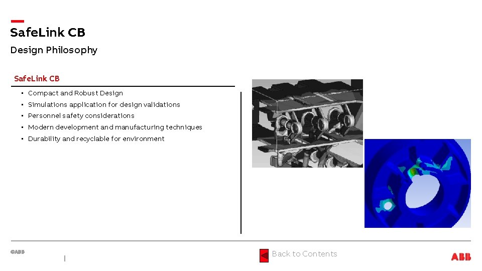
Safe. Link CB Design Philosophy Safe. Link CB • Compact and Robust Design • Simulations application for design validations • Personnel safety considerations • Modern development and manufacturing techniques • Durability and recyclable for environment Back to Contents
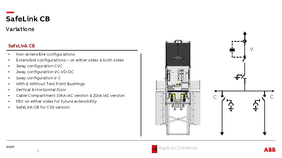
Safe. Link CB Variations Safe. Link CB • • • V Non-extensible configurations Extensible configurations – on either sides & both sides 3 way configuration CVC 2 way configuration VC-VD-DC 1 way configuration V-C With & Without Test Point Bushings Vertical & Horizontal Door Cable Compartment 10 k. A IAC version & 21 k. A IAC version PEX on either sides for future extensbility Safe. Link CB for CSS version C Back to Contents C
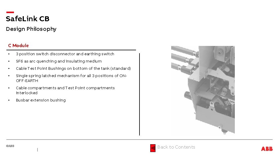
Safe. Link CB Design Philosophy C Module • 3 position switch disconnector and earthing switch • SF 6 as arc quenching and insulating medium • Cable Test Point Bushings on bottom of the tank (standard) • Single spring latched mechanism for all 3 positions of ONOFF-EARTH • Cable compartments and Test Point compartments interlocked • Busbar extension bushing Back to Contents
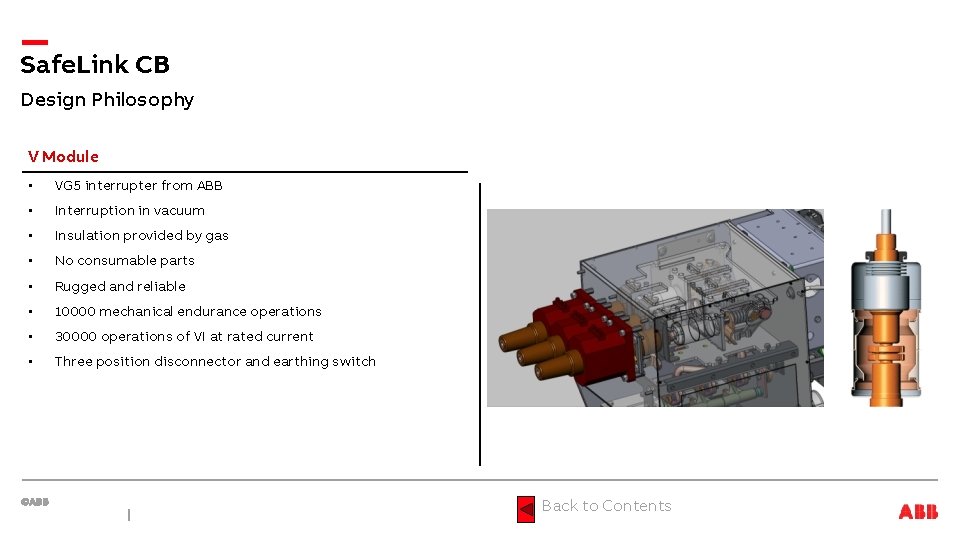
Safe. Link CB Design Philosophy V Module • VG 5 interrupter from ABB • Interruption in vacuum • Insulation provided by gas • No consumable parts • Rugged and reliable • 10000 mechanical endurance operations • 30000 operations of VI at rated current • Three position disconnector and earthing switch Back to Contents
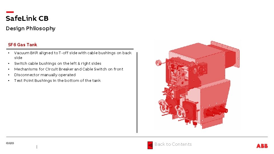
Safe. Link CB Design Philosophy SF 6 Gas Tank • • • Vacuum BKR aligned to T-off side with cable bushings on back side Switch cable bushings on the left & right sides Mechanisms for Circuit Breaker and Cable Switch on front Disconnector manually operated Test Point Bushings in the bottom of the tank Back to Contents
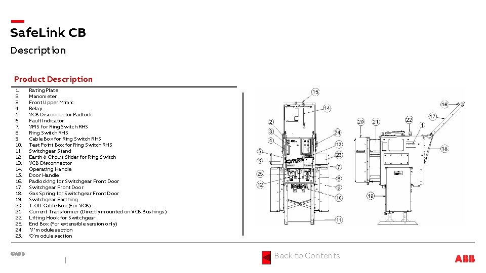
Safe. Link CB Description Product Description 1. 2. 3. 4. 5. 6. 7. 8. 9. 10. 11. 12. 13. 14. 15. 16. 17. 18. 19. 20. 21. 22. 23. 24. 25. Rating Plate Manometer Front Upper Mimic Relay VCB Disconnector Padlock Fault Indicator VPIS for Ring Switch RHS Cable Box for Ring Switch RHS Test Point Box for Ring Switch RHS Switchgear Stand Earth & Circuit Slider for Ring Switch VCB Disconnector Operating Handle Door Handle Padlocking for Switchgear Front Door Gas Spring for Switchgear Front Door Switchgear Earthing T-Off Cable Box (For VCB) Current Transformer (Directly mounted on VCB Bushings) Lifting Hook for Switchgear End Box (For extensible version only) ‘V’ module section ‘C’ module section Back to Contents
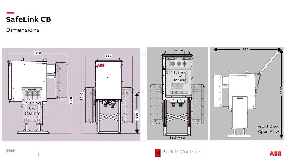
Safe. Link CB Dimensions 1830 1210 960 2020 1540 826 Bushing C-C 100 mm 1320 Bushing C-C 105 mm Front Door Open View Back to Contents
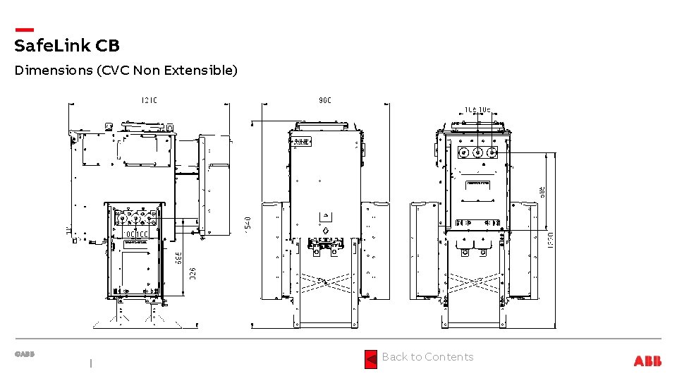
Safe. Link CB Dimensions (CVC Non Extensible) Back to Contents
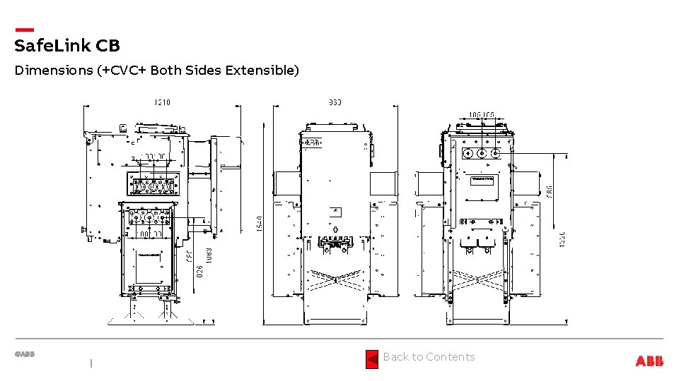
Safe. Link CB Dimensions (+CVC+ Both Sides Extensible) Back to Contents
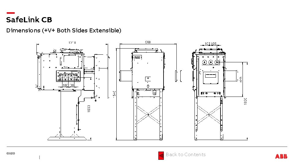
Safe. Link CB Dimensions (+V+ Both Sides Extensible) Back to Contents
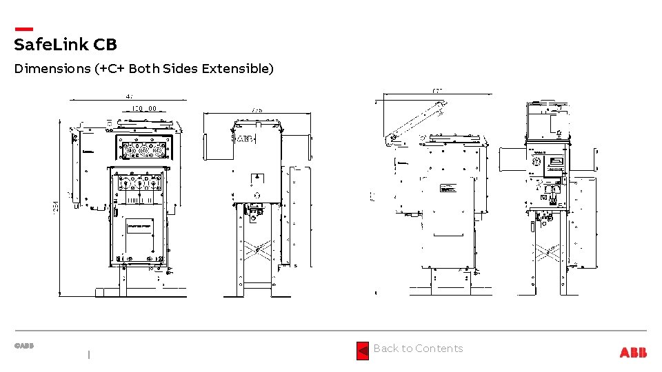
Safe. Link CB Dimensions (+C+ Both Sides Extensible) Back to Contents
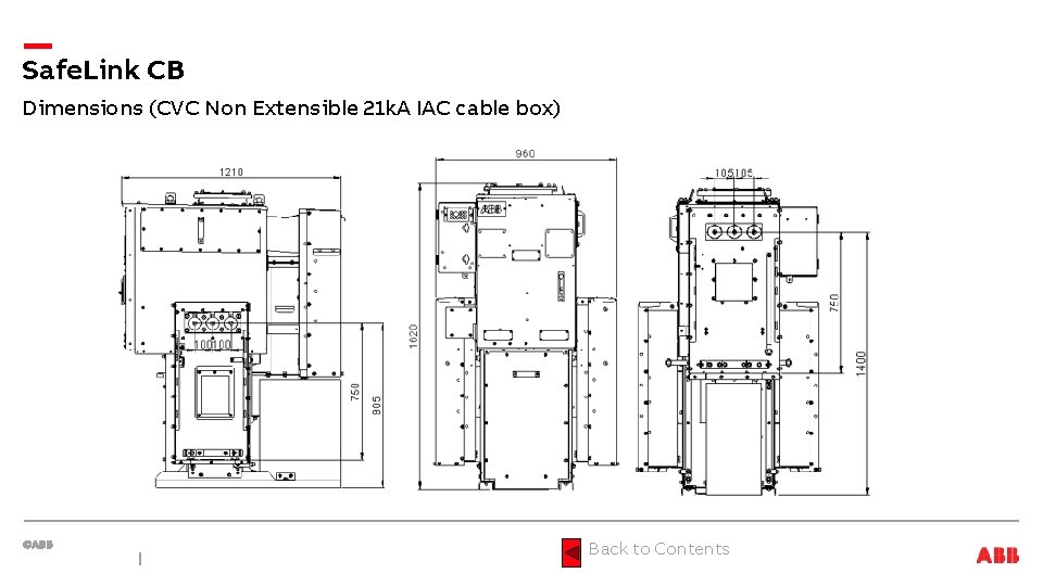
Safe. Link CB Dimensions (CVC Non Extensible 21 k. A IAC cable box) Back to Contents
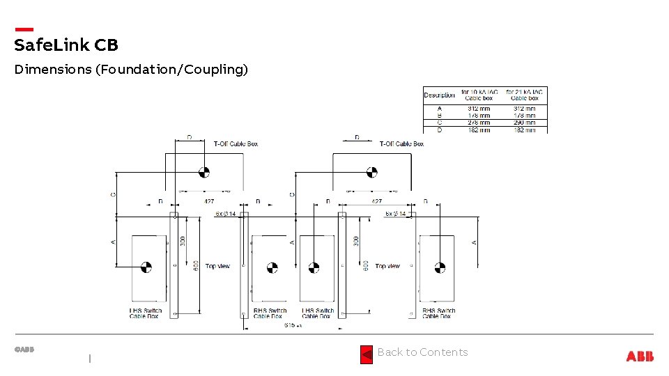
Safe. Link CB Dimensions (Foundation/Coupling) Back to Contents
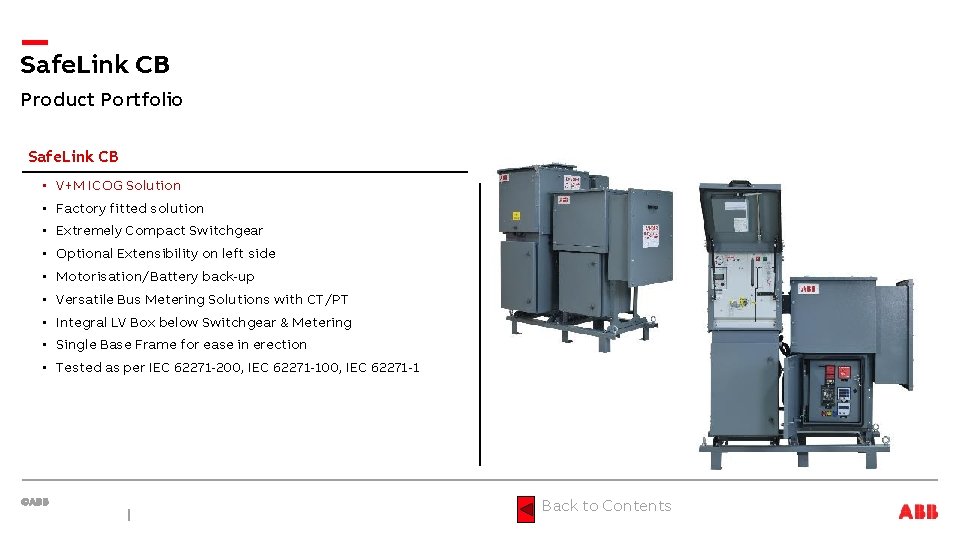
Safe. Link CB Product Portfolio Safe. Link CB • V+M ICOG Solution • Factory fitted solution • Extremely Compact Switchgear • Optional Extensibility on left side • Motorisation/Battery back-up • Versatile Bus Metering Solutions with CT/PT • Integral LV Box below Switchgear & Metering • Single Base Frame for ease in erection • Tested as per IEC 62271 -200, IEC 62271 -1 Back to Contents
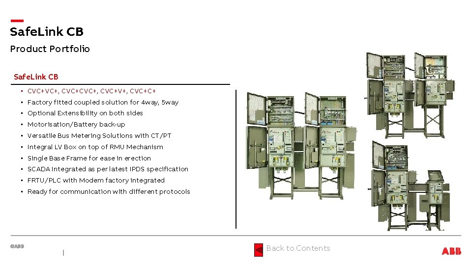
Safe. Link CB Product Portfolio Safe. Link CB • CVC+VC+, CVC+, CVC+V+, CVC+C+ • Factory fitted coupled solution for 4 way, 5 way • Optional Extensibility on both sides • Motorisation/Battery back-up • Versatile Bus Metering Solutions with CT/PT • Integral LV Box on top of RMU Mechanism • Single Base Frame for ease in erection • SCADA Integrated as per latest IPDS specification • FRTU/PLC with Modem factory integrated • Ready for communication with different protocols Back to Contents
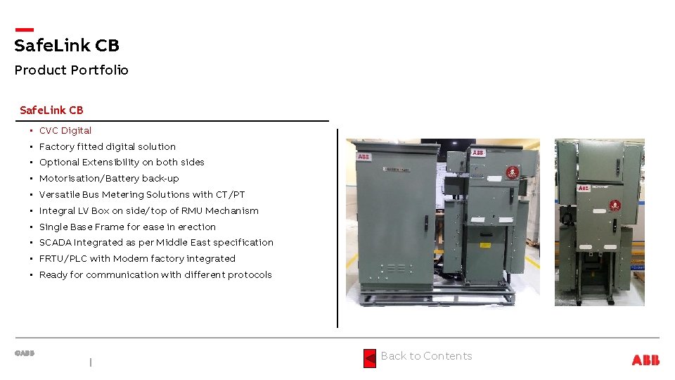
Safe. Link CB Product Portfolio Safe. Link CB • CVC Digital • Factory fitted digital solution • Optional Extensibility on both sides • Motorisation/Battery back-up • Versatile Bus Metering Solutions with CT/PT • Integral LV Box on side/top of RMU Mechanism • Single Base Frame for ease in erection • SCADA Integrated as per Middle East specification • FRTU/PLC with Modem factory integrated • Ready for communication with different protocols Back to Contents
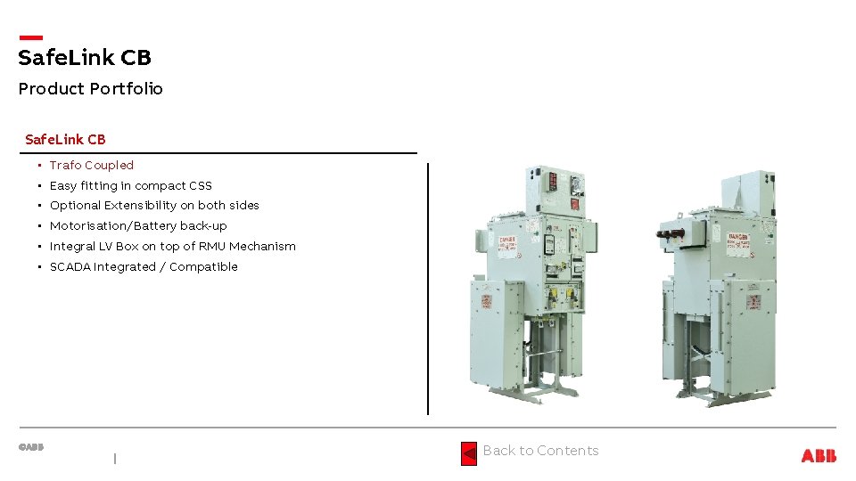
Safe. Link CB Product Portfolio Safe. Link CB • Trafo Coupled • Easy fitting in compact CSS • Optional Extensibility on both sides • Motorisation/Battery back-up • Integral LV Box on top of RMU Mechanism • SCADA Integrated / Compatible Back to Contents
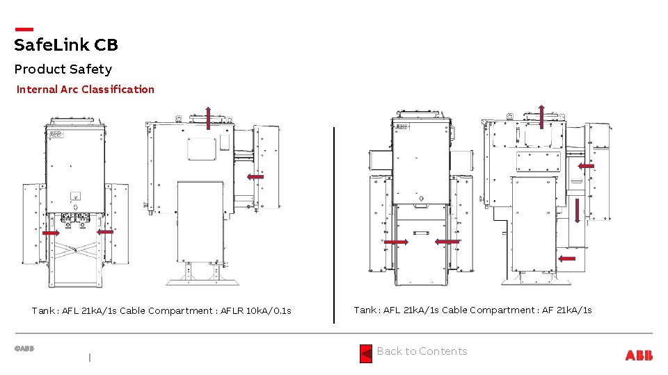
Safe. Link CB Product Safety Internal Arc Classification Tank : AFL 21 k. A/1 s Cable Compartment : AFLR 10 k. A/0. 1 s Tank : AFL 21 k. A/1 s Cable Compartment : AF 21 k. A/1 s Back to Contents
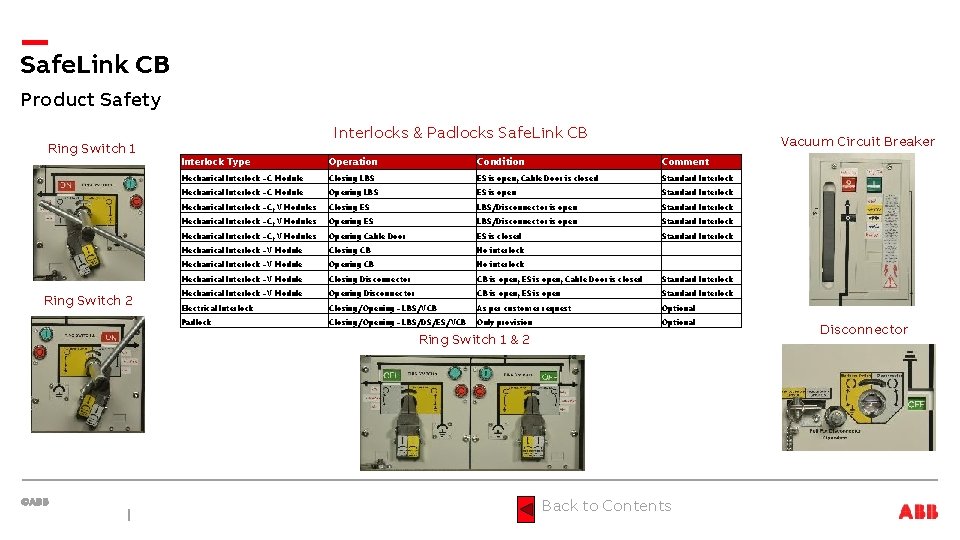
Safe. Link CB Product Safety Ring Switch 1 Ring Switch 2 Interlocks & Padlocks Safe. Link CB Vacuum Circuit Breaker Interlock Type Operation Condition Comment Mechanical Interlock - C Module Closing LBS ES is open, Cable Door is closed Standard Interlock Mechanical Interlock - C Module Opening LBS ES is open Standard Interlock Mechanical Interlock - C, V Modules Closing ES LBS/Disconnector is open Standard Interlock Mechanical Interlock - C, V Modules Opening Cable Door ES is closed Standard Interlock Mechanical Interlock - V Module Closing CB No interlock Mechanical Interlock - V Module Opening CB No interlock Mechanical Interlock - V Module Closing Disconnector CB is open, ES is open, Cable Door is closed Standard Interlock Mechanical Interlock - V Module Opening Disconnector CB is open, ES is open Standard Interlock Electrical Interlock Closing/Opening - LBS/VCB As per customer request Optional Padlock Closing/Opening - LBS/DS/ES/VCB Only provision Optional Ring Switch 1 & 2 Back to Contents Disconnector
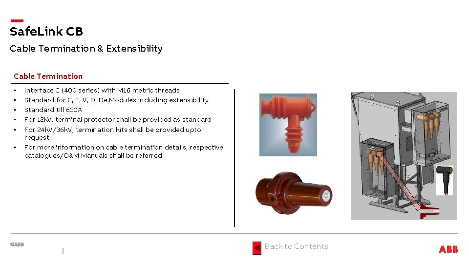
Safe. Link CB Cable Termination & Extensibility Cable Termination • • • Interface C (400 series) with M 16 metric threads Standard for C, F, V, D, De Modules including extensibility Standard till 630 A For 12 k. V, terminal protector shall be provided as standard For 24 k. V/36 k. V, termination kits shall be provided upto request. For more information on cable termination details, respective catalogues/O&M Manuals shall be referred Back to Contents
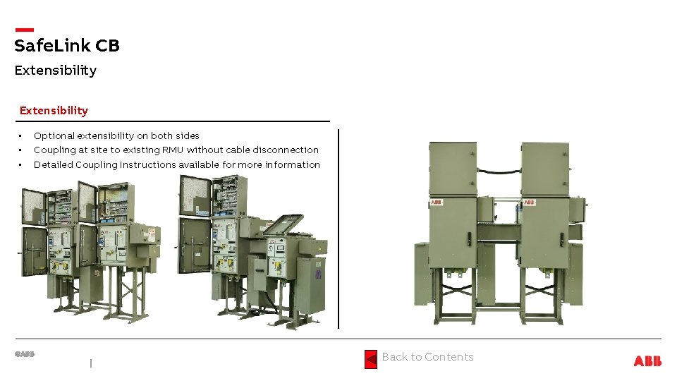
Safe. Link CB Extensibility • • • Optional extensibility on both sides Coupling at site to existing RMU without cable disconnection Detailed Coupling Instructions available for more information Back to Contents
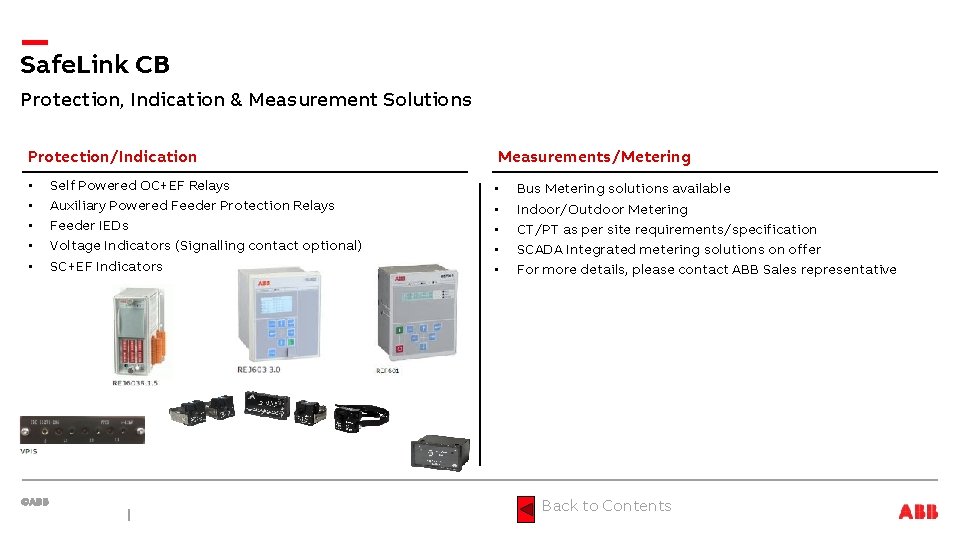
Safe. Link CB Protection, Indication & Measurement Solutions Protection/Indication • • • Self Powered OC+EF Relays Auxiliary Powered Feeder Protection Relays Feeder IEDs Voltage Indicators (Signalling contact optional) SC+EF Indicators Measurements/Metering • • • Bus Metering solutions available Indoor/Outdoor Metering CT/PT as per site requirements/specification SCADA Integrated metering solutions on offer For more details, please contact ABB Sales representative Back to Contents
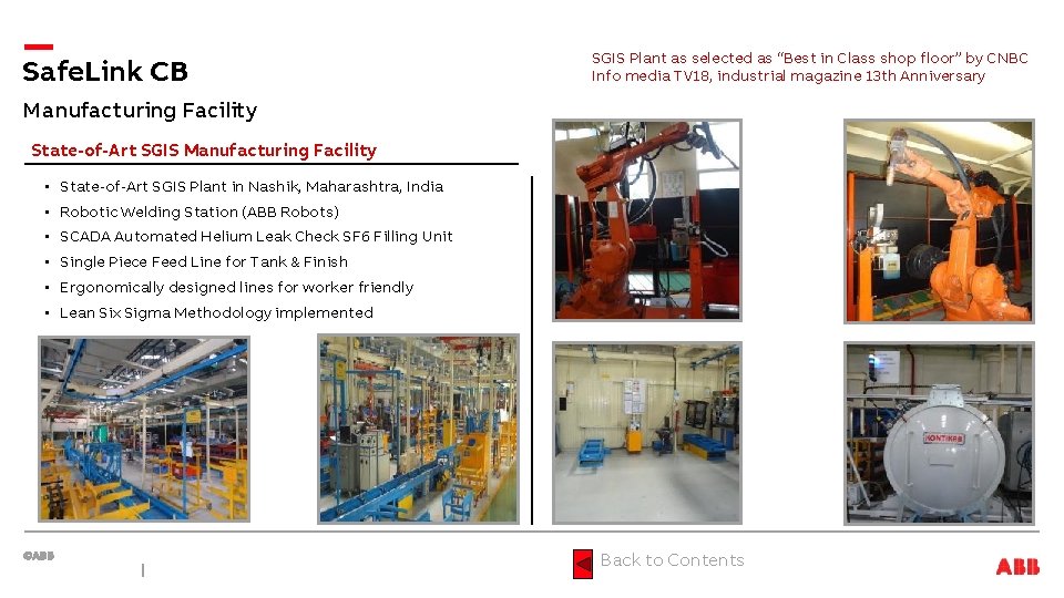
Safe. Link CB SGIS Plant as selected as “Best in Class shop floor” by CNBC Info media TV 18, industrial magazine 13 th Anniversary Manufacturing Facility State-of-Art SGIS Manufacturing Facility • State-of-Art SGIS Plant in Nashik, Maharashtra, India • Robotic Welding Station (ABB Robots) • SCADA Automated Helium Leak Check SF 6 Filling Unit • Single Piece Feed Line for Tank & Finish • Ergonomically designed lines for worker friendly • Lean Six Sigma Methodology implemented Back to Contents
Safe. Link CB Environment Certification End of Life & Environment Certification Life Expectancy of Products • Products developed in compliance with IEC 62271 -200 • Design incorporates a life span of over 20 years • Switchgear is gas-tight with expected leakage rate of < 0. 1%/yr • SF 6 Gas Pressure is 1. 4 bar • Switchgear will maintain gas-tightness (gas-pressure >=1. 3 bar) throughout its designed life span. End of Life • ABB committed to protection of the environment & adheres to ISO 14001 Standards • ABB Obligates to facilitate end of life recycling of all ABB products • No explicit requirements for how to handle discarded switchgears • ABB’s recycling service is according to IEC 1634 edition 1995 section 6: «End of life of SF 6 filled equipment» • In particular 6. 5. 2. a: «Low decomposition» : «No special action is required; non-recoverable parts can be disposed of normally according to local regulations. » Back to Contents
- Slides: 40