SEBSA System Engineering Based Safety Analysis 1 Identify


SEBSA System Engineering Based Safety Analysis 1. Identify system states and modes of operation (phases). 2. Define accidents (for each phase). Define system hazards associated with accidents. 3. Translate system hazards into high-level safety requirements (constraints). 4. Construct high-level control structure (for each phase) including: – Responsibilities of components – Preliminary process model (using UML/MSC). 5. Refine high-level safety constraints into detailed safety requirements on components and scenarios for losses. 6. Use results to create or improve system design. 7. Use results to create FTA’s when quantity analysis needed. 7 PM 12: 19: 20


דוגמא MWS - Missile Weapon System The MWS is composed of a Launcher that carries up to 4 missiles ready to fire, operated remotely one at a time. 9 PM 12: 19: 21
 1. Identify system states and modes of operation")
System Engineering Based Safety Analysis (SEBSA) 1. Identify system states and modes of operation (phases). 2. Define accidents (for each phase). Define system hazards associated with accidents. 3. Translate system hazards into high-level safety requirements (constraints). 4. Construct high-level control structure (for each phase) including: – Responsibilities of components – Preliminary process model (using UML/MSC). 5. Refine high-level safety constraints into detailed safety requirements on components and scenarios for losses. 6. Use results to create or improve system design. 7. Use results to create FTA’s when quantity analysis needed. 10 PM 12: 19: 22
 11 PM 12: 19: 22")
The Process Model - States & Modes (Using UML) 11 PM 12: 19: 22

The Process Model - States & Modes Power. On – The MWS is deployed and stabilized on ground. The user turned on the main vehicle power switch (Main. Switch 24 v) and Power. Up 28 v switch in OSP. All subsystems of the vehicle and the Launcher powered on, executing self PBIT. Idle – All subsystems of the vehicle and launcher turned on successfully and are ready to operate. Launcher. Arm – The user switched on the Launcher. Arm switch in safety panel. Missile. Partially. Power. On – The user selected missile from the HMI panel and activated it partially. It causes turning on the MMC and IMU subsystems of the selected missile (including PBIT). Missile. Power. On – The user selected missile from the HMI panel and fully activated it. It causes turning on all subsystems of the selected missile (including PBIT). Missile. Active – All subsystems of the selected missile turned on successfully and the missile is ready to launch. Ready. To. Launch – The launcher and the selected missile are ready to launch. Arm – The user pushed the ARM command bottun on the HMI panel. It starts the ARM processes in HMI and MCLU subsystems. Fire – The user pushed the FIRE command bottun on the HMI panel. It starts the FIRE processes in HMI and MCLU and MMC subsystems. Flight – Missile left the launcher. 12 PM 12: 19: 24
 1. Identify system states and modes of operation")
System Engineering Based Safety Analysis (SEBSA) 1. Identify system states and modes of operation (phases). 2. Define accidents (for each phase). Define system hazards associated with accidents. 3. Translate system hazards into high-level safety requirements (constraints). 4. Construct high-level control structure (for each phase) including: – Responsibilities of components – Preliminary process model (using UML/MSC). 5. Refine high-level safety constraints into detailed safety requirements on components and scenarios for losses. 6. Use results to create or improve system design. 7. Use results to create FTA’s when quantity analysis needed. 13 PM 12: 19: 24
 14 # Hazard Accident H 1 Missile launch")
System Engineering Based Safety Analysis (SEBSA) 14 # Hazard Accident H 1 Missile launch within prohibited zone Hit of friendly force or equipment H 2 Hangfire – Missile remains in canister after motor ignition Personnel injury or significant damage to equipment H 3 Misfire - Missile remains in canister after fire command Inadvertent warhead explosion due to reduced safety means H 4 Inadvertent missile launch Hit of friendly force or equipment H 5 Loss of missile control during flight Hit of friendly force or equipment PM 12: 19: 24
 1. Identify system states and modes of operation")
System Engineering Based Safety Analysis (SEBSA) 1. Identify system states and modes of operation (phases). 2. Define accidents (for each phase). Define system hazards associated with accidents. 3. Translate system hazards into high-level safety requirements (constraints). 4. Construct high-level control structure (for each phase) including: – Responsibilities of components – Preliminary process model (using UML/MSC). 5. Refine high-level safety constraints into detailed safety requirements on components and scenarios for losses. 6. Use results to create or improve system design. 7. Use results to create FTA’s when quantity analysis needed. 15 PM 12: 19: 24

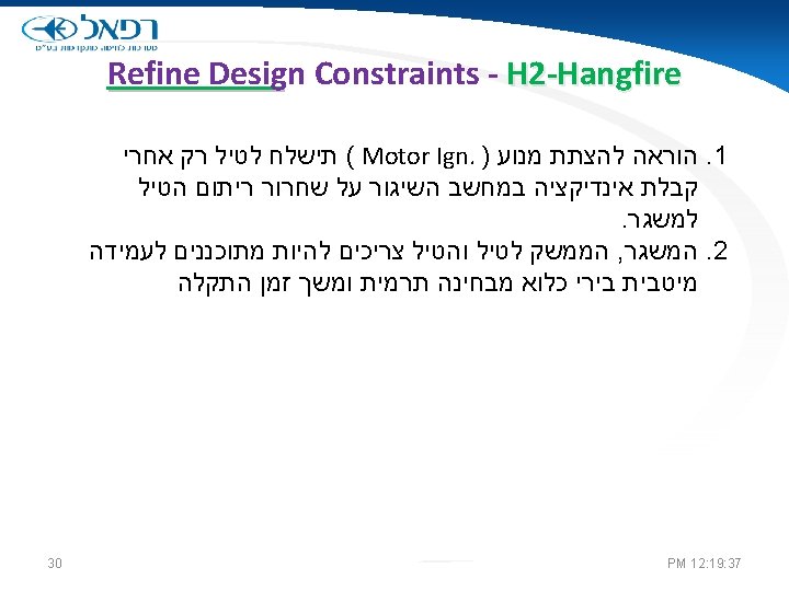
Step 3: Hazards must be translated into Design Constraint. # Hazard Safety Design Constraint H 1 Missile launch within prohibited zone 1. Means to define prohibited firing zone must be provided. 2. The system prevents launch within prohibited zone. H 2 Hang Fire – Missile remains in canister after motor ignition 1. Robust design of the interface between the missile and the canister. H 3 Misfire - Missile remains in canister after Fire command 1. Misfire indication. 2. Missile battery is discharged within 30 minutes. 3. Strict safety procedures for handling misfired missile H 4 Inadvertent missile launch 1. Prevent firing when system is not in Missile Active state. H 5 Loss of missile control during flight 1. Flight termination capability in missile. 2. Launcher angle and leveling is being measured by at least two separate techniques. 16 PM 12: 19: 25
 1. Identify system states and modes of operation")
System Engineering Based Safety Analysis (SEBSA) 1. Identify system states and modes of operation (phases). 2. Define accidents (for each phase). Define system hazards associated with accidents. 3. Translate system hazards into high-level safety requirements (constraints). 4. Construct high-level control structure (for each phase) including: – Responsibilities of components – Preliminary process model (using UML/MSC). 5. Refine high-level safety constraints into detailed safety requirements on components and scenarios for losses. 6. Use results to create or improve system design. 7. Use results to create FTA’s when quantity analysis needed. 17 PM 12: 19: 25

Step 4: Define high level control structure 18 PM 12: 19: 25

Processes in Operational Mode 19 o Preparations for Fire Process o Launch Process o Missile Ignition Process PM 12: 19: 26

Preparations for Fire Process 20 PM 12: 19: 27

Launch Process 21 PM 12: 19: 29

Missile Ignition Process 22 PM 12: 19: 30
 5. Refine high-level safety constraints into detailed safety")
System Engineering Based Safety Analysis (SEBSA) 5. Refine high-level safety constraints into detailed safety requirements on components and scenarios for losses a) Identify potential inadequate control actions that could lead to a hazardous state b) Use identified inadequate control actions to refine system safety design constraints 6. Use results to create or improve system design 7. Use results to create FTA when needed. 23 PM 12: 19: 31

Control Action analysis for: H 2 -Hangfire 24 PM 12: 19: 32
 5. Refine high-level safety constraints into detailed safety")
System Engineering Based Safety Analysis (SEBSA) 5. Refine high-level safety constraints into detailed safety requirements on components and scenarios for losses a) Identify potential inadequate control actions that could lead to a hazardous state b) Use identified inadequate control actions to refine system safety design constraints 6. Use results to create or improve system design 7. Use results to create FTA when needed. 25 PM 12: 19: 33
 Causality analysis for: H 2 -Hangfire 27 PM 12: 19: 35")
(1) Causality analysis for: H 2 -Hangfire 27 PM 12: 19: 35
 Causality analysis for: H 2 -Hangfire *לקוח מניתוח שנעשה ביחד עם ד\"ר עמית")
(2) Causality analysis for: H 2 -Hangfire *לקוח מניתוח שנעשה ביחד עם ד"ר עמית טלר 28 PM 12: 19: 36
 5. Refine high-level safety constraints into detailed safety")
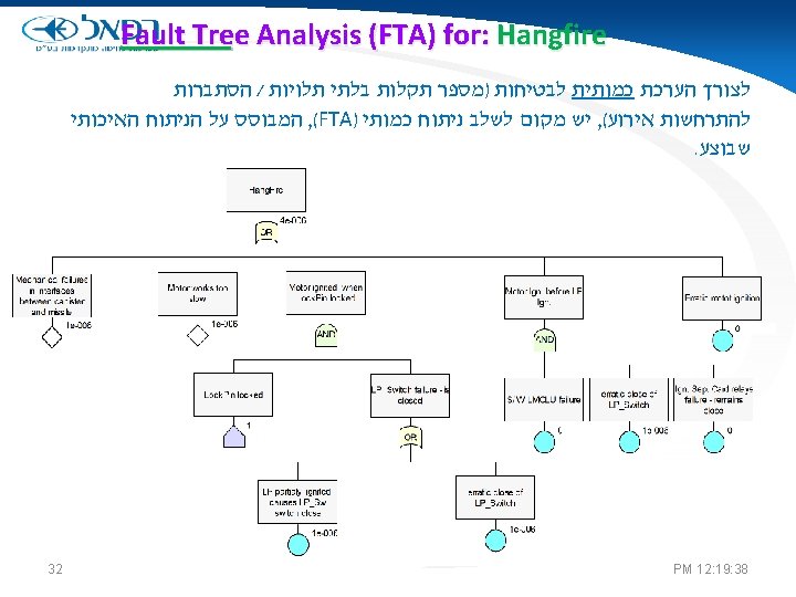
System Engineering Based Safety Analysis (SEBSA) 5. Refine high-level safety constraints into detailed safety requirements on components and scenarios for losses a) Identify potential inadequate control actions that could lead to a hazardous state b) Use identified inadequate control actions to refine system safety design constraints 6. Use results to create or improve system design 7. Use results to create FTA’s when quantity analysis needed. 29 PM 12: 19: 36
 5. Refine high-level safety constraints into detailed safety")
System Engineering Based Safety Analysis (SEBSA) 5. Refine high-level safety constraints into detailed safety requirements on components and scenarios for losses a) Identify potential inadequate control actions that could lead to a hazardous state b) Use identified inadequate control actions to refine system safety design constraints 6. Use results to create or improve system design 7. Use results to create FTA when needed. 31 PM 12: 19: 37
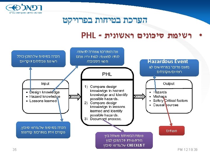
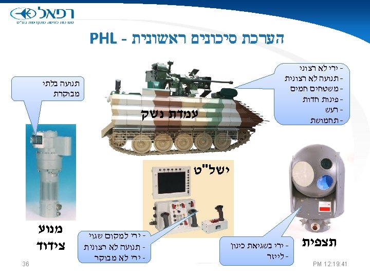

PHA - הערכת בטיחות בפרויקט גורמי שורש ברמת פירוט נמוכה יחסית 37 Initial Mishap Risk Index Final Mishap Risk Index PM 12: 19: 42
 • A new, more powerful accident causation model")
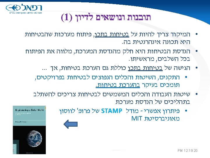
STAMP (System-Theoretic Accident Model and Processes) • A new, more powerful accident causation model • Based on systems theory, not reliability theory • Treats accidents as a dynamic control problem (vs. a failure problem) • Includes: – Entire socio-technical system (not just technical part) – Component interaction accidents – Software and system design errors – Human errors 39 PM 12: 19: 45

STAMP System Safety • Safety is an emergent system property : Ø It is NOT a component property Ø It can only be analyzed in the context of the whole • The primary safety problem in complex, softwareintensive systems is the lack of appropriate constraints on design The job of the system safety engineer is to: Ø Identify the constraints necessary to maintain safety Ø Ensure the system (including software) design enforces them 40 PM 12: 19: 46
 • Treat safety as a dynamic control problem")
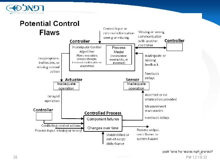
STAMP (System-Theoretic Accident Model and Processes) • Treat safety as a dynamic control problem rather than a component failure problem. • Events are the result of the inadequate control • Accidents occur when model of process is inconsistent with real state of process and controller provides inadequate control action 41 PM 12: 19: 47

STAMP Relationship Between Safety and Process Models Accidents occur when models do not match process and –Required control commands are not given –Incorrect (unsafe) ones are given –Correct commands given at wrong time (too early, too late) –Control action stops too soon or applied too long Explains software errors, human errors, component interaction accidents … 42 PM 12: 19: 47

STAMP Relationship Between Safety and Process Models How do they become inconsistent ? –Wrong from beginning –Missing or incorrect feedback –Not updated correctly –Time lags not accounted for Resulting in Uncontrolled disturbances Unhandled process states Inadvertently commanding system into a hazardous state Unhandled or incorrectly handled system component failures 43 PM 12: 19: 47
- Slides: 43