
SDN Traffic Engineering with Segment Routing The Next

- Slides: 25
SDN Traffic Engineering with Segment Routing The Next Evolution Cengiz Alaettinoglu
Traffic Engineering (TE) Minimize the worst link utilization • Alleviate traffic congestion • Better/longer use of equipment/port/fiber Route traffic around congested links • Put traffic on non-shortest paths Copyright © 2017 Packet Design. All rights reserved. 2
Evolution of Traffic Engineering Offline traffic engineering • Optimal, but not adaptive On-device traffic engineering • Adaptive, but not optimal Software defined networking • Best of both worlds, yet simpler; simplicity enabled by: • Segment routing • Push-based telemetry • SDN Traffic Engineering application Copyright © 2017 Packet Design. All rights reserved. 3
Offline Traffic Engineering Topology model Traffic demand matrix Optimization algorithm computes routes so that the worst link utilization is minimized • Linear programming Copyright © 2017 Packet Design. All rights reserved. 4
Pros/Cons of Offline Traffic Engineering Very good link utilization values Network model is hard to keep accurate Traffic demand matrix is hard to compute Optimization algorithm is very slow • Hours to days Can not adapt to failures Too many tunnels (N 2) Some paths may be surprisingly long Copyright © 2017 Packet Design. All rights reserved. 5
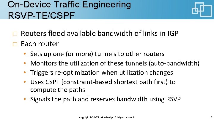
On-Device Traffic Engineering RSVP-TE/CSPF Routers flood available bandwidth of links in IGP Each router Sets up one (or more) tunnels to other routers Monitors the utilization of these tunnels (auto-bandwidth) Triggers re-optimization when utilization changes Uses CSPF (constraint-based shortest path first) to compute the paths • Signals the path and reserves bandwidth using RSVP • • Copyright © 2017 Packet Design. All rights reserved. 6
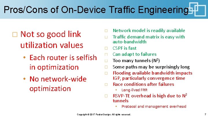
Pros/Cons of On-Device Traffic Engineering Not so good link utilization values • Each router is selfish in optimization • No network-wide optimization Network model is readily available Traffic demand matrix is easy with auto-bandwidth CSPF is fast Can adapt to failures Too many tunnels (N 2) Some paths may be surprisingly long Flooding available bandwidth impacts IGP, particularly convergence time Race conditions after failures • Long-lived FRR RSVP-TE overhead is high due to N 2 tunnels • Protocol and management overhead Copyright © 2017 Packet Design. All rights reserved. 7
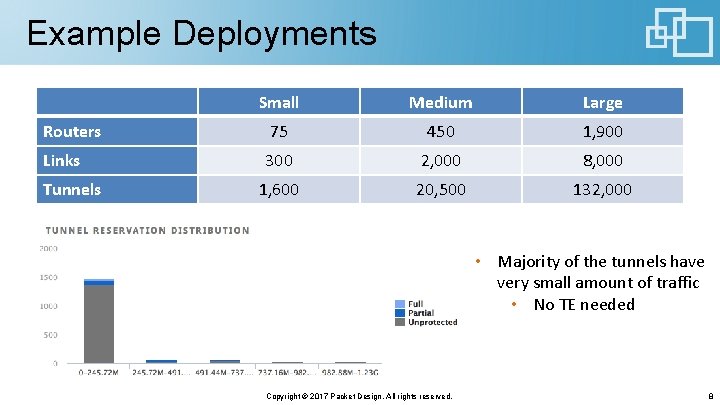
Example Deployments Small Medium Large Routers 75 450 1, 900 Links 300 2, 000 8, 000 1, 600 20, 500 132, 000 Tunnels • Majority of the tunnels have very small amount of traffic • No TE needed Copyright © 2017 Packet Design. All rights reserved. 8
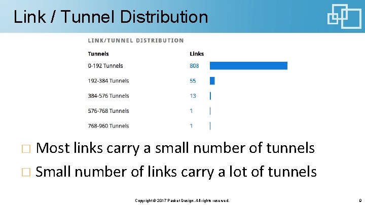
Link / Tunnel Distribution Most links carry a small number of tunnels Small number of links carry a lot of tunnels Copyright © 2017 Packet Design. All rights reserved. 9
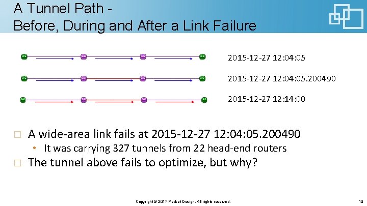
A Tunnel Path Before, During and After a Link Failure 2015 -12 -27 12: 04: 05. 200490 2015 -12 -27 12: 14: 00 A wide-area link fails at 2015 -12 -27 12: 04: 05. 200490 • It was carrying 327 tunnels from 22 head-end routers The tunnel above fails to optimize, but why? Copyright © 2017 Packet Design. All rights reserved. 10
Re-Optimization after Link Failure 22 head-end routers get a signal via RSVP-TE and try to re-optimize • Race to available bandwidth Each router optimizes for itself • It does not know what the other 21 routers need • It doesn’t even know there are other routers/tunnels interested in this bandwidth 9 tunnels fail to optimize • 5 head-end routers • The example tunnel is one of the unlucky ones This could have been avoided with network-wide optimization! Copyright © 2017 Packet Design. All rights reserved. 11
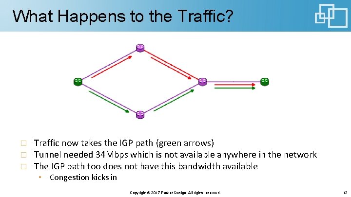
What Happens to the Traffic? Traffic now takes the IGP path (green arrows) Tunnel needed 34 Mbps which is not available anywhere in the network The IGP path too does not have this bandwidth available • Congestion kicks in Copyright © 2017 Packet Design. All rights reserved. 12
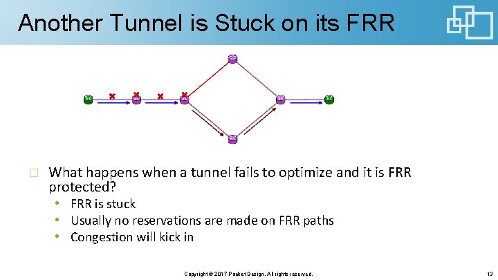
Another Tunnel is Stuck on its FRR What happens when a tunnel fails to optimize and it is FRR protected? • FRR is stuck • Usually no reservations are made on FRR paths • Congestion will kick in Copyright © 2017 Packet Design. All rights reserved. 13
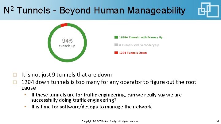
N 2 Tunnels - Beyond Human Manageability It is not just 9 tunnels that are down 1204 down tunnels is too many for any operator to figure out the root cause • If these tunnels are for traffic engineering, can we really say we are successfully doing traffic engineering? • It is time for software/devops to manage the network Copyright © 2017 Packet Design. All rights reserved. 14
AN SDN APPROACH Copyright © 2017 Packet Design. All rights reserved. 15
What Do We Really Need? Real-time model • Alleviate congestion, especially after a link failure Create as few tunnels as necessary • Very small signaling overhead • Very small IGP overhead • Do not want IGP dynamics due to available bandwidth changes Network-wide optimization Simple to deploy and operate Copyright © 2017 Packet Design. All rights reserved. 16
SDN Promises a Solution Segment routing (SR) replaces RSVP • Provides uncompromised functionality • Simple control plane with very low overhead Push-based telemetry for traffic matrices • YANG model based • Frees IGP SDN controller is part of the network control plane • Has real-time topology • Enables manipulating paths on the devices using standard south bound protocols Traffic Engineering becomes an SDN application • Optimizes paths network-wide • As few tunnels as necessary Copyright © 2017 Packet Design. All rights reserved. 17
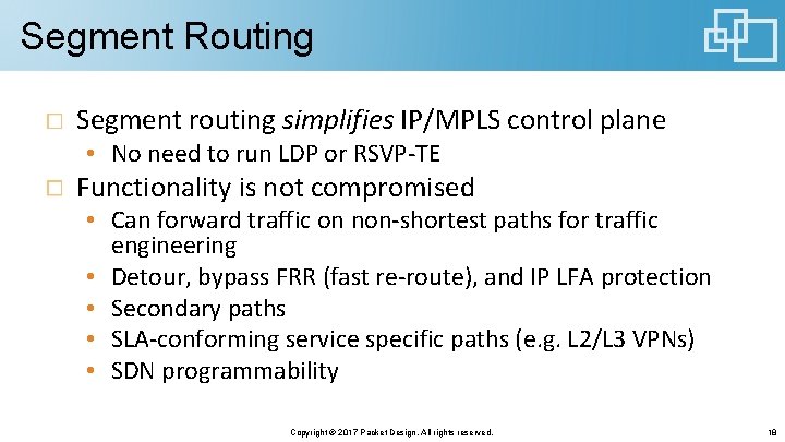
Segment Routing Segment routing simplifies IP/MPLS control plane • No need to run LDP or RSVP-TE Functionality is not compromised • Can forward traffic on non-shortest paths for traffic engineering • Detour, bypass FRR (fast re-route), and IP LFA protection • Secondary paths • SLA-conforming service specific paths (e. g. L 2/L 3 VPNs) • SDN programmability Copyright © 2017 Packet Design. All rights reserved. 18
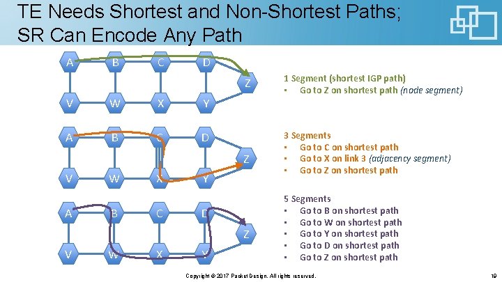
TE Needs Shortest and Non-Shortest Paths; SR Can Encode Any Path A B C D Z V W X Y A B C D Z V A W B X C Y D Z V W X Y 1 Segment (shortest IGP path) • Go to Z on shortest path (node segment) 3 Segments • Go to C on shortest path • Go to X on link 3 (adjacency segment) • Go to Z on shortest path 5 Segments • Go to B on shortest path • Go to W on shortest path • Go to Y on shortest path • Go to D on shortest path • Go to Z on shortest path Copyright © 2017 Packet Design. All rights reserved. 19
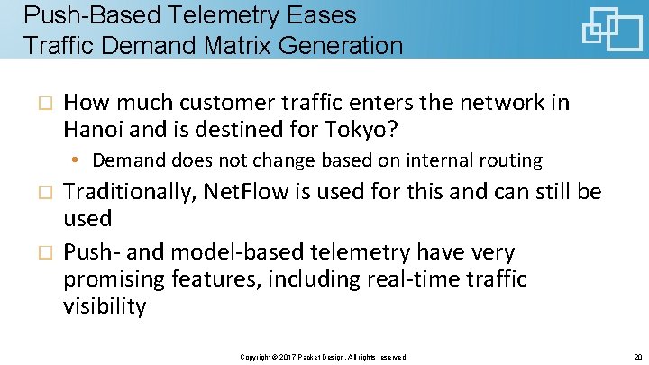
Push-Based Telemetry Eases Traffic Demand Matrix Generation How much customer traffic enters the network in Hanoi and is destined for Tokyo? • Demand does not change based on internal routing Traditionally, Net. Flow is used for this and can still be used Push- and model-based telemetry have very promising features, including real-time traffic visibility Copyright © 2017 Packet Design. All rights reserved. 20
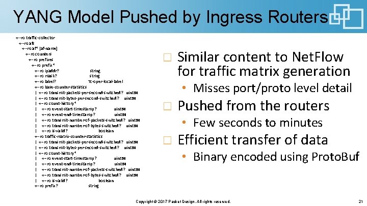
YANG Model Pushed by Ingress Routers +--ro traffic-collector +--ro afs +--ro af* [af-name] +--ro counters +--ro prefixes +--ro prefix* +--ro ipaddr? string +--ro mask? string +--ro label? Tc-oper-local-label +--ro base-counter-statistics | +--ro transmit-packets-per-second-switched? uint 64 | +--ro transmit-bytes-per-second-switched? uint 64 | +--ro count-history* | +--ro event-start-timestamp? uint 64 | +--ro event-end-timestamp? uint 64 | +--ro transmit-number-of-packets-switched? uint 64 | +--ro transmit-number-of-bytes-switched? uint 64 | +--ro is-valid? boolean +--ro traffic-matrix-counter-statistics | +--ro transmit-packets-per-second-switched? uint 64 | +--ro transmit-bytes-per-second-switched? uint 64 | +--ro count-history* | +--ro event-start-timestamp? uint 64 | +--ro event-end-timestamp? uint 64 | +--ro transmit-number-of-packets-switched? uint 64 | +--ro transmit-number-of-bytes-switched? uint 64 | +--ro is-valid? boolean +--ro prefix? string Similar content to Net. Flow for traffic matrix generation • Misses port/proto level detail Pushed from the routers • Few seconds to minutes Efficient transfer of data • Binary encoded using Proto. Buf Copyright © 2017 Packet Design. All rights reserved. 21
Traffic Engineering as an SDN App. SDN application manages traffic demand • Current as well as future reservations • IGP does not have to signal available bandwidth • Push-based telemetry or Net. Flow-based matrices can be generated SDN application computes paths and allocates bandwidth • Centralization yields network-wide resource optimization • Creates the fewest tunnels necessary SDN application adapts to failures and repairs • SDN controller provides real-time topology view • No race conditions after failures and repairs Segment routing can be used for network simplification • SDN controller makes this an abstraction for the application • RSVP-TE can still be used where SR is not available Copyright © 2017 Packet Design. All rights reserved. 22
Reducing the N 2 Tunnels Only generates tunnels for traffic going over congested links • Tunnels no longer need to be configured a priori at the routers • Only create them if they will have a positive impact • Special case: • Under normal conditions don’t generate any tunnels • Under failure conditions generate enough to alleviate congestion Do not create tunnels when IGP path satisfies the constraints Easy to implement in software with a global view, but hard to do one device at a time Copyright © 2017 Packet Design. All rights reserved. 23
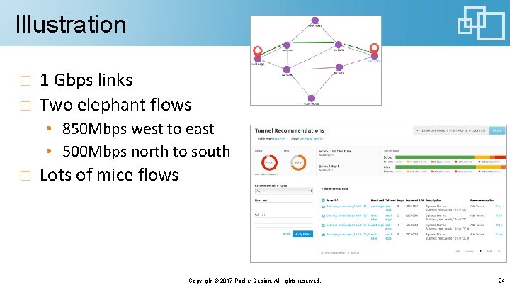
Illustration 1 Gbps links Two elephant flows • 850 Mbps west to east • 500 Mbps north to south Lots of mice flows Copyright © 2017 Packet Design. All rights reserved. 24
Concluding Remarks SDN simplifies running a traffic engineered network • Application is the SDN revolution SDN application needs enablers from the infrastructure • • Controller Segment routing (or RSVP-TE when not available) Push-based telemetry NETCONF/YANG, PCEP, and other southbound protocols Copyright © 2017 Packet Design. All rights reserved. 25