SDLC Clearly the SDLC requires significant time human

 แสดงถงสงทระบบใหมจะตองทำ ประกอบดวย - Entity-Relationship Diagrams √ -")

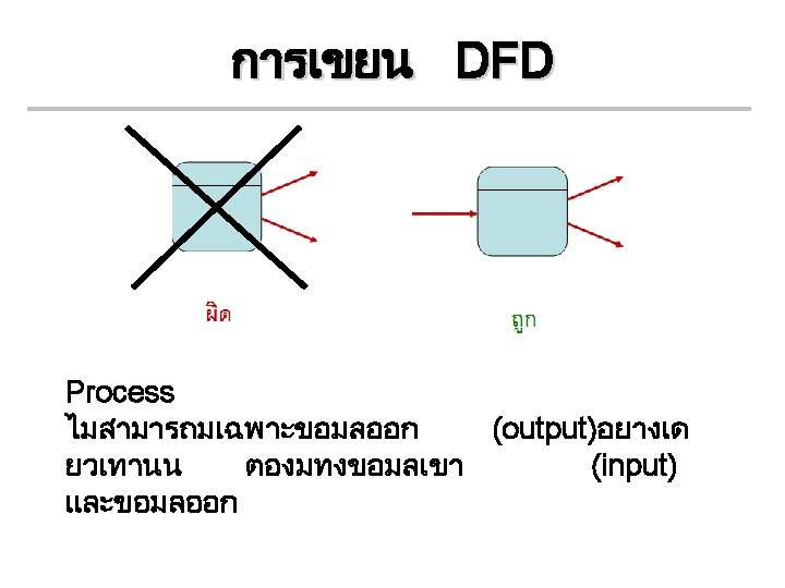
 • Graphical system model that shows all main")
 DFD is used to link between initial business")
 • Context Diagram is DFD that summarizes all processing")


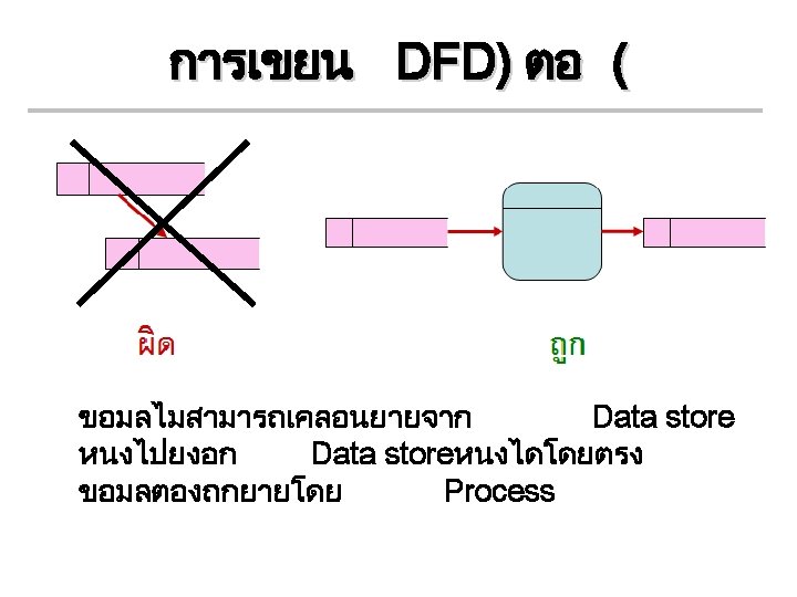
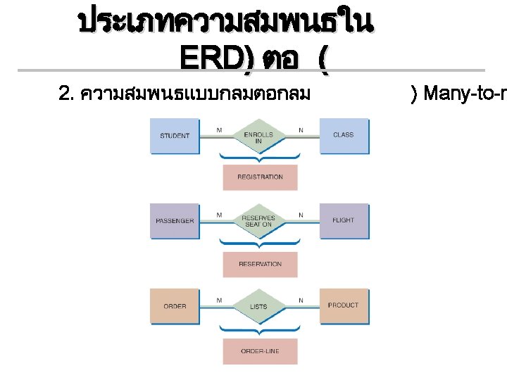
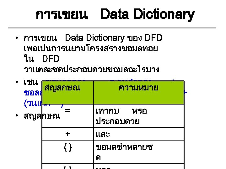
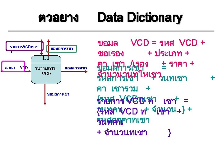
 ตอ ( 1 Entity 1 Input A General Process AAA 2 Data")


- Slides: 40
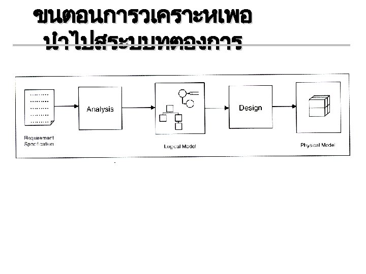
พจารณา SDLC • Clearly, the SDLC requires significant time, human resources and technical resources to perform well. • The main steps in SDLC can be presented as follows: (1) Systems Planning (project requirements summary, project team description, preliminary work schedule, service area demographic analysis) (2) Systems Analysis (E-R diagram, Data Flow Diagrams, high-level functional description) (3) Systems Design (RDBM, Data Dictionary, identification/description of database objects, Web site map) (4) Systems Implementation (Access database, Web site content, elementary test plan)
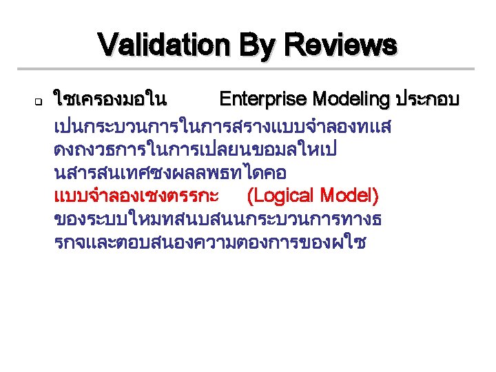
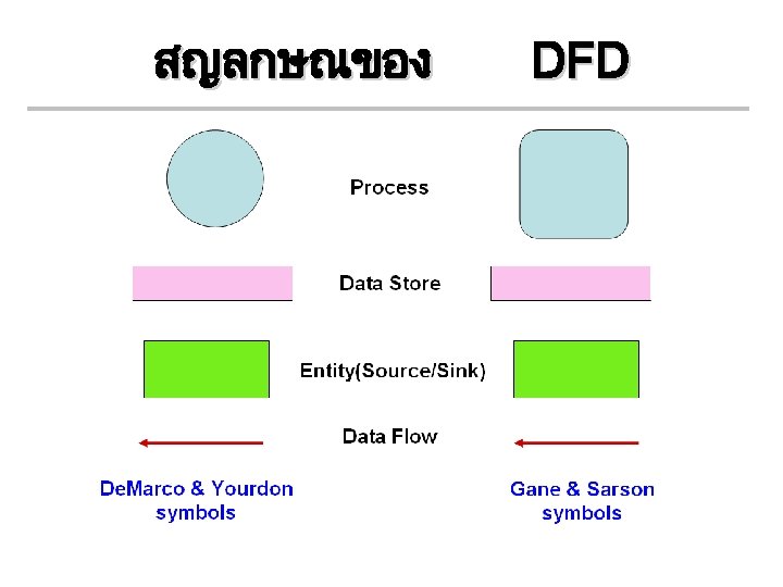
Validation By Reviews • แบบจำลองเชงตรรกะ (Logical Model) แสดงถงสงทระบบใหมจะตองทำ ประกอบดวย - Entity-Relationship Diagrams √ - Data Flow Diagrams √ - Data Dictionary - Process Description
Data Flow Diagram: DFD (ตอ ) • Graphical system model that shows all main requirements for an IS in one diagram Inputs/outputs Processes Data storage • DFD integrates processing triggered by events (event table) with the data entities modeled by ERD
Data Flow Diagram: DFD (ตอ ) DFD is used to link between initial business analysis, E-R diagrams and relational database models
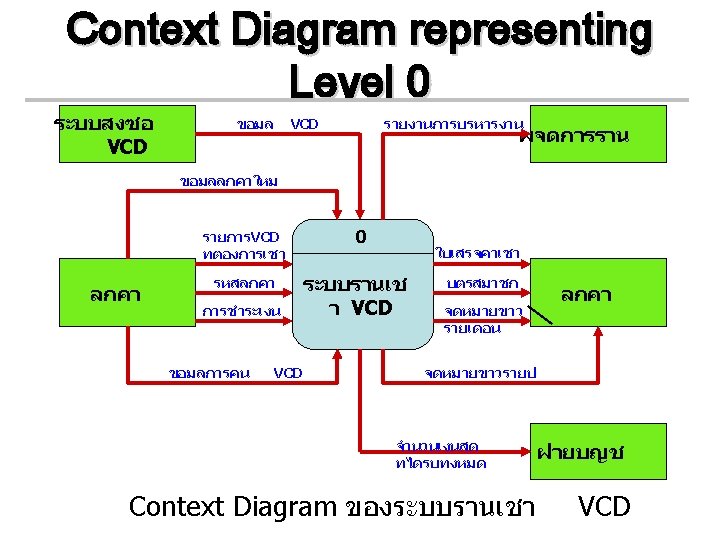
DFD: Context Diagram (ตอ ) • Context Diagram is DFD that summarizes all processing activity for the system or subsystem • Highest level (most abstract) view of system • Shows system boundaries • System scope is represented by a single process, external agents, and all data flows into and out of the system • แสดงหมายเลข Process เปนหมายเลข 0
ตวอยาง Entity 1 Entity 2 Context Diagram Input A 0 Input B System Name Output C Context Diagram Entity 3
ตวอยาง Context Diagram
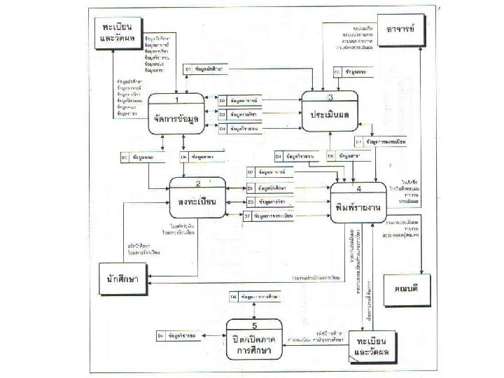
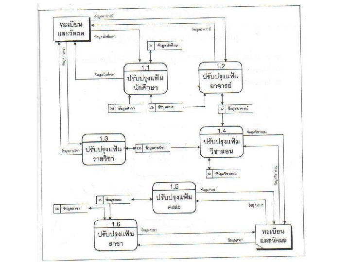
ตวอยาง DFD) ตอ ( 1 Entity 1 Input A General Process AAA 2 Data flow B Data flow C General Process BBB Record E Record A D 1 Data store 1 D 2 Data store 2 Record A 3 Entity 2 Input B General Process CCC Output C Record E 4 Data flow D General Process DDD Entity 3
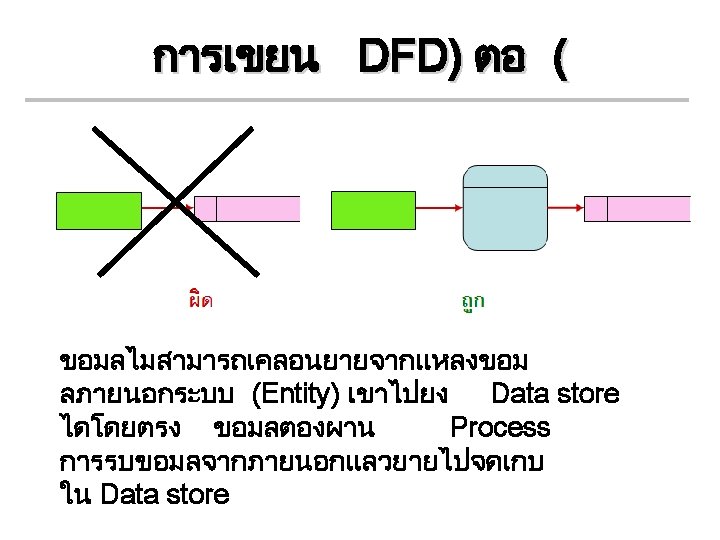
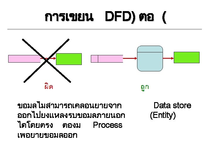
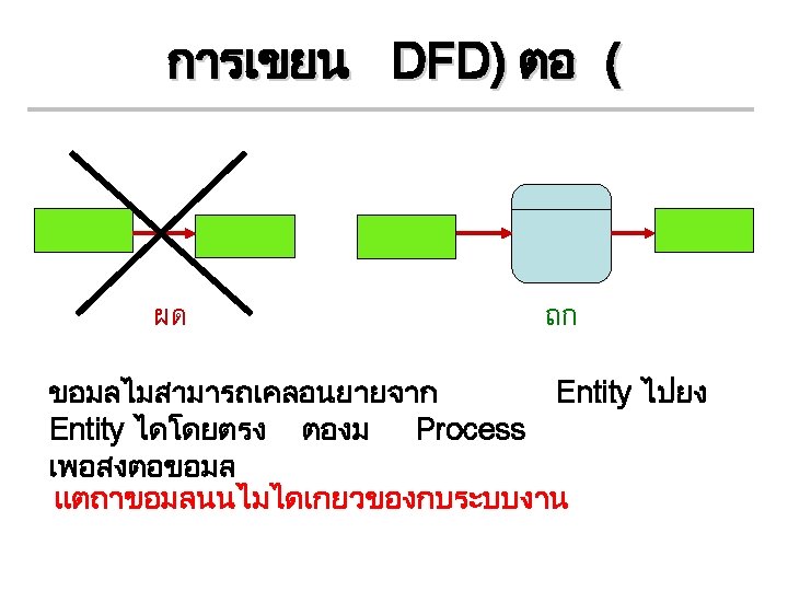
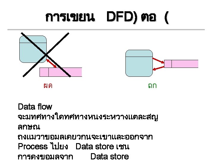
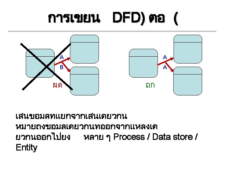
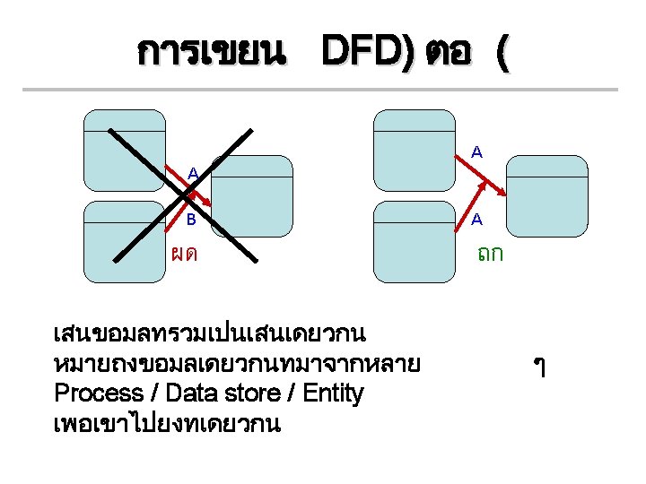
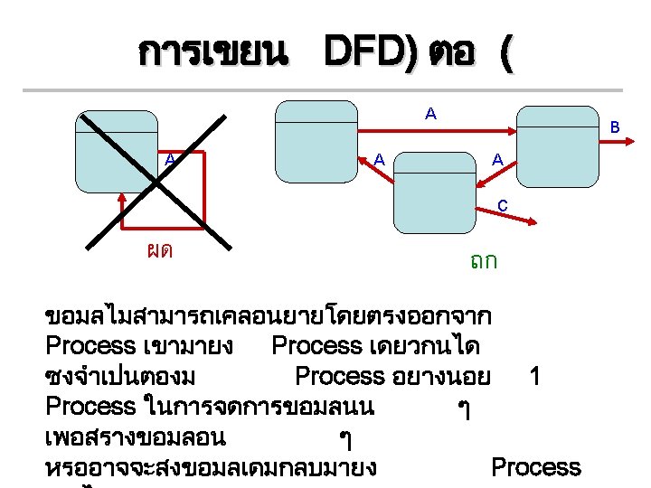
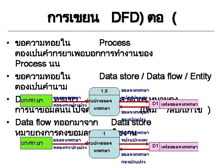
Confusion of DFD
Context Diagram without representing Level
Context Diagram without representing Level (ตอ ( *** DFD Level 0 ***
Context Diagram representing Level 0 (ตอ ( DFD level 1