Screenshots of Mentor Schematic Capture Software TAMU Group


- Slides: 16
Screenshots of Mentor Schematic Capture Software TAMU Group August 2014 J. Gilmore 1
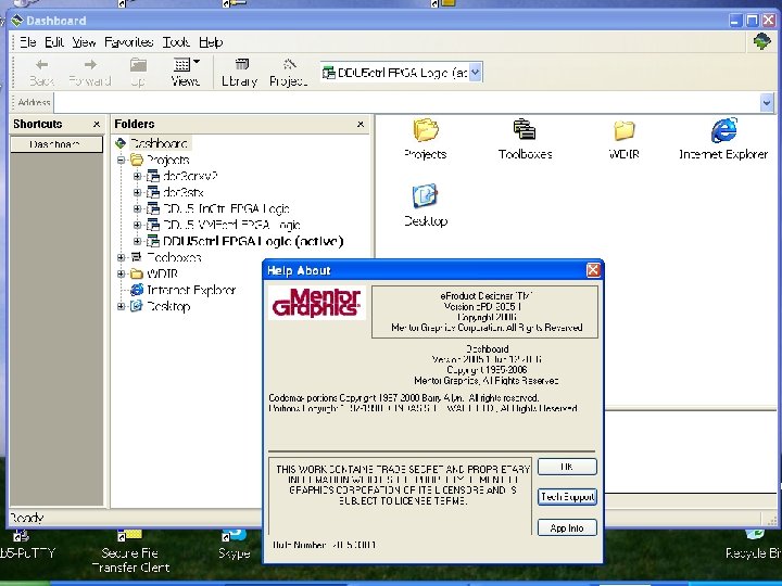
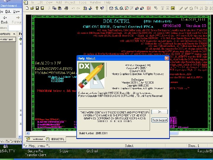
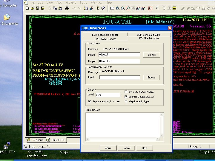
What is it called, how to use it? • “e. Product Designer” – TAMU has a license server for this… • Accessed with the MGLS_LICENSE_FILE Environment Variable: license 2. cse. tamu. edu: 1717; 1717@license 2. cse. tamu. edu • e. PD Dashboard is the launch point – Where libraries and projects are organized • You can also edit text files by hand… viewlogic. ini? – Select the “active” project and go to its Schematics folder • From here we initiate the schematic tool – Now called “e. PD Dx. Designer” • Used to be called Workview Viewlogic – Double-click on top-level sch file to begin • Can also edit symbols inside this program – Use “EDIF Netlist Writer” tool to generate. edn file for ISE • Run this on the top-level schematic after saving all files • Make sure to use the options shown here on the slides • Check the file “mgnwrite. err” for errors (should be 0 KB size)
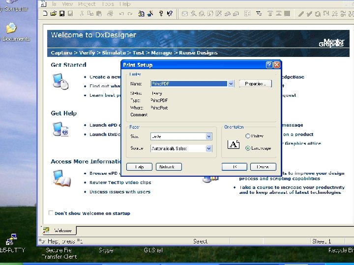
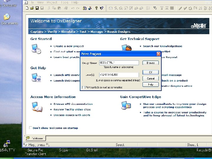
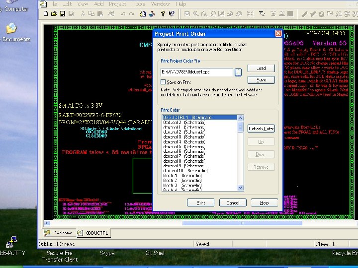
How To Print the Project • Make a PDF print of all the project sheets – First close all design files – Go to “Print Setup” • Select “Landscape” and choose your PDF printer • Next choose “Print Project” – Browse to select the top level of your design – Choose Level(s): “XILINX MXILINX” • Then click OK • After ~2 minutes you’ll get the Project Print Order pop-up – Browse to find the correct. ppo file in the WV/D 785 folder • Un-select the “Save on Print” button, then click “Load” – The list of sheets should appear in proper order • Click once on the top item to highlight it, then click “Print”
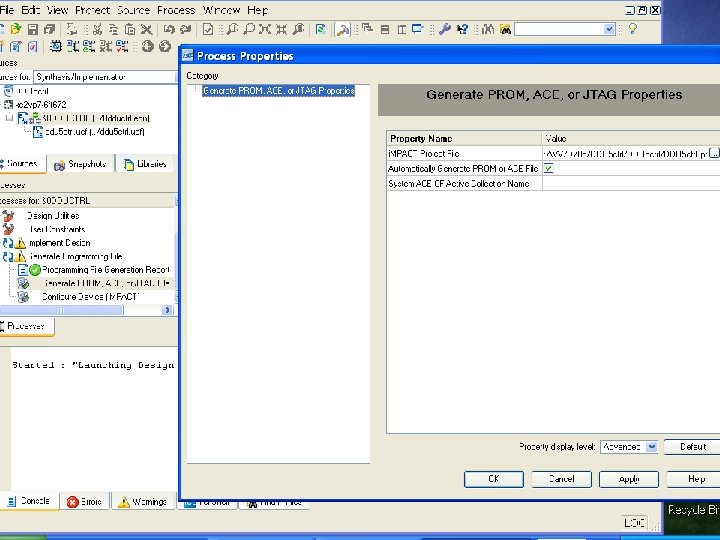
Compiling with ISE 9. 2 • Startup ISE 9. 2 i from the desktop – Open the correct project to compile – Right-click on “Generate Programming File” to open “Properties” • Choose “Configuration Options” • Set User. ID Code to “ 0 x. CF 056 A 02” or similar for the version code • Click “Apply” then “OK” – Click the “+” beside “Generate Programming File” – Right-click on “Generate PROM, ACE or JTAG file” to open “Properties” • Select the “Automatically Generate PROM or ACE File” button • Verify the “IMACT Project File” is the correct. ipf file • Click “Apply” then “OK” • Double-click on “Generate PROM, ACE or JTAG file” to begin compiling – After a few minutes it should be done • Check that routing was completed and all constraints were met – The new. mcs file(s) should be in the ISE project folder
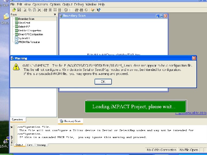
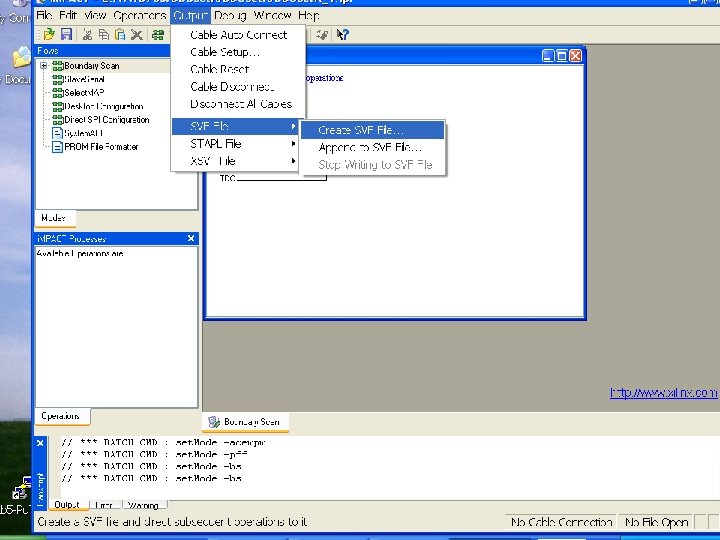
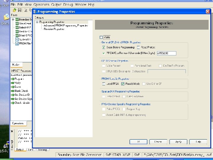
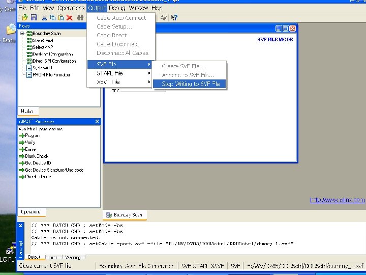
Creating SVF Files with IMPACT • Startup IMPACT from the desktop – Open the correct. ipf project file under “File -> Open Project” • Note the files with _0 and _1 will use corresponding. mcs files – Choose “No” when prompted to save – Ignore any warning about an invalid configuration file • Select “Output -> SVF File -> Create SVF File” – Select the folder and file where you want the SVF saved • Right-click on the PROM icon and select “Program” – An options window will pop up • Un-select “Verify” and select “Erase Before Programming” • Select “Parallel Mode” and also “PROM/Cool Runner-II” user code – Choose a good code to serve as your firmware version tag – Click on “Apply” and “OK”… after a few seconds it should be done • Select “Output -> SVF File -> Stop Writing to SVF File” – The new. svf file should be in the ISE project folder – Quit the program, and do not save • Restart the program if additional SVF files are needed ** Run “dos 2 unix” on the SVF files to make them useable! **