
SCM PREAMP SENSOR Fabrication Readiness Review P Leroy

SCM PREAMP & SENSOR Fabrication Readiness Review P. Leroy
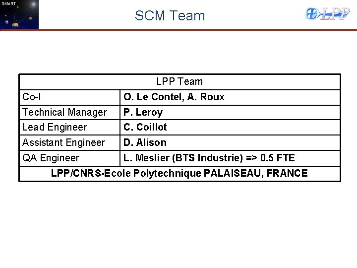
SCM Team LPP Team Co-I O. Le Contel, A. Roux Technical Manager Lead Engineer P. Leroy C. Coillot Assistant Engineer D. Alison QA Engineer L. Meslier (BTS Industrie) => 0. 5 FTE LPP/CNRS-Ecole Polytechnique PALAISEAU, FRANCE
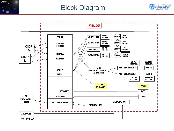
Block Diagram
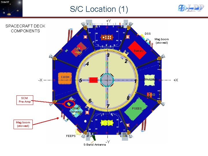
S/C Location (1) +Y SPACECRAFT DECK COMPONENTS DSS Mag boom (stowed) RF xnpdr 3 2 4 -X SCM Pre-Amp C&DH Battery 5 DPU 1 USO 8 6 7 Star Sensors Mag boom (stowed) FEEPS -Y S-Band Antenna Navigator PSEES +X
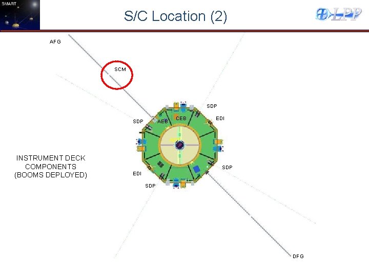
S/C Location (2) AFG SCM SDP AEB CEB EDI ADP INSTRUMENT DECK COMPONENTS (BOOMS DEPLOYED) SDP EDI SDP DFG
SCM PREAMP
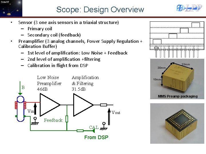
Scope: Design Overview • • Sensor (3 one axis sensors in a triaxial structure) – Primary coil – Secondary coil (feedback) Preamplifier (3 analog channels, Power Supply Regulation + Calibration Buffer) – 1 st level of amplification: Low Noise + Feedback – 2 nd level of amplification +filtering – Calibration in flight from DSP Low Noise Preamplifier 46 d. B B Amplification & Filtering 31. 5 d. B 33 mm 30 mm 18 mm MMS Preamp packaging Vin Vout Feedback CAL From DSP
Action items since last review (CDR) • Gains have been adjusted to meet the resolution requirement • The preamp has been tuned with the EM 4 sensors (4 mm ferrite cores). The sensitivity requirements are also satisfied now • Radiation Qualification of the commercial JFET finished, LAT also. Screening end 16 OCT 2010
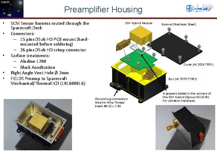
Preamplifier Housing • • • SCM Sensor harness routed through the Spacecraft Deck Connectors: – 15 pins DSub HD PCB mount (hardmounted before soldering) – 26 pins DSub HD crimp connector Surface treatments: – Alodine 1200 – Black Anodization Right Angle Vent Hole Ø 2 mm FIELDS Preamp to Spacecraft Mechanical/Thermal ICD (101600016) 3 D+ Hybrid Module Screws (Stainless Steel) Cover (Al 2024 T 851) Box (Al 7075 T 7351) Ground lug connection Hole for Wire Thread Insert #8 -32 x 1. 5 d 4 spacers added in the corners of the 3 D+ Hybrid (Epoxy+EC 2216) for vibration hardness
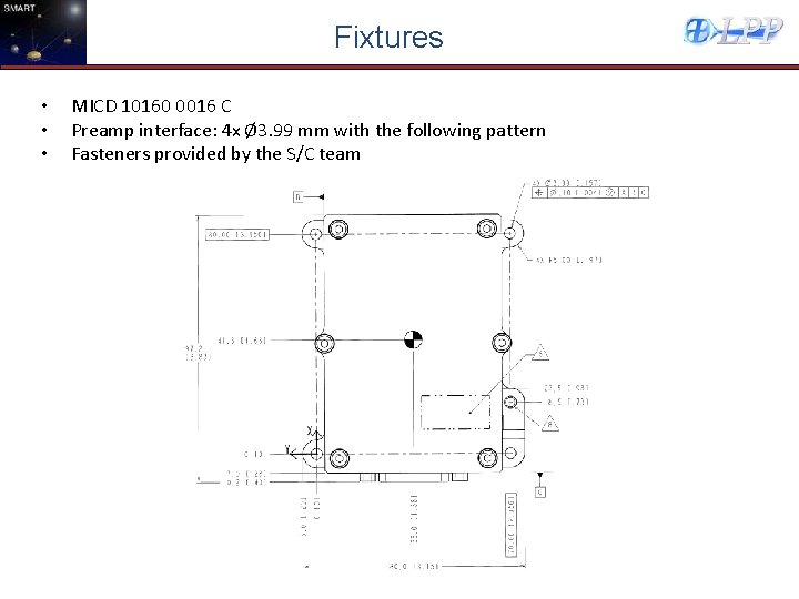
Fixtures • • • MICD 10160 0016 C Preamp interface: 4 x Ø 3. 99 mm with the following pattern Fasteners provided by the S/C team
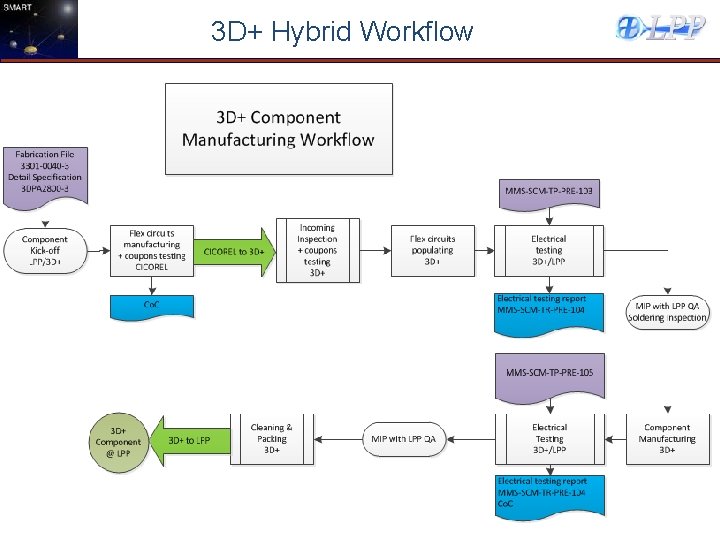
3 D+ Hybrid Workflow
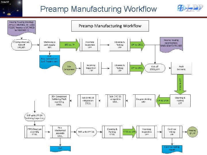
Preamp Manufacturing Workflow
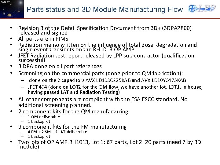
Parts status and 3 D Module Manufacturing Flow • Revision 3 of the Detail Specification Document from 3 D+ (3 DPA 2800) released and signed • All parts are in PIMS • Radiation memo written on the influence of total dose degradation and single event transients on the RH 1013 OP AMP • JFET Radiation test report released by LPP sub-contractor (qualification successful) • 3 DPA done on all part references • Screening on the commercial parts (done prior to QM fabrication): – done on the 2 capacitors AVX LD 103 C 225 KAB and AVX LD 10 YC 475 KAB – JFET 404 (done on LOT 2 for the QM flow, we have another lot, LOT 1, in house, having passed LAT and Radiation Testing) • All other components are compliant with the ESA ESCC standard. No additional screening planned. • 2 component kits for the QM manufacturing – 1 QM deliverable – 1 backup kit • 9 component kits for the FM manufacturing – 4 FM + 2 SM + 2 LAT deliverable – 1 backup kit • Two lots of OP AMP RH 1013, Lot 1: 67 parts, Lot 2: 20 parts (need 7 by 3 D module).
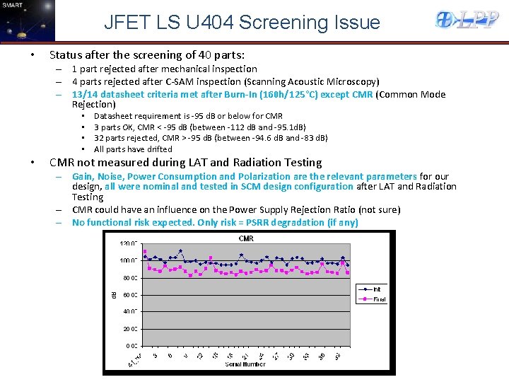
JFET LS U 404 Screening Issue • Status after the screening of 40 parts: – 1 part rejected after mechanical inspection – 4 parts rejected after C-SAM inspection (Scanning Acoustic Microscopy) – 13/14 datasheet criteria met after Burn-In (160 h/125°C) except CMR (Common Mode Rejection) • • • Datasheet requirement is -95 d. B or below for CMR 3 parts OK, CMR < -95 d. B (between -112 d. B and -95. 1 d. B) 32 parts rejected, CMR > -95 d. B (between -94. 6 d. B and -83 d. B) All parts have drifted CMR not measured during LAT and Radiation Testing – Gain, Noise, Power Consumption and Polarization are the relevant parameters for our design, all were nominal and tested in SCM design configuration after LAT and Radiation Testing – CMR could have an influence on the Power Supply Rejection Ratio (not sure) – No functional risk expected. Only risk = PSRR degradation (if any)
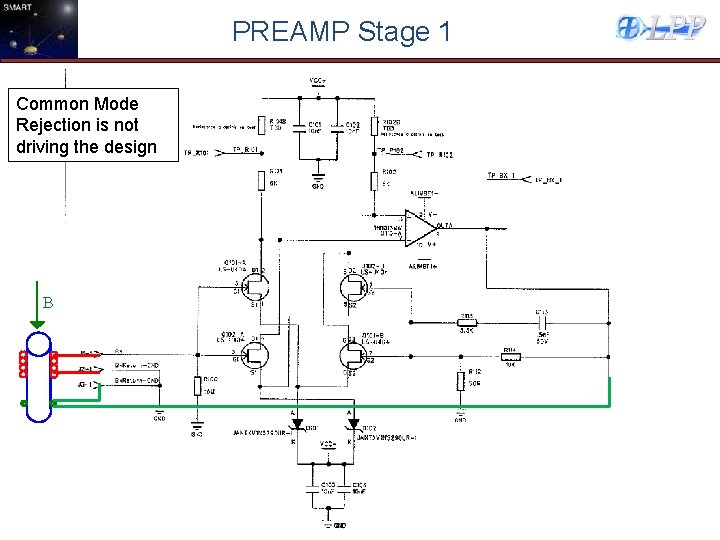
PREAMP Stage 1 Common Mode Rejection is not driving the design B
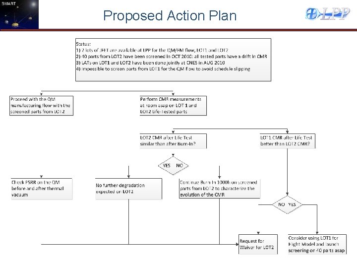
Proposed Action Plan
Schedule
SCM SENSOR
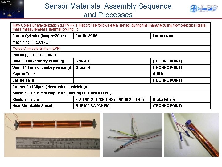
Sensor Materials, Assembly Sequence and Processes Raw Cores Characterization (LPP) => 1 Report File follows each sensor during the manufacturing flow (electrical tests, mass measurements, thermal cycling…) Ferrite Cylinder (length=20 cm) Ferrite 3 C 95 Ferroxcube Wire, 63μm (primary winding) Grade 1 (TECHNOPOINT) Wire, 140μm (secondary winding) Grade H (TECHNOPOINT) Machining (PRECINET) Cores Characterization (LPP) Winding (TECHNOPOINT) Kapton Tape (UNH) Lacing Tape (TECHNOPOINT) Copper Foil 30μm (electrostatic shielding) Shielded Triplet Splicing and Soldering (TECHNOPOINT) Shielded Triplet F A 3901 -2 -3 -28 HG-B 2 (3901 -002 -66 -B 2) Draka Fileca Heat Shrinkable Sheath RNF 100 RAYCHEM (TECHNOPOINT)
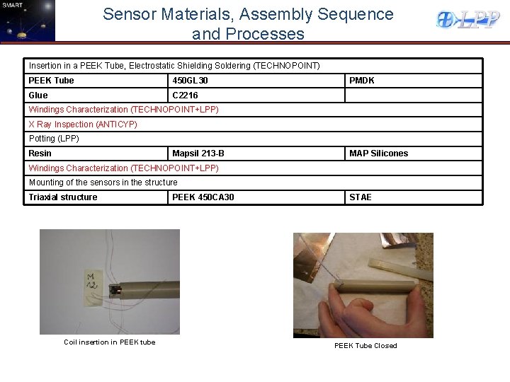
Sensor Materials, Assembly Sequence and Processes Insertion in a PEEK Tube, Electrostatic Shielding Soldering (TECHNOPOINT) PEEK Tube 450 GL 30 Glue C 2216 PMDK Windings Characterization (TECHNOPOINT+LPP) X Ray Inspection (ANTICYP) Potting (LPP) Resin Mapsil 213 -B MAP Silicones Windings Characterization (TECHNOPOINT+LPP) Mounting of the sensors in the structure Triaxial structure Coil insertion in PEEK tube PEEK 450 CA 30 STAE PEEK Tube Closed
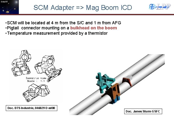
SCM Adapter => Mag Boom ICD • SCM will be located at 4 m from the S/C and 1 m from AFG • Pigtail connector mounting on a bulkhead on the boom • Temperature measurement provided by a thermistor Doc. BTS Industrie, 046829 D ed 00 Doc. James Sturm GSFC
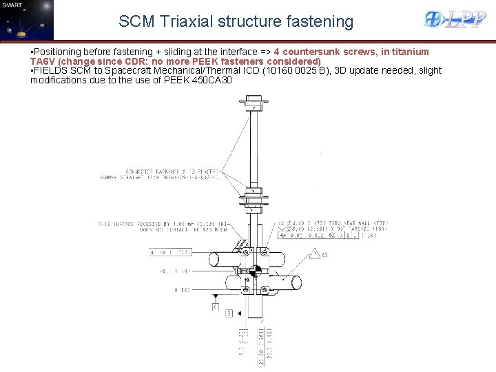
SCM Triaxial structure fastening • Positioning before fastening + sliding at the interface => 4 countersunk screws, in titanium TA 6 V (change since CDR: no more PEEK fasteners considered) • FIELDS SCM to Spacecraft Mechanical/Thermal ICD (10160 0025 B), 3 D update needed, slight modifications due to the use of PEEK 450 CA 30
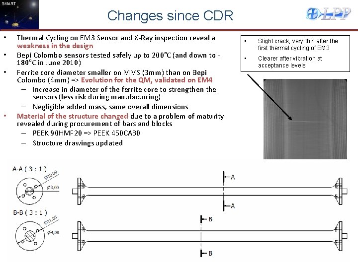
Changes since CDR • • Thermal Cycling on EM 3 Sensor and X-Ray inspection reveal a weakness in the design Bepi Colombo sensors tested safely up to 200°C (and down to 180°C in June 2010) Ferrite core diameter smaller on MMS (3 mm) than on Bepi Colombo (4 mm) => Evolution for the QM, validated on EM 4 – Increase in diameter of the ferrite core to strengthen the sensors (less risk during manufacturing) – Negligible added mass, same overall dimensions Material of the structure changed due to a problem of maturity revealed during procurement of bars and blocks – PEEK 90 HMF 20 => PEEK 450 CA 30 – Structure drawings updated • Slight crack, very thin after the first thermal cycling of EM 3 • Clearer after vibration at acceptance levels
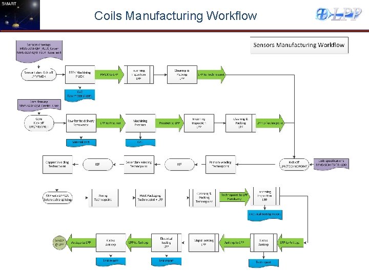
Coils Manufacturing Workflow
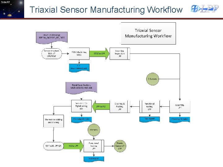
Triaxial Sensor Manufacturing Workflow
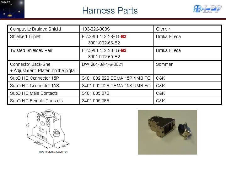
Harness Parts Composite Braided Shield 103 -026 -008 S Glenair Shielded Triplet F A 3901 -2 -3 -28 HG-B 2 3901 -002 -66 -B 2 Draka-Fileca Twisted Shielded Pair F A 3901 -2 -2 -28 HG-B 2 3901 -002 -65 -B 2 Draka-Fileca Connector Back-Shell + Adjustment Platen on the pigtail DW 264 -09 -1 -6 -0021 Sommer Sub. D HD Connector 15 P 3401 002 02 B DEMA 15 P NMB FO C&K Sub. D HD Connector 15 S 3401 002 02 B DEMA 15 S NMB FO C&K Sub. D HD Male Contacts 3401 005 07 B C&K Sub. D HD Female Contacts 3401 005 08 B C&K
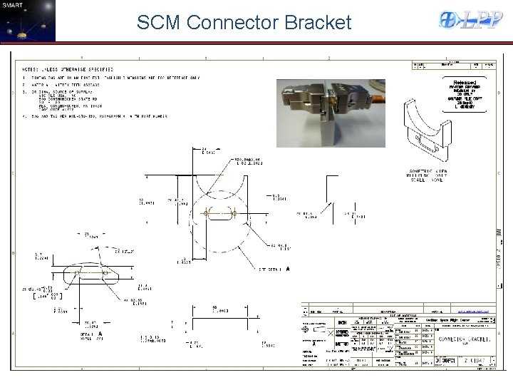
SCM Connector Bracket
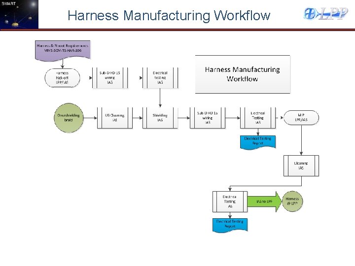
Harness Manufacturing Workflow
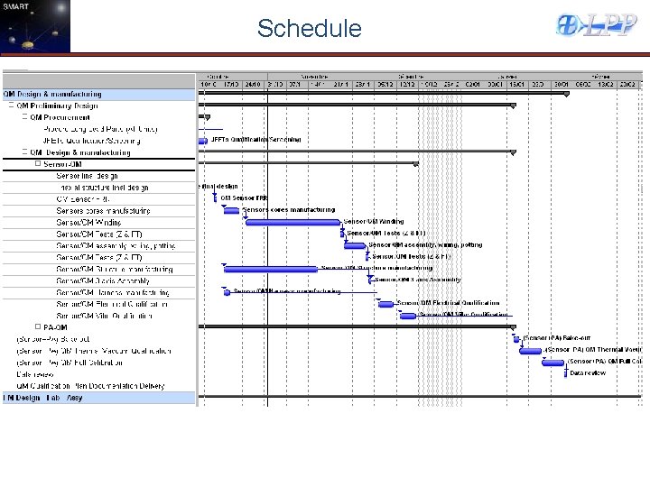
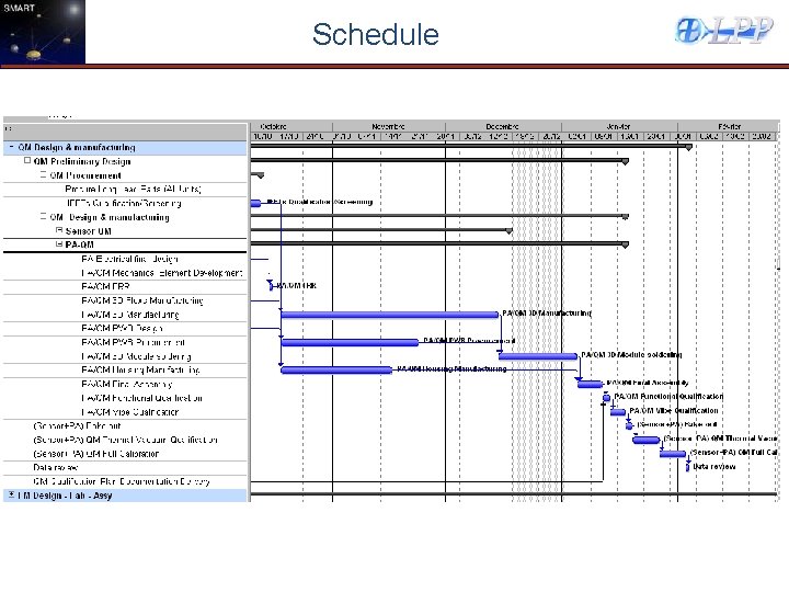
Schedule
QA Activites, Qualification, Calibration
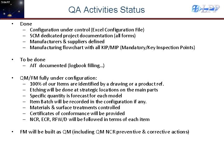
QA Activities Status • Done – Configuration under control (Excel Configuration File) – SCM dedicated project documentation (all forms) – Manufacturers & suppliers defined – Manufacturing flowchart with all KIP/MIP (Mandatory/Key Inspection Points) • To be done – AIT documented (logbook filling…) • QM/FM fully under configuration: – 100% of our Items are identified by a drawing or a product ref. – Etching will be done at strategic locations on the main parts – Specific quantity is forecast for each model – Item Batch will be recorded in the configuration if any. – Materials & surface treatments controlled – Certificates of conformance will be provided – NCR, ECR, RFW/D will be followed in terms of each item • FM will be built as QM (including QM NCR preventive & corrective actions)
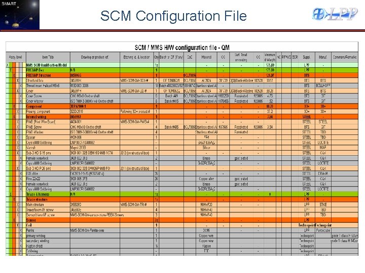
SCM Configuration File
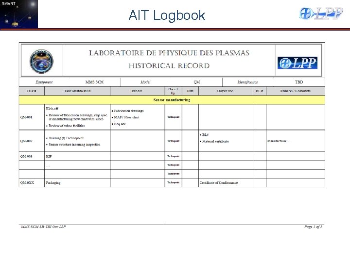
AIT Logbook
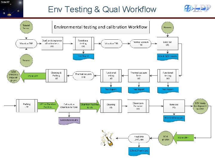
Env Testing & Qual Workflow
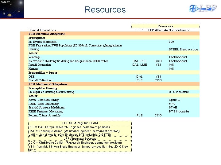
Resources Special Operations SCM Electrical Subsystems Preamplifier 3 D Hybrid Fabrication PWB Fabrication, PWB Populating (3 D Hybrid, Connectors), Integration in Housing Sensor Windings Electrostatic Shielding Soldering and Integration in PEEK Tubes Pigtail Connexion Harness Preamplifier + Sensor GSE Overall Calibration SCM Mechanical Subsystems Preamplifier Housing Manufacturing Sensor Ferrite Cores Machining PEEK Tubes Machining Triaxial Structure Machining PEEK Fasteners Machining Potting, Triaxis Assembly LPP SCM Regular TEAM PLE = Paul Leroy (Research Engineer, permanent position) DAL = Dominique Alison (Assistant Engineer, permanent position) LME = Lionel Meslier (QA Engineer, BTS Industrie, 0, 5 FTE) LPP Alternate Sources CCO = Christophe Coillot (Research Engineer, permanent position) YSI = Yannick Simon (Study Engineer, temporary position Sep 2010 -Dec 2011) LPP DAL, PLE DAL, LME DAL PLE Resources LPP Alternate Subcontractor 3 D+ CCO YSI CCO STEEL Electronique Technopoint IAS BTS Industrie Optik-C MPC STAE BTS Industrie

SCM PREAMP & SENSOR Fabrication Readiness Review P. Leroy
- Slides: 36