Schematic to Pictorial Page A 4 schematic to


 circuit for this schematic. Now move")
. You will notice that")


- Slides: 52
Schematic to Pictorial Page A 4 schematic to Page A 4 a pictorial
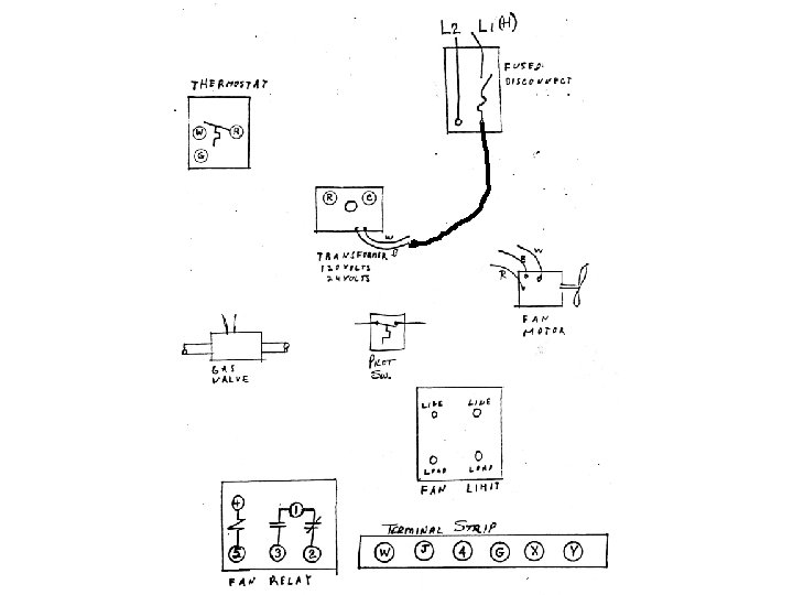
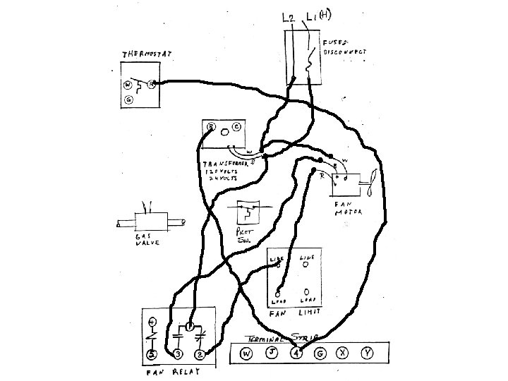
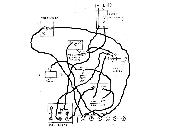
Take page A 4 and A 4 a out of your ‘Student Handout Packet’ and lay them side by side. You will follow the schematic on page A 4 and draw wires, using your pencil, on page A 4 a to complete the circuit. Absolutely no pens allowed.
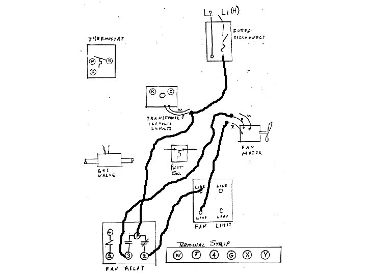
Start on page A 4 at the incoming power. Page A 4 shows the black wire going to the transformer primary wire and it will be the black wire on the primary. So go to page A 4 a and draw a wire from the fused disconnect to the transformer primary. See next 2 slides for help and to check your work.
W R
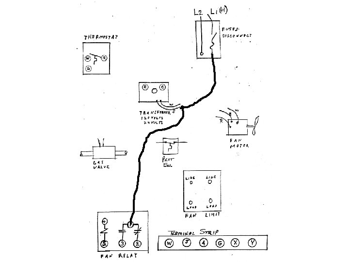
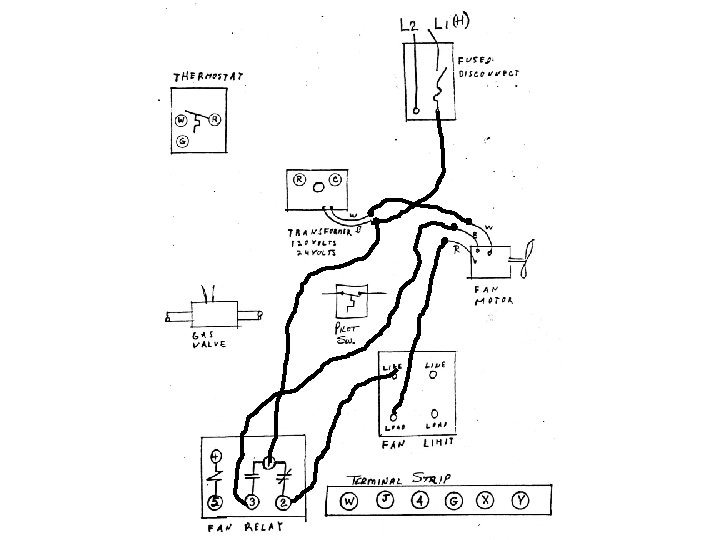
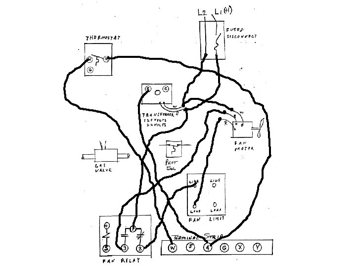
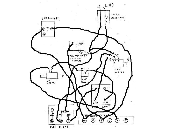
Continue from this junction point at the transformer and go to terminal 1 of the fan relay. See next 2 slides for help and to check your work.
W R
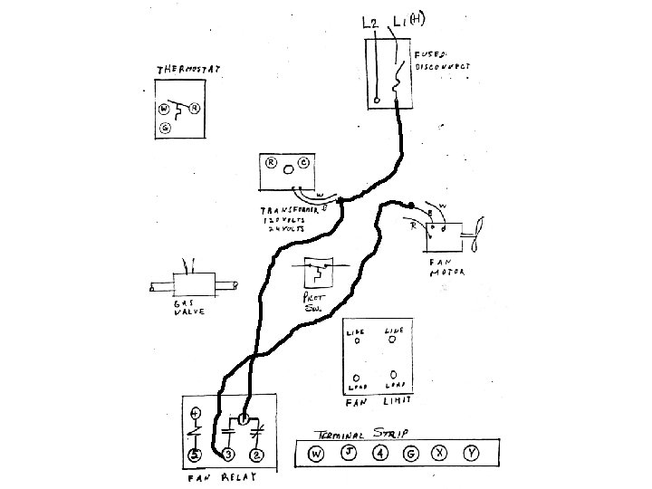
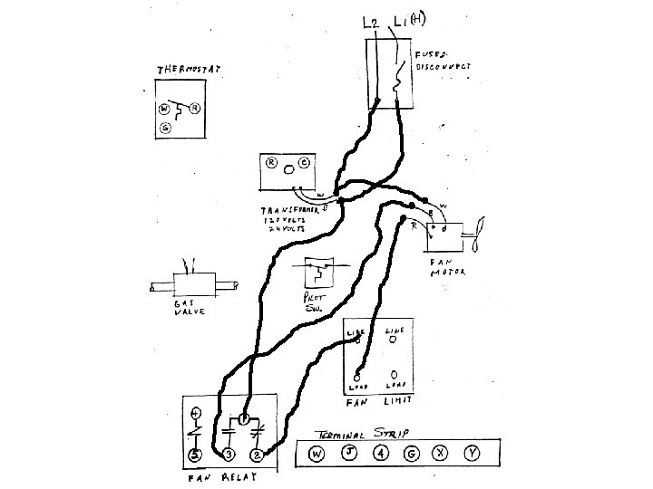
Continue from terminal 3 of the fan relay and go to the motors ‘B’ wire. See next 2 slides for help and to check your work.
W R
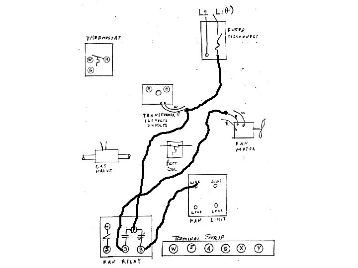
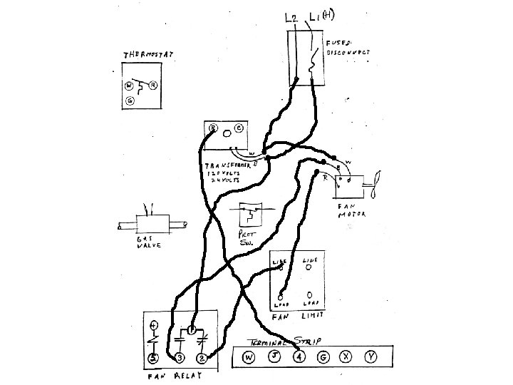
Now go back to terminal 2 of the fan relay and go to the fan switch. You will notice that the fan switch is marked ‘LINE’ and ‘LOAD. ’ You will bring power to the ‘LINE’ terminal. See next 2 slides for help and to check your work.
W R
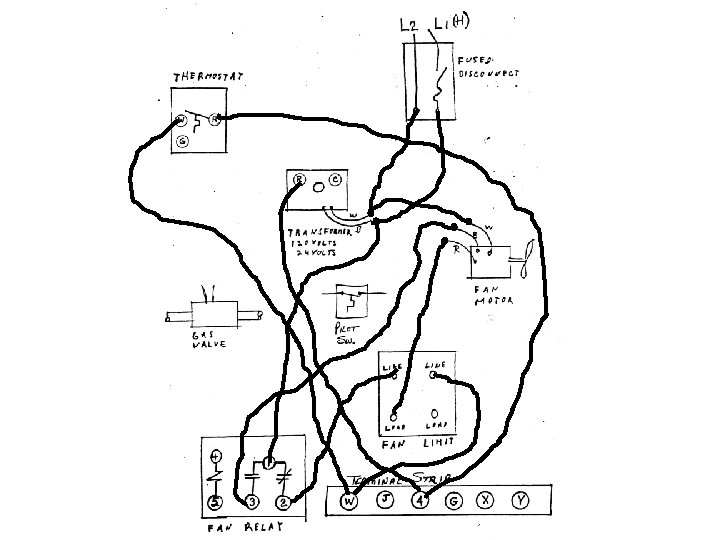
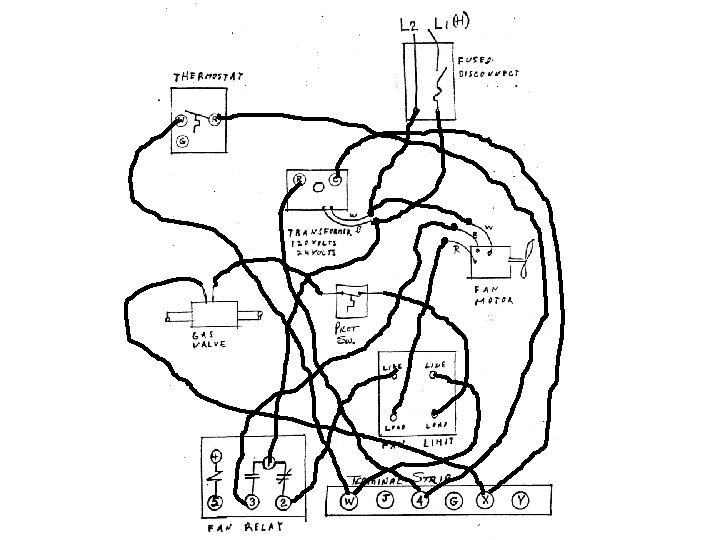
Continue by going out of the fan switch ‘LOAD’ terminal and go to the motors ‘R’ wire. See next 2 slides for help and to check your work.
W R
Continue by going from the motors ‘W’ wire and go to the ‘W’ wire of the transformer. See next 2 slides for help and to check your work.
W R
Continue by going from ‘W’ connection at the transformer back to L 2 at the disconnect. See next 2 slides for help and to check your work.
W R
You have completed the line voltage (120 v) circuit for this schematic. Now move onto the low voltage circuit.
Start at the low voltage side of the transformer (secondary). You will notice that one terminal is marked ‘P’ and the other terminal is marked ‘C. ’ The ‘P’ terminal would be for power and the ‘C’ terminal would be for common.
W R P C
Draw a wire, using your pencil, from the ‘P’ terminal of the secondary of the transformer to terminal ‘ 4’ of the terminal strip. See next 2 slides for help and to check your work.
W R P C
Continue from terminal strip ‘ 4’ terminal and go to terminal ‘R’ of thermostat. See next 2 slides for help and to check your work.
W R P C
Continue from terminal ‘W’ of thermostat to terminal ‘W’ of the terminal strip. See next 2 slides for help and to check your work.
W R P C
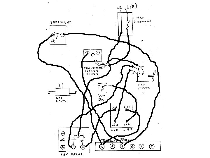
Continue from terminal ‘W’ of the terminal strip to the ‘LINE’ side of the LIMIT. See next 2 slides for help and to check your work.
W R P C
Continue from the ‘LOAD’ side of the LIMIT and arrive at the Pilot Switch. You will notice that I am coming into the right of the switch. Since this is a series connection it would not matter which way I go. And it will help to minimize confusion. See next 2 slides for help and to check your work.
W R P C
Continue from the Pilot Switch onto the gas valve. See next 2 slides for help and to check your work.
W R P C
Continue from the gas valve to terminal ‘X’ of the terminal strip. See next 2 slides for help and to check your work.
W R P C
Finish the low voltage circuit by going from terminal ‘X’ of the terminal strip to the ‘C’ terminal on the transformer. See next 2 slides for help and to check your work.
W R P C
You have now finished taking a schematic and used it to wire the pictorial. The same process would be applied to wire an actual piece of equipment if you had to. This process is also used to trace the wire on a piece of equipment.