Schedule 8 00 11 00 Workshop Arduino Fundamentals


")
")


 • 8 = Backspace / Left - The cursor")
 { Serial. begin(9600); pin. Mode(1, OUTPUT); Serial. write(129); Serial. write(\"Louisiana")


")
 { initialize pin 0 as an output void")
 Try changing the time to 1. 5 seconds")

- Slides: 34
Schedule • 8: 00 -11: 00 Workshop: Arduino Fundamentals • 11: 00 -12: 00 Workshop: Build a follower robot • 1: 30 -3: 00 Symposium: Group 1 – Sanford Bernhardt, Sangster, Kumfer, Michalaka • 3: 10 -5: 00 Workshop: Build a speedometer • 5: 15 -7: 30 Dinner and Symposium: Group 2 – Strevett, Walewski, Villiers, Siegnethaler
Arduino Workshop for Transportation Engineering Educators
DISCLAIMER & USAGE The content of this presentation is for informational purposes only and is intended only for students attending Louisiana Tech University. The author of this information does not make any claims as to the validity or accuracy of the information or methods presented. Any procedures demonstrated here are potentially dangerous and could result in injury or damage. Louisiana Tech University and the State of Louisiana, their officers, employees, agents or volunteers, are not liable or responsible for any injuries, illness, damage or losses which may result from your using the materials or ideas, or from your performing the experiments or procedures depicted in this presentation. If you do not agree, then do not view this content. The copyright label, the Louisiana Tech logo, and the “living with the lab” identifier should not be removed from this presentation. You may modify this work for your own purposes as long as attribution is clearly provided. 3
Building a speedometer Dr. Marisa Orr
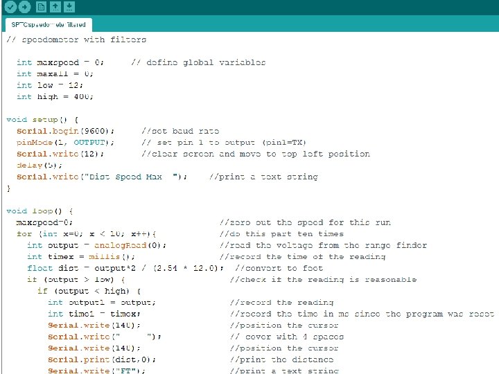
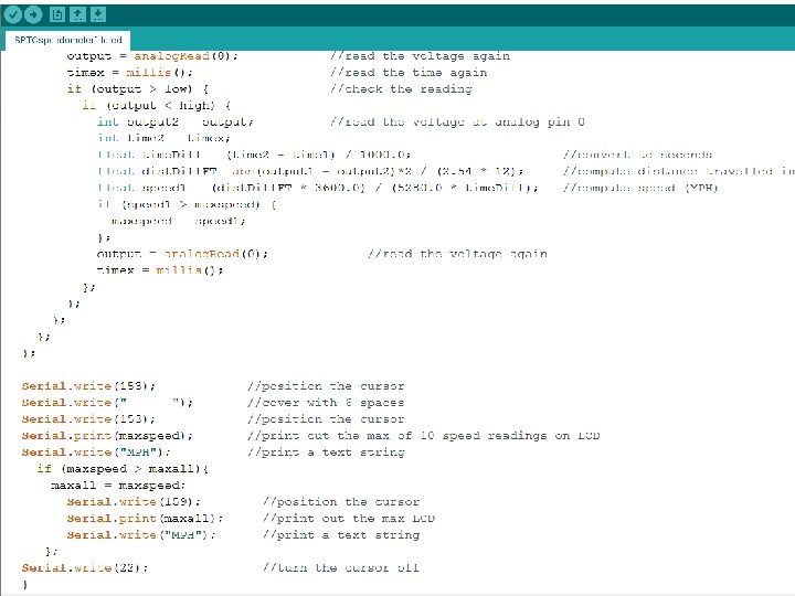
Calculating speed • Need 2 distances and the time between them – New command: • millis() – outputs the time (in milliseconds) since the program was reset – Take a distance measurement, wait a moment, take another
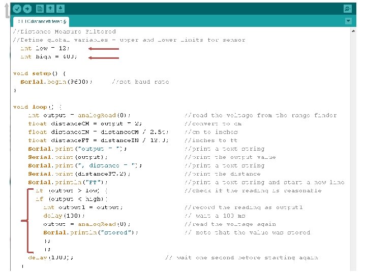
Distance
Sonar • The sensors have a limited range, so we need to filter out bad readings • Using the serial monitor decide what range of values you want to use for calculating speed • pick a high and a low
Speed
Speed (cont. )
ADD AN LCD (LIQUID CRYSTAL DISPLAY)
using a parallax serial LCD with an Arduino Parallax 4 x 20 LCD (part number 27979) with Arduino Duemilanove
LCD wiring RX = wire to receive serial data from Arduino 5 V = power wire GND = ground wire a servo extension is handy for wiring the LCD to the Arduino 13
Arduino wiring TX = wire to transmit serial data from digital I/O pin to LCD ground 5 V power 14
LCD and Arduino together 15
Programming Text: “Louisiana Tech University” is displayed, with character locations chosen to center the text on the first two lines of the LCD Integers: The text “i=“ is printed followed by an integer that varies from 1 to 10 Floating Point Numbers: The text “x=“ is printed followed by a number with four numerals printed to the right of the decimal; the value here ranges from 0. 0010 to 0. 0100 16
row 0, position 3 2 x 16 Cursor Position & Printing to the 4 x 20 LCD Serial. write(131); // move cursor to row 0 position 3 Serial. write("Louisiana Tech"); // print “Louisiana Tech” at (0, 3) 0 1 2 3 4 5 6 7 8 9 10 11 12 13 14 15 16 17 18 19 0 128 129 130 131 132 133 134 135 136 137 138 139 140 141 142 143 144 145 146 147 1 148 149 150 151 152 153 154 155 156 157 158 159 160 161 162 163 164 165 166 167 2 168 169 170 171 172 173 174 175 176 177 178 179 180 181 182 183 184 185 186 187 3 188 189 190 191 192 193 194 195 196 197 198 199 200 201 202 203 204 205 206 207 17
Setting the Communication Rate The dip switches on the back of the LCD are set to SW 1=off and SW 2=on. This causes the LCD to look for data arriving at a rate of 9600 bits per second. The sketch must include. . . Serial. begin(9600); . . . so that the Arduino will know to send data to the LCD at a rate of 9600 bits per second. 18
A Complete Sketch This sketch does not require a special library (only the Serial commands commonly used in sketches) /***************************************/ /* David Hall September 2012 */ /* Example program using a Parallax 4 x 20 LCD to output text and numbers. */ /* The following screen is printed: */ /* ----------*/ /* | Louisiana Tech | */ /* | University | */ /* | i=8 x=0. 0080 | where 1<=i<=10 and 0. 0000<=x<=0. 0100 */ /* ----------*/ /* The program prints out both integers and floating point numbers. The */ /* floating point number is printed to four decimal places. */ /* A partial listing of commands recognized by the LCD is provided below. */ /* See the data sheet for the LCD on the Parallax web site for more details. */ /* Serial. write(8) - move cursor one space left */ /* Serial. write(9) - move cursor one space right */ /* Serial. write(10) - move cursor down one line */ /* Serial. write(12) - clear screen and move cursor to top left */ /* Serial. write(13) - carriage return (will wrap if on last line) */ /* Serial. write(17) - turn backlight on */ /* Serial. write(18) - turn backlight off */ /* Serial. write(21) - turn display off */ /* Serial. write(22) - turn display on, cursor off, no blink */ /* Serial. write(23) - turn display on, cursor off, character blink */ /* Serial. write(24) - turn display on, cursor on, no blink (default) */ /* Serial. write(25) - turn display on, cursor on, character blink */ /* Serial. write(128) moves the cursor to row 0 and position 0 */ /* row and position commands are shown below for all 80 character positions */ /* ROW 0: 128=(0, 0) 129=(0, 1) 130=(0, 2) 131=(0, 3) 132=(0, 4) */ /* 133=(0, 5) 134=(0, 6) 135=(0, 7) 136=(0, 8) 137=(0, 9) */ /* 138=(0, 10) 139=(0, 11) 140=(0, 12) 141=(0, 13) 142=(0, 14) */ /* 143=(0, 15) 144=(0, 16) 145=(0, 17) 146=(0, 18) 147=(0, 19) */ /* ROW 1: 148=(1, 0) 149=(1, 1) 150=(1, 2) 151=(1, 3) 152=(1, 4) */ /* 153=(1, 5) 154=(1, 6) 155=(1, 7) 156=(1, 8) 157=(1, 9) */ /* 158=(1, 10) 159=(1, 11) 160=(1, 12) 161=(1, 13) 162=(1, 14) */ /* 163=(1, 15) 164=(1, 16) 165=(1, 17) 166=(1, 18) 167=(1, 19) */ /* ROW 2: 168=(2, 0) 169=(2, 1) 170=(2, 2) 171=(2, 3) 172=(2, 4) */ /* 173=(2, 5) 174=(2, 6) 175=(2, 7) 176=(2, 8) 177=(2, 9) */ /* 178=(2, 10) 179=(2, 11) 180=(2, 12) 181=(2, 13) 182=(2, 14) */ /* 183=(2, 15) 184=(2, 16) 185=(2, 17) 186=(2, 18) 187=(2, 19) */ /* ROW 3: 188=(3, 0) 189=(3, 1) 190=(3, 2) 191=(3, 3) 192=(3, 4) */ /* 193=(3, 5) 194=(3, 6) 195=(3, 7) 196=(3, 8) 197=(3, 9) */ /* 198=(3, 10) 199=(3, 11) 200=(3, 12) 201=(3, 13) 202=(3, 14) */ /* 203=(3, 15) 204=(3, 16) 205=(3, 17) 206=(3, 18) 207=(3, 19) */ /* To print variables to the LCD, you need to use the Serial. print() */ /* command instead of the Serial. write() command. For example, the command */ /* Serial. print(x, 4) will send variable "x" to the LCD with four digits */ /* beyond the decimal point. */ /***************************************/ See the Parallax website (www. parallax. com) for more details. Custom characters and other features are available for this LCD. When developing your sketch, print things to the LCD screen only once if they do not change. For example, the text in this sketch is printed once in setup(), while the variables are printed repeatedly in loop(). void setup() { Serial. begin(9600); pin. Mode(1, OUTPUT); Serial. write(12); Serial. write(131); Serial. write("Louisiana Tech"); Serial. write(153); Serial. write("University"); Serial. write(190); Serial. write("i= x="); Serial. write(22); } void loop() { float x=0. 0; for (int i=1; i<=10; i++) { x=x+0. 0010; Serial. write(192); Serial. print(i); Serial. write(" "); Serial. write(200); Serial. print(x, 4); delay(1000); } } // // // // // use a baud rate of 9600 bps set pin 1 as an output (pin 1=TX) clear screen & move to top left position move cursor to row 0, position 3 print a text string starting at (0, 3) move cursor to row 1, position 5 print a text string starting at (1, 5) move cursor to row 3, position 2 print text string at (3, 2) turn cursor off to keep screen clean add 0. 001 to variable x move cursor to row 3, position 4 print i at the current cursor position print blanks to cover previous printing move cursor to row 3, position 12 print x to 4 decimal places delay 1 second between printing numbers 19
Other LCD commands Serial. write(#) • 8 = Backspace / Left - The cursor is moved one position to the left. The command doesn’t erase the character. • 9 = Right - The cursor is moved one position to the right. The command doesn’t erase the character. • 10 = Line Feed - The cursor is moved down one line. For the two line LCD model, if on line 0 it goes to line 1. If on line 1, it wraps around to line 0. The horizontal position remains the same. • 12 = Form Feed - The cursor is moved to position 0 on line 0 and the entire display is cleared. Users must pause 5 m. S after this command. • 13 = Carriage Return – For the two line LCD model, if on line 0 the cursor is moved to position 0 on line 1. If on line 1, it wraps around to position 0 on line 0. • 17 = Turn backlight on (only on models 27977, 27979) • 18 = Turn backlight off (Default) • 21 = Turn the display off • 22 = Turn the display on, with cursor off and no blink • 23 = Turn the display on, with cursor off and character blink • 24 = Turn the display on, with cursor on and no blink (Default) • 25 = Turn the display on, with cursor on and character blink
LCD practice void setup() { Serial. begin(9600); pin. Mode(1, OUTPUT); Serial. write(129); Serial. write("Louisiana Tech"); Serial. write(149); Serial. write("i= x="); Serial. write(22); } void loop() { float x=0. 0; for (int i=1; i<=10; i++) { x=x+0. 0010; Serial. write(150); Serial. print(i); Serial. write(" "); Serial. write(167); Serial. print(x, 4); delay(1000); } } // // use a baud rate of 9600 bps set pin 1 as an output (pin 1=TX) clear screen & move to top left position move cursor to row 0, position 1 print a text string starting at ( 0, 1) move cursor to row 1, position 1 print text string at (1, 1) (four spaces after “i=“ turn cursor off to keep screen clean There are 2 mistakes in this code, try it and see if you can find them // // add 0. 001 to variable x move cursor to row 1, position 2 print i at the current cursor position print blanks to cover previous printing move cursor to row 1, position 9 print x to 4 decimal places delay 1 second between printing numbers
living with the lab After downloading your sketch, you may need to press the Arduino reset button to remove “gibberish” that may be printed on the LCD. reset button 22
NOW ADD A LCD DISPLAY TO YOUR SPEEDOMETER CODE
DINNER AND PRESENTATIONS AT THE DAVISON COMPLEX
1. plug in Arduino 2. we will be using digital pin 2 as an output to make an LED go on and off 14 digital I/O pins connect computer to USB plug (I/O = input / output)
the circuit 30
enter and run the following sketch Enter and run the following sketch: void setup() { // initialize the digital pin 2 as an output pin. Mode(2, OUTPUT); } void loop() { digital. Write(2, HIGH); delay(1000); digital. Write(2, LOW); delay(500); } // set the LED on // wait for a second // set the LED off // wait for 500 ms 31
how the sketch works void setup() { initialize pin 0 as an output void loop() { digital. Write(2, HIGH); delay(1000); digital. Write(2, LOW); delay(500); } set pin 0 to HIGH (5 V) wait 1000 ms set pin 0 to LOW (0 V) wait 500 ms 1000 ms voltage (V) infinite loop pin. Mode(2, OUTPUT); } 500 ms 5 V 0 V time (ms) HIGH = 5 V and LOW = 0 V (Always!!!!) 32
now experiment on your own! (1) Try changing the time to 1. 5 seconds on and 1 second off (2) Connect the resistor to digital pin 5 and change the program to match (3) Blink out SOS in Morse code (dot-dot-dash-dash-dot-dot) a. three short pulses (0. 25 seconds each) followed by. . . b. three long pulses (0. 75 second each) followed by. . . c. three short pulses (0. 25 seconds each) followed by. . . d. a brief pause (1 second) e. repeat a through d using an infinite loop 33
Find each command in the reference section of arduino. cc (discuss each command with others at your table) void setup() { // initialize the digital pin as an output: pin. Mode(0, OUTPUT); } void loop() { digital. Write(0, HIGH); // set the LED on delay(1000); // wait for a second digital. Write(0, LOW); // set the LED off delay(500); // wait for 500 ms } The End 34