
SCDTL study for ERHA C Ronsivalle L Picardi
- Slides: 34
SCDTL study for ERHA C. Ronsivalle, L. Picardi ADAM meeting Geneve, 09 -02 -2010
n n TOP-IMPLART (ENEA-ISS-IFO Project in Rome) and EHRA Project (Ruvo di Puglia) do not require radioisotopes production at low energy and foresee for their protontherapy complex a completely linear structure. In the following the design of a SCDTL structure up to 35 Me. V is presented to be used for TOPIMPLART and EHRA Projects; the first part up to 17. 5 Me. V is equal to the structure under development in the framework of the ISPAN Project launched by ENEA-ISS-NRT-CECOM (funded for about 500 K€) ADAM meeting Geneve, 09 -02 -2010
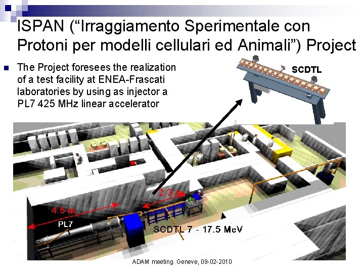
ISPAN (“Irraggiamento Sperimentale con Protoni per modelli cellulari ed Animali”) Project n The Project foresees the realization of a test facility at ENEA-Frascati laboratories by using as injector a PL 7 425 MHz linear accelerator ADAM meeting Geneve, 09 -02 -2010 SCDTL
Outline n n n DESIGN CRITERIA OF SCDTL 35 LAYOUT AND PARAMETERS FROM DESIGN CODE OPTIMIZATION BEAM DYNAMICS IN SCDTL 35: - LINAC code results - Matching with the 7 Me. V injector (PL 7) - Losses distribution (checked also with TSTEP code) - Errors and tolerances study in SCDTL 35 - Start-to-end up to 235 Me. V including LIGHT 35 (from De. Giovanni data. December 2009 version) n CONCLUSIONS ADAM meeting Geneve, 09 -02 -2010
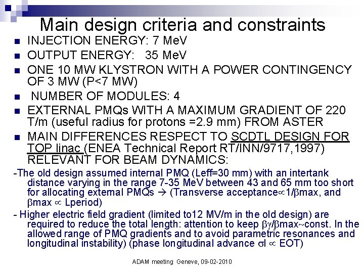
Main design criteria and constraints n n n INJECTION ENERGY: 7 Me. V OUTPUT ENERGY: 35 Me. V ONE 10 MW KLYSTRON WITH A POWER CONTINGENCY OF 3 MW (P<7 MW) NUMBER OF MODULES: 4 EXTERNAL PMQs WITH A MAXIMUM GRADIENT OF 220 T/m (useful radius for protons =2. 9 mm) FROM ASTER MAIN DIFFERENCES RESPECT TO SCDTL DESIGN FOR TOP linac (ENEA Technical Report RT/INN/9717, 1997) RELEVANT FOR BEAM DYNAMICS: -The old design assumed internal PMQ (Leff=30 mm) with an intertank distance varying in the range 7 -35 Me. V between 43 and 65 mm too short for allocating external PMQs (Transverse acceptance 1/ max, and max Lperiod) - Higher electric field gradient (limited to 12 MV/m in the old design) are required to reduce the total length: attention to keep / max const. In the allowed range of PMQ gradients and to avoid parametric resonances and longitudinal instability) (phase longitudinal advance l EOT) ADAM meeting Geneve, 09 -02 -2010
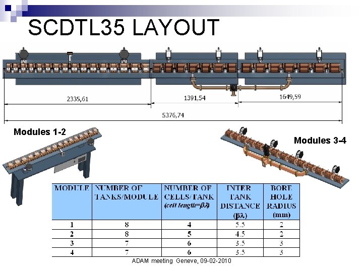
SCDTL 35 LAYOUT Modules 1 -2 Modules 3 -4 ADAM meeting Geneve, 09 -02 -2010
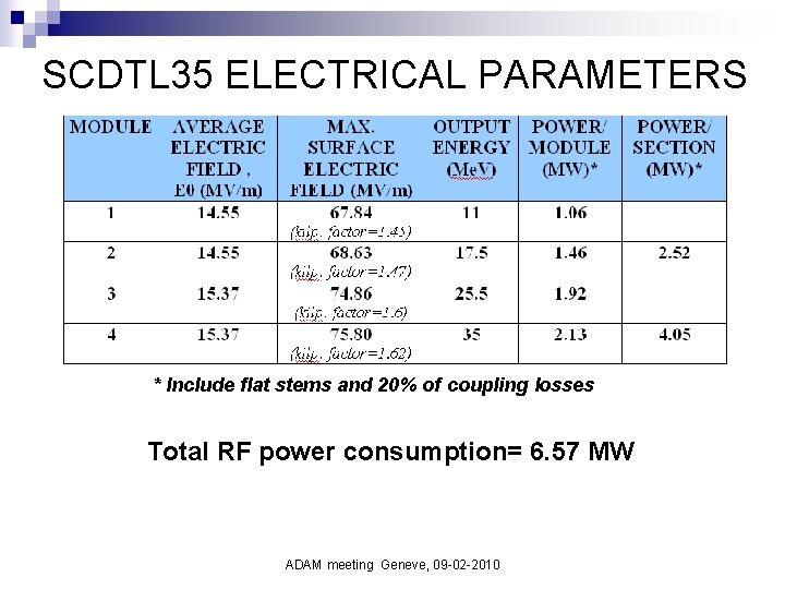
SCDTL 35 ELECTRICAL PARAMETERS * Include flat stems and 20% of coupling losses Total RF power consumption= 6. 57 MW ADAM meeting Geneve, 09 -02 -2010
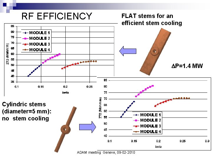
RF EFFICIENCY FLAT stems for an efficient stem cooling P=1. 4 MW Cylindric stems (diameter=5 mm): no stem cooling ADAM meeting Geneve, 09 -02 -2010
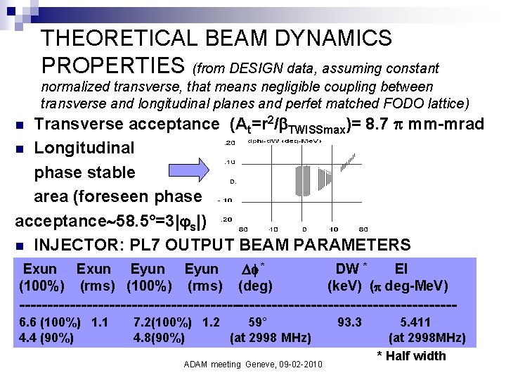
THEORETICAL BEAM DYNAMICS PROPERTIES (from DESIGN data, assuming constant normalized transverse, that means negligible coupling between transverse and longitudinal planes and perfet matched FODO lattice) Transverse acceptance (At=r 2/ TWISSmax)= 8. 7 mm-mrad n Longitudinal phase stable area (foreseen phase acceptance 58. 5°=3| s|) n INJECTOR: PL 7 OUTPUT BEAM PARAMETERS n Exun Eyun (100%) (rms) * (deg) DW * El (ke. V) ( deg-Me. V) ---------------------------------------6. 6 (100%) 1. 1 4. 4 (90%) 7. 2(100%) 1. 2 59° 4. 8(90%) (at 2998 MHz) ADAM meeting Geneve, 09 -02 -2010 93. 3 5. 411 (at 2998 MHz) * Half width
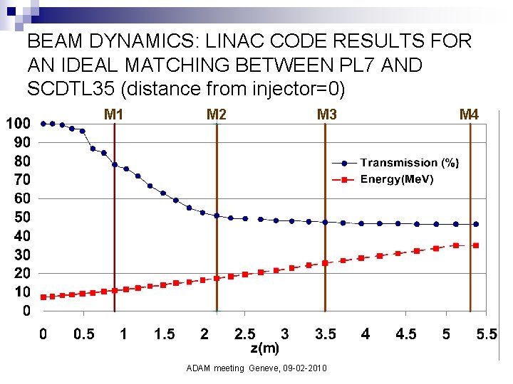
BEAM DYNAMICS: LINAC CODE RESULTS FOR AN IDEAL MATCHING BETWEEN PL 7 AND SCDTL 35 (distance from injector=0) M 1 M 2 M 3 ADAM meeting Geneve, 09 -02 -2010 M 4
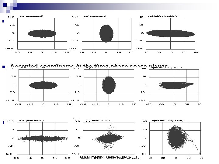
n Input coordinates n Accepted coordinates in the three phase space planes n SCDTL 35 output beam: transmission=46. 3% ADAM meeting Geneve, 09 -02 -2010
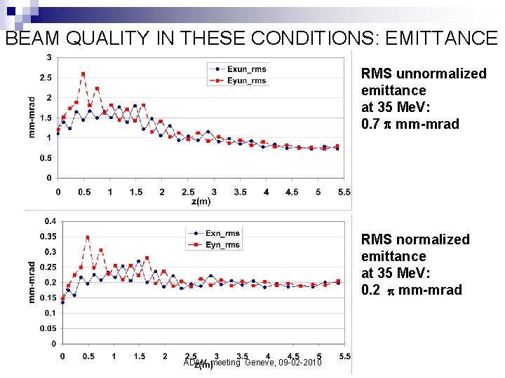
BEAM QUALITY IN THESE CONDITIONS: EMITTANCE RMS unnormalized emittance at 35 Me. V: 0. 7 mm-mrad RMS normalized emittance at 35 Me. V: 0. 2 mm-mrad ADAM meeting Geneve, 09 -02 -2010
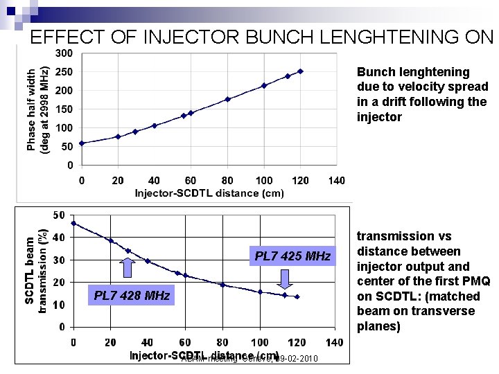
EFFECT OF INJECTOR BUNCH LENGHTENING ON SCDTL TRANSMISSION Bunch lenghtening due to velocity spread in a drift following the injector PL 7 425 MHz PL 7 428 MHz ADAM meeting Geneve, 09 -02 -2010 transmission vs distance between injector output and center of the first PMQ on SCDTL: (matched beam on transverse planes)
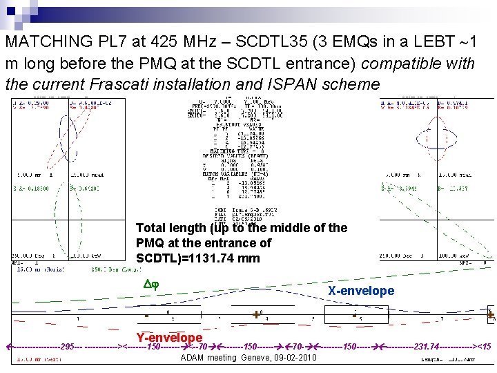
MATCHING PL 7 at 425 MHz – SCDTL 35 (3 EMQs in a LEBT 1 m long before the PMQ at the SCDTL entrance) compatible with the current Frascati installation and ISPAN scheme Total length (up to the middle of the PMQ at the entrance of SCDTL)=1131. 74 mm X-envelope - + Y-envelope - + ---------295 --- ------><-------150 ------- <--70 -------150 ------ - 70 - ----150 -----231. 74 ------><15 ADAM meeting Geneve, 09 -02 -2010
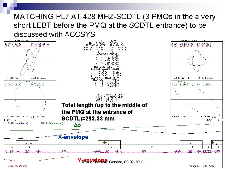
MATCHING PL 7 AT 428 MHZ-SCDTL (3 PMQs in the a very short LEBT before the PMQ at the SCDTL entrance) to be discussed with ACCSYS Total length (up to the middle of the PMQ at the entrance of SCDTL)=293. 33 mm - X-envelope + - + <--16 -><----30 ----- <--------80 -----------30 ---- -<--------80 -----------30 --- <12. 33><15 Y-envelope ADAM meeting Geneve, 09 -02 -2010
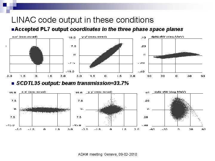
LINAC code output in these conditions n. Accepted n PL 7 output coordinates in the three phase space planes SCDTL 35 output: beam transmission=33. 7% ADAM meeting Geneve, 09 -02 -2010
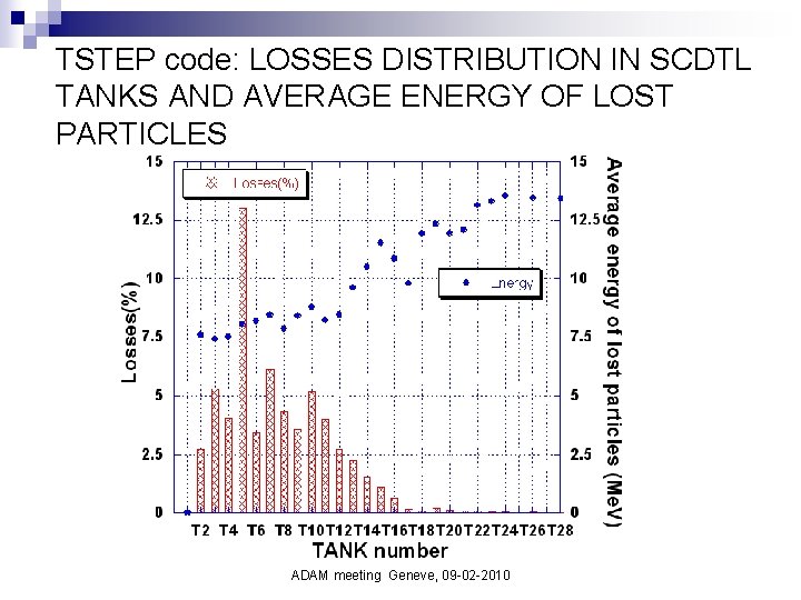
TSTEP code: LOSSES DISTRIBUTION IN SCDTL TANKS AND AVERAGE ENERGY OF LOST PARTICLES ADAM meeting Geneve, 09 -02 -2010
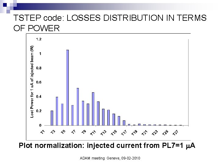
TSTEP code: LOSSES DISTRIBUTION IN TERMS OF POWER Plot normalization: injected current from PL 7=1 A ADAM meeting Geneve, 09 -02 -2010
ERRORS AND TOLERANCES STUDY ADAM meeting Geneve, 09 -02 -2010
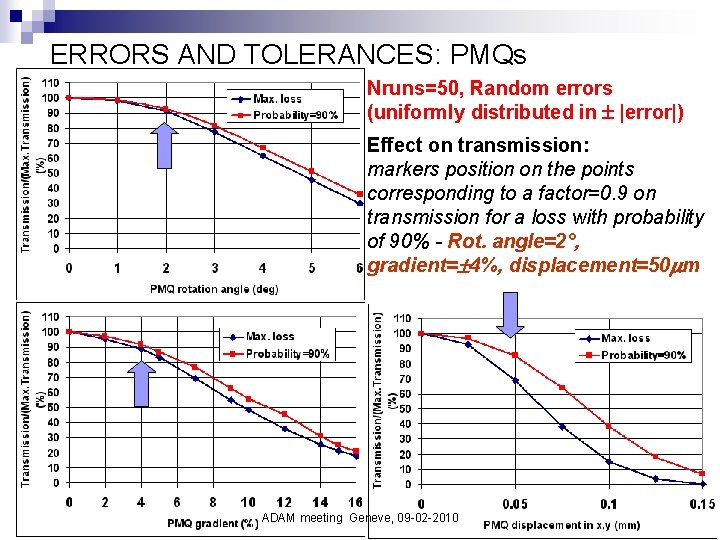
ERRORS AND TOLERANCES: PMQs Nruns=50, Random errors (uniformly distributed in |error|) Effect on transmission: markers position on the points corresponding to a factor=0. 9 on transmission for a loss with probability of 90% - Rot. angle=2°, gradient= 4%, displacement=50 m ADAM meeting Geneve, 09 -02 -2010
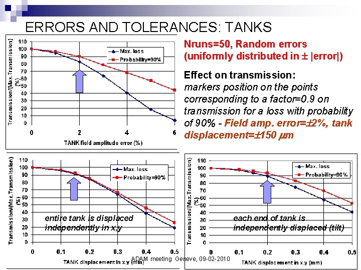
ERRORS AND TOLERANCES: TANKS Nruns=50, Random errors (uniformly distributed in |error|) Effect on transmission: markers position on the points corresponding to a factor=0. 9 on transmission for a loss with probability of 90% - Field amp. error= 2%, tank displacement= 150 m entire tank is displaced independently in x, y ADAM meeting Geneve, 09 -02 -2010 each end of tank is independently displaced (tilt)
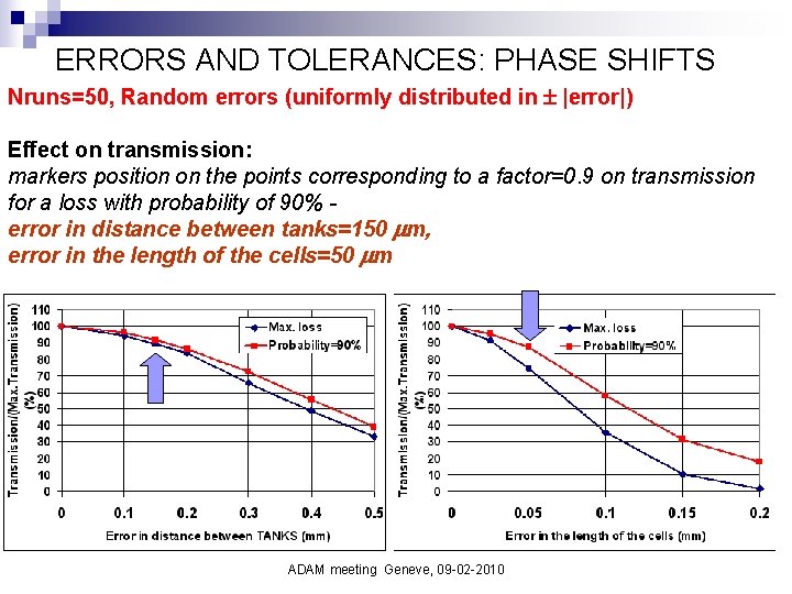
ERRORS AND TOLERANCES: PHASE SHIFTS Nruns=50, Random errors (uniformly distributed in |error|) Effect on transmission: markers position on the points corresponding to a factor=0. 9 on transmission for a loss with probability of 90% error in distance between tanks=150 m, error in the length of the cells=50 m ADAM meeting Geneve, 09 -02 -2010
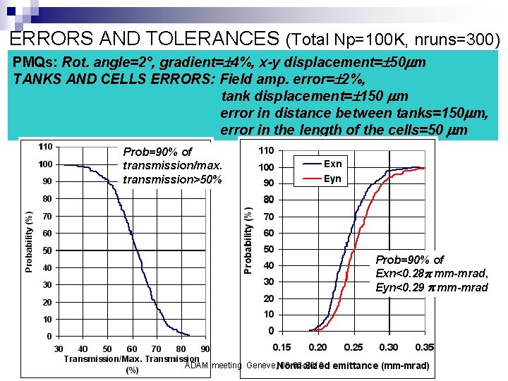
ERRORS AND TOLERANCES (Total Np=100 K, nruns=300) PMQs: Rot. angle=2°, gradient= 4%, x-y displacement= 50 m TANKS AND CELLS ERRORS: Field amp. error= 2%, tank displacement= 150 m error in distance between tanks=150 m, error in the length of the cells=50 m Prob=90% of transmission/max. transmission>50% Prob=90% of Exn<0. 28 mm-mrad, Eyn<0. 29 mm-mrad ADAM meeting Geneve, 09 -02 -2010
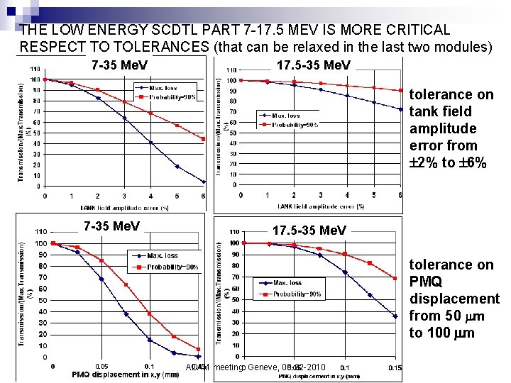
THE LOW ENERGY SCDTL PART 7 -17. 5 MEV IS MORE CRITICAL RESPECT TO TOLERANCES (that can be relaxed in the last two modules) 7 -35 Me. V 17. 5 -35 Me. V tolerance on tank field amplitude error from 2% to 6% 7 -35 Me. V 17. 5 -35 Me. V tolerance on PMQ displacement from 50 m to 100 m ADAM meeting Geneve, 09 -02 -2010
START-TO-END (7 -235 Me. V) ADAM meeting Geneve, 09 -02 -2010
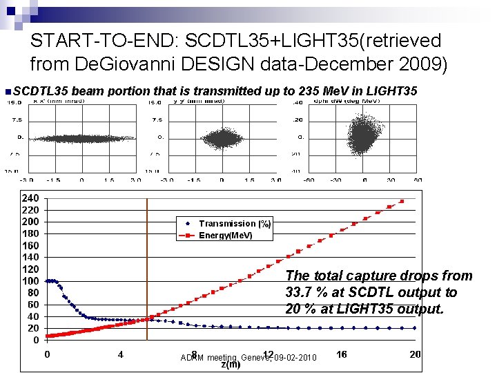
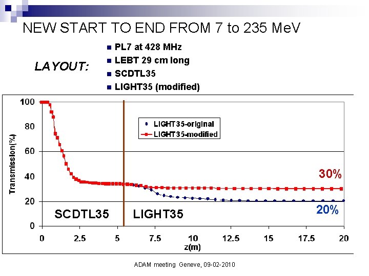
START-TO-END: SCDTL 35+LIGHT 35(retrieved from De. Giovanni DESIGN data-December 2009) n. SCDTL 35 beam portion that is transmitted up to 235 Me. V in LIGHT 35 The total capture drops from 33. 7 % at SCDTL output to 20 % at LIGHT 35 output. ADAM meeting Geneve, 09 -02 -2010
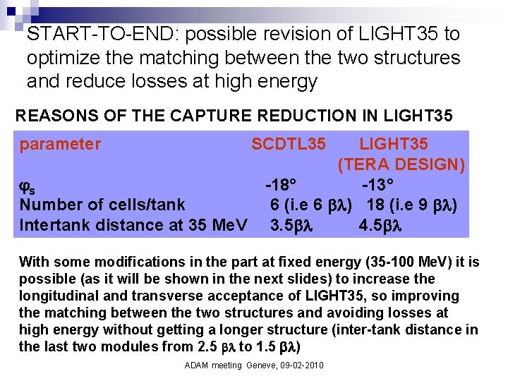
START-TO-END: possible revision of LIGHT 35 to optimize the matching between the two structures and reduce losses at high energy REASONS OF THE CAPTURE REDUCTION IN LIGHT 35 parameter SCDTL 35 s Number of cells/tank Intertank distance at 35 Me. V LIGHT 35 (TERA DESIGN) -18° -13° 6 (i. e 6 ) 18 (i. e 9 ) 3. 5 4. 5 With some modifications in the part at fixed energy (35 -100 Me. V) it is possible (as it will be shown in the next slides) to increase the longitudinal and transverse acceptance of LIGHT 35, so improving the matching between the two structures and avoiding losses at high energy without getting a longer structure (inter-tank distance in the last two modules from 2. 5 to 1. 5 ) ADAM meeting Geneve, 09 -02 -2010
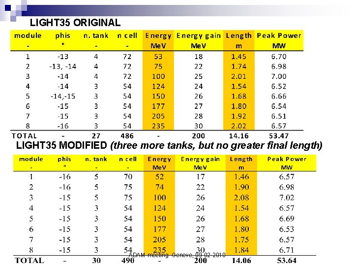
LIGHT 35 ORIGINAL LIGHT 35 MODIFIED (three more tanks, but no greater final length) ADAM meeting Geneve, 09 -02 -2010
NEW START TO END FROM 7 to 235 Me. V PL 7 at 428 MHz n LEBT 29 cm long n SCDTL 35 n LIGHT 35 (modified) n LAYOUT: 30% SCDTL 35 LIGHT 35 ADAM meeting Geneve, 09 -02 -2010 20%
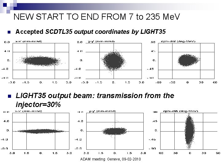
NEW START TO END FROM 7 to 235 Me. V n Accepted SCDTL 35 output coordinates by LIGHT 35 n LIGHT 35 output beam: transmission from the injector=30% ADAM meeting Geneve, 09 -02 -2010
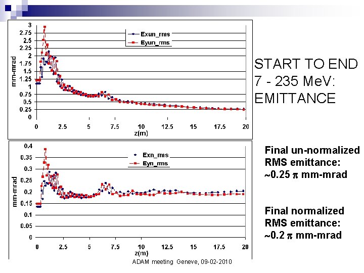
START TO END 7 - 235 Me. V: EMITTANCE Final un-normalized RMS emittance: 0. 25 mm-mrad Final normalized RMS emittance: 0. 2 mm-mrad ADAM meeting Geneve, 09 -02 -2010
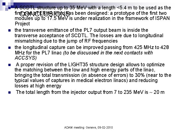
n n n A SCDTL structure up to 35 Me. V with a length <5. 4 m to be used as the first part of ERHA linac has been designed: a prototype of the first two CONCLUSIONS modules up to 17. 5 Me. V is under realization in the framework of ISPAN Project the transverse emittance of the PL 7 output beam is inside the transverse acceptance of SCDTL. The losses are due to longitudinal mismatching due to the jump of RF frequencies the longitudinal capture can be improved passing from 425 MHz to 428 MHz for the PL 7 linac (to be discussed in the next contacts with ACCSYS) A proper revision of the LIGHT 35 structure design allows to optimize the matching between the low and high energy parts of the linac, bringing the total transmission (in absence of errors) to 30% (near to the typical values of captures in medical electron linacs) and reducing losses at high energy The total length from the injector output from 7 to 235 Me. V is 20 m ADAM meeting Geneve, 09 -02 -2010
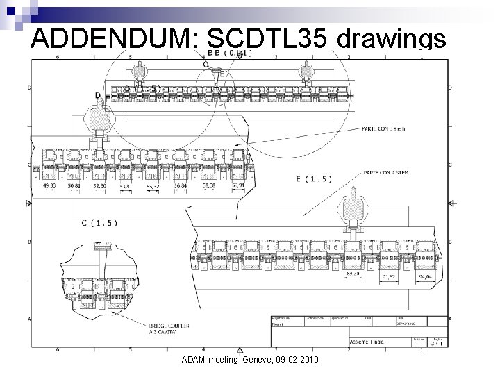
ADDENDUM: SCDTL 35 drawings ADAM meeting Geneve, 09 -02 -2010
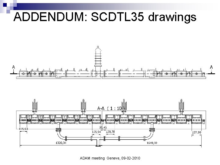
ADDENDUM: SCDTL 35 drawings ADAM meeting Geneve, 09 -02 -2010