Scattering by aggregates and layers of closely packed

Scattering by aggregates and layers of closely packed particles Sanaz Vahidinia Jeffrey Cuzzi, Bruce Draine, Frank Bridges

Overview • Introduction – Light scattering in nature • Saturn’s F ring aggregates – Scattering from diffuse particle layer – Independent scattering – Cassini VIMS data, modeling, and results • Regolith scattering – Scattering from compact particle layers – Interference effects – motivation, current models, our new model – results • Future work

1. diffuse layer 2. diffuse aggregate layer 3. compact layer

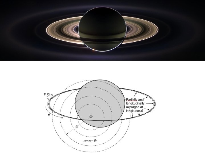
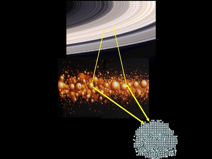
Part 1: Studies of Saturn’s F ring particles As aggregates
 (vis, near-IR mapping spectrometer) ISS (WA,")
Cassini’s Telescopes RSS, Radar MIMI (neutrons ! ) (vis, near-IR mapping spectrometer) ISS (WA, NA cameras) RPWS (AM, FM) UVIS Ultraviolet imaging spectrograph (occultations, mapping) CIRS Composite infrared Spectrometer (thermal emission)

D C B CD A F ISS approach color composite
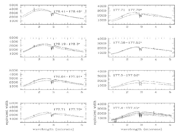
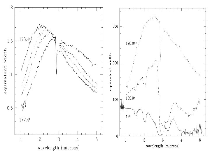

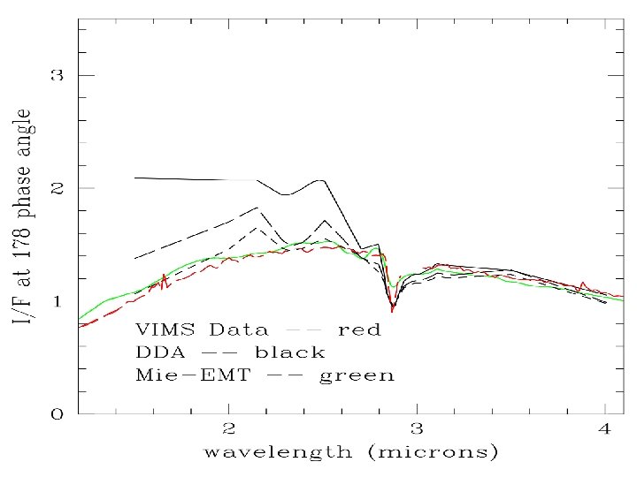
what kind of particles could the F ring particles be? solid, porous, or aggregates or ? ? ? solid homogeneous particle Mie theory porous homogeneous particle Mie theory + EMT aggregate DDA

solid carbon particles vs. solid ice particles vs. data
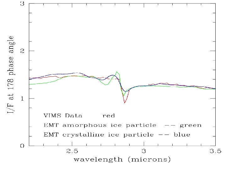


what kind of particles could the F ring particles be? solid, porous, or aggregates or ? ? ? solid homogeneous particle Mie theory porous homogeneous particle Mie theory + EMT aggregate DDA

Discrete Dipole Approximation • Model each dielectric grain with an array of N polarizable dipoles with polarizability . • Assign polarizability such that the dipole lattice exhibits the macroscopic dielectric constant of the material. • Each dipole is driven by an incident field and the field of all other oscillators in the lattice. • The steady state polarization or field in the material is found by an iterative method. Pj = Ej = ·(Ei + k 2 (Pj * G) ) - 1 = 4 N / (1 - 4 N /3) 2 m(d / ) < 1/2 DDA Constraint
 = Qa + Qs = ext / r 2 albedo (w)")
extinction efficiency (Qext) = Qa + Qs = ext / r 2 albedo (w) = Qs / Qext phase (p) = phase function I / F = Qext * w * p * n * r 2

The “toy model”

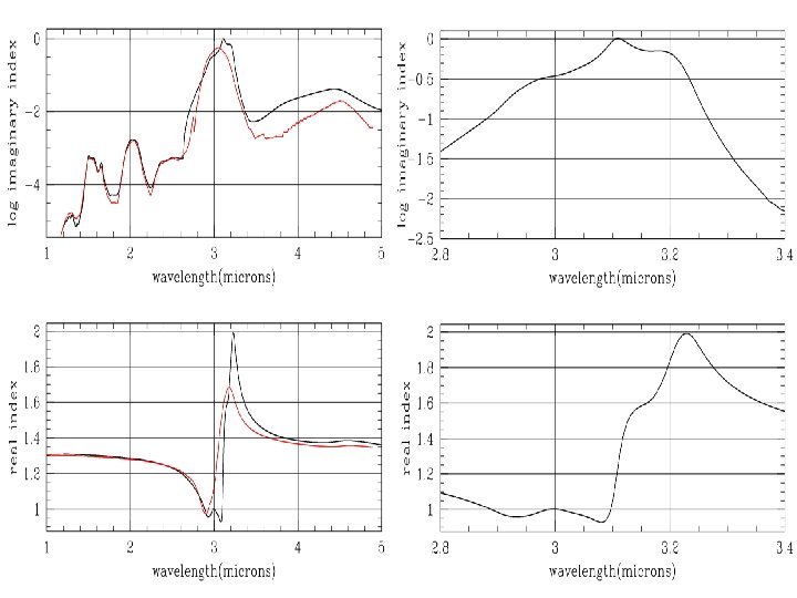
Part 1 conclusions: • F ring particles are not well modeled by uniform density spheres, even if arbitrary density is allowed • Aggregates fit better and allow fit to overall shape of spectral Forward scattering I/F AND depth of single observed absorption feature • Aggregates are more effective scatterers per unit mass; toy model explains why (interfaces) • Single abs feature has been explained as Christiansen frequency and allows us to discriminate between crystalline and amorphous ice • F ring aggregate particles have a moderately narrow size distribution

Part 2: Regolith radiative transfer: A new approach with applications To many granular surfaces

1. diffuse layer 2. diffuse aggregate layer 3. compact layer

Saturn’s entire B ring HST IRTF model 98% water ice, 2% carbon, 1% tholins R F. Poulet et al. (2003) wavelength (microns) Groundbased reflectance spectrum: water ice bands and reddish material Certain regions get more “polluted” wavelength, microns

Grains are good absorbers of short Grains start to scatter radiation in this region 1. 0 B A C Ring particles become good scatterers in the microwave region 0. 5 10 1000 Wavelength ( m) Spilker et al. (2005) Ring emissivities of the A, B, and C rings as a function of wavelength. • Roll off is the transition region between good absorbers and perfect reflectors. • This region is difficult to model due to closely packed grains and grain sizes comparable to .

Thermal IR and microwave: change from emitting to scattering behavior Most ring particles are wavelength size (cm-m) and Composed almost entirely (>90%) of water ice; Transition region (100 - few mm) poorly characterized Data tabulated in Esposito et al 984

Review of current RRT models and sample calculation of Quartz emissivity using current model…motivation for development of our model

Equation of Transfer Ir I 0 0 0 0 It P = particle phase function, which gives the angular distribution and polarization of scattered light for any polarization of incident radiation. g = cos P 11 d /4 , anisotropy parameter characterizing the shape of the phase function. w = single scattering albedo. Defined as the fraction scattered, of the total energy removed from the incident beam. Methods of solving the Transfer Equation for plane parallel layers

Current RRT models Some of the current transfer solutions can be summarized in two parts Calculate grain Albedo (w) using: Mie theory … Spherical particles, well separated (Conel, Hansen, . . ) Ray optics … Particles large compared to wavelength, allows for irregular particles (Hapke) Multiple scattering calculation for layer: Isotropic scattering in a homogenous semi infinite layer can be solved by Chandrasekhar's semi-analytic H-function. The H function is a nonlinear integral equation used to numerically solve the reflection from an infinite layer. Anisotropic scattering can be solved using van de Hulst’s Similarity relations. This method approximates complex phase functions in terms of solutions for simpler phase functions (specifically isotropic phase functions). (Cuzzi & Estrada, Shkuratov, Conel…) The Doubling/Adding method is a numerical approach where the overall transfer properties of one layer is calculated by equating the emergent radiation from an arbitrary layer to the incident radiation upon the layer in question. (Hansen, Eddington…)

Emissivity of a layer of particles Bc=Black body radiation intensity Bc Black body surface at Tc Bc • • Black body radiation gets absorbed, scattered, and re-emitted by the layer. The radiation contributions from the layer can be broken up into the following: 1) Direct transmission of black body radiation through the layer. 3) Diffusely scattered radiation reflected by the layer. 2) Diffusely scattered radiation transmitted through the layer. 4) Emitted radiation from the layer. Conservation of Energy ~
 d")
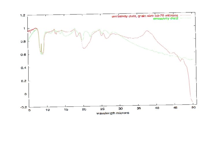
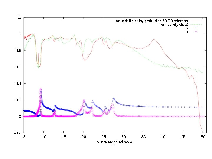
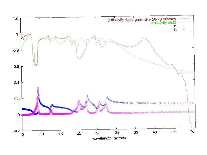
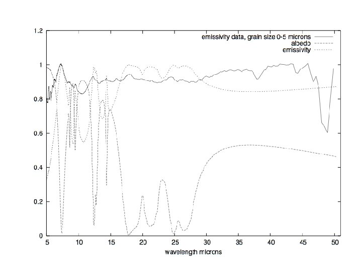
Outline of Mie/similarity calculation for quartz emissivity data A = S( , ) d d o = ring particle spherical albedo using van de Hulst’s similarity parameter S = [(1 - w) / (1 - w • g)]1/2 A = (1 - S )(1 -0. 139 S ) / (1+1. 175 S ) Emissivity = 1 - A
 and g • Similarity transformation for particle")
• Mie scattering for grain albedo(w) and g • Similarity transformation for particle (or integrated) albedo Integrated emissivity = 1 - Integrated Albedo Data courtesy J. Michalski

Current models don’t match the emissivity data. Current models make various simplifying assumptions and do not account for close packing, interference effects, and irregular particles. We need to develop an RRT model that takes all these effects into account

Discrete Dipole Approximation • Model dielectric grain with an array of N polarizable dipoles with polarizability . • Assign polarizability such that the dipole lattice exhibits the macroscopic dielectric constant of the material. • Each dipole is driven by an incident field and the field of all other oscillators in the lattice. • The steady state polarization or field in the material is found by an iterative method. Pj = Ej = ·(Ei + k 2 (Pj * G) ) - 1 = 4 N / (1 - 4 N /3) 2 m(d / ) < 1/2 DDA Constraint

Discrete Dipole Approximation applied to grainy surface
")
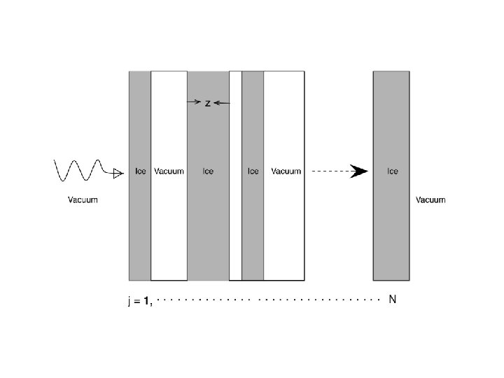
Layer radiative transfer s T {s + T} ( )

Scattered field in the shadow zone
 Note")
Scattered field on a plane in the near field (either reflection or transmission) Note periodic boundary conditions x y E(x, y) = k 2 (Pj * G) FFT E( , )
 2 -D vector field Fourier")
Angular Spectrum G = Green’s function (J. D. Jackson) 2 -D vector field Fourier transform vector field to k-space power spectrum

x Angular distribution of scattered intensity evanescent waves occur when: z y Resolution Specifications

• Dielectric slab test Simulate a homogeneous dielectric layer with DDA-PBC code. Calculate reflection and transmission from the layer with the near field method. Compare R and T with Fresnel coefficients. • Granular runs Run a granular layer with various porosities. Examine transmission and reflection as a function of particle packing.

Io R T

Specular beam in k-space Specular reflection: reflected beam is localized in frequency space at three emission angles corresponding to three incident zenith angles 20 o, 40 o, and 60 o.

Granular layers for various porosities

Optical depth studies of granular layers z • Calculate Q from the optical depth and compare with current mie models • Use optical depth for the adding code

Next step in future work………

Adding/Doubling of Grain layer Scattering Reflectivity s T By using the adding/doubling technique we can propagate the transmitted radiation throughout the layers and obtain the final reflectivity of the regolith.

Part 2 Conclusion: I have developed an end-to-end approach for regolith radiative transfer for monomers Of arbitrary size, shape, and packing density Approach has been tested in several regimes Intriguing results are already apparent in three different layer porosities (extinction does not scale simply as “tau” of independent particles, spacing does matter. . ) Next steps for future work: Detailed spectral modeling of quartz data showing the effect of porosity, monomer shape, asperities, edges, etc on spectral bands Adding doubling method for building thicker layers

The End.

Regolith = A layer of loose, heterogeneous material covering a surface. Regolith ? Saturn’s ring particles
 = k 2 (Pj")
Scattered field in the shadow zone y x E(x, y) = k 2 (Pj * G) FFT E( , )

Densely packed ring due to inelastic collisions? 30 m thick Optically thick, Physically thin Salo et al, French et al Gentle inelastic collisions and weak gravity between particles give the rings the quality of a viscous fluid Goldreich & Tremaine 1978, Bridges et al 1984 et seq. , Wisdom & Tremaine 1988, Salo 1992

Cassini RSS 3 wavelength occultation Blue: small particles; red; larger particles, white: high tau Marouf et al

CIRS measurement of ring Particle temperatures 70 K 115 K

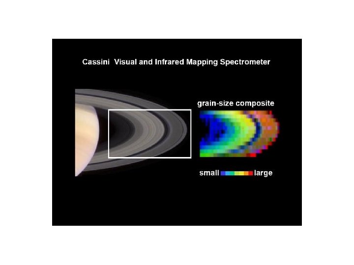
Regional composition variations Cassini VIMS results Detailed, spatially resolved spectra show spatially variable near-IR slope interpreted as “Fe 2+” (silicate) content More in regions where particles are darker Courtesy P. Nicholson & M. Hedman

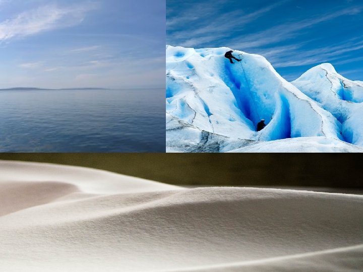
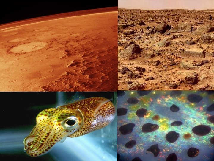
Overview Intro to scattering, why is scattering of light important in nature: fun pictures. . blue sky, snow bank, saturns rings, …etc continuum medium scattering what is a regolith? (regolith = A layer of loose, heterogeneous material covering a surface. ) made up of grains, grains can form aggregates. . interesting optical regimes: volume scattering, surface scattering, Christiansen frequency, restrahlen bands, …etc Lead to Fring intro: Cassini spacecraft Ring system overview Ring particle size and composition high phase geometry and data ice indices modeling mie emt dda toy model conclusions Just a few bullets here, of course. . Layer Radiative Transfer review Some unanswered questions: Quartz powder emissivity data and modeling Cassini-CIRS (far infrared) data Regolith Radiative Transfer (RRT) Model 1. Discrete Dipole Approximation Introduction

Adding/Doubling Calculations using the matrix operator theory Calculate transmission and reflection for a combined layer from the known transmission and reflection operators from two separate layers. 0 2

Emissivity calculation and comparison with CIRS ~ CIRS measures intensity I I = B (Tp) (1 - e- / )

Conclusion • Current RRT models do not account for close packing, coherent scattering, and irregular particles. • CIRS data can probe deeper into the particle and with our model we can get an idea on how impurities are buried within the regolith. • This model has many applications in remote sensing of granular surfaces of solar system objects (icy satellites, comets, planetary surfaces, . . ). Current and future work • Obtain S, T functions for regolith layer with DDA using the near field calculation. • Given the S & T functions from DDA, use the adding/doubling code to build an optically thick regolith. • Calculate emissivity and vary refractive indices to find best fit with CIRS data. • Use the refractive indices to infer composition. • Use laboratory data to test new model against prior models (Hapke, Mie, etc. . ).
- Slides: 70