
SC Smart Grid Products Alberta Power Industry Consortium
S&C Smart Grid Products Alberta Power Industry Consortium Smart Grid Forum © 2009 Steve Lange – S&C Electric November 5, 2009 www. sandc. com
Smart Grid Distribution Requirements • Flexible and Scalable • Secure • Self-healing • Adaptive (capacity, power flow, load, protection) • Capable of Supporting DER • Integrate with AMI, DMS, OMS, GIS, etc • Built around Modern Communications Systems • Plug-and-Play and Self-diagnostic • Upgradeable and Remotely Administered © 2009 www. sandc. com
Why is Distributed Control Better for DA? • Speed • Increased Security • Lower Lifecycle Cost • Flexibility and Scalability • Reliability • Lower Communications Bandwidth Demand © 2009 www. sandc. com
Enabling the Smart Grid Today – S&C Products • Intelli. TEAM II Automatic Restoration System • Universal Interface Module • Intelli. Rupter Pulse. Closer • Speed. Net Radio • Next Generation Intelli. TEAM Other products • Intelli. CAP Capacitor Controls • Na. S Battery Energy Storage • CES (Community Energy Storage) © 2009 www. sandc. com
Intelli. TEAM Concept • Original Intelli. TEAM – Introduced in 1996 – – – – Limited to 2 sources of power Must contain an open switch No radial circuits Real-time load data to prevent overloads Automatic return to normal configuration DNP 3. 0 protocol Distributed intelligence © 2009 www. sandc. com
Intelli. TEAM II – Evolution Self-healing Fault Isolation and Circuit Restoration System • Introduced in 2002 • Proven technology used by over 130 utilities • Easily applied to complex feeder systems • Accommodate more than two sources of power • Accommodate multiple tie points to adjacent feeders • Real-time load data to prevent overloads • Distributed Intelligence © 2009 www. sandc. com
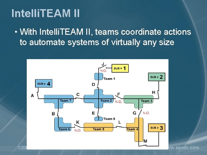
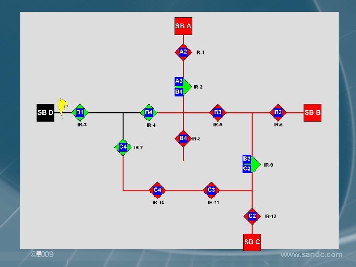
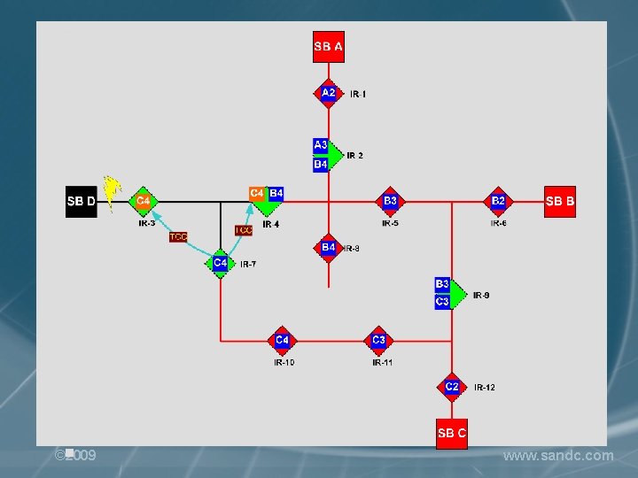
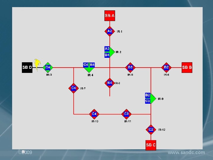
Intelli. TEAM II • With Intelli. TEAM II, teams coordinate actions to automate systems of virtually any size © 2009 www. sandc. com
Intelli. TEAM II – What is It? • Rule-based software system • Does not require custom programming • Does not require extensive validation and testing • No reprogramming when new devices are added to the grid or when the topology of the electrical system is rearranged – just reconfigure controls • Virtually maintenance-free and self-diagnostic • Communicates using standard protocols (DNP) over any communications medium © 2009 www. sandc. com
Intelli. TEAM II – Key Features • Intelli. TEAM restores power in seconds without overloading any section of the power grid • Can handle multiple fault contingencies • Restores power from alternate sources as long as there is capacity left, whether the power source is conventional, DER, wind, storage, etc. • Intelli. TEAM supports islanding with Na. S storage systems. © 2009 www. sandc. com
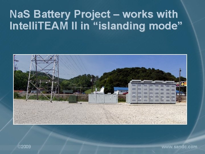
Na. S Battery Project – works with Intelli. TEAM II in “islanding mode” © 2009 www. sandc. com
Intelli. TEAM II – Instant Replay 2 E Rev Flt F 15+Flt F 18. Sw. Log © 2009 www. sandc. com
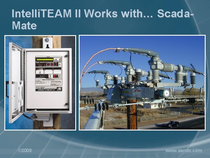
Intelli. TEAM II Works with… Scada. Mate © 2009 www. sandc. com
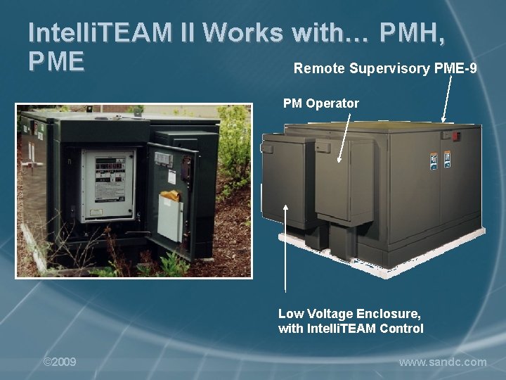
Intelli. TEAM II Works with… PMH, PME Remote Supervisory PME-9 PM Operator Low Voltage Enclosure, with Intelli. TEAM Control © 2009 www. sandc. com
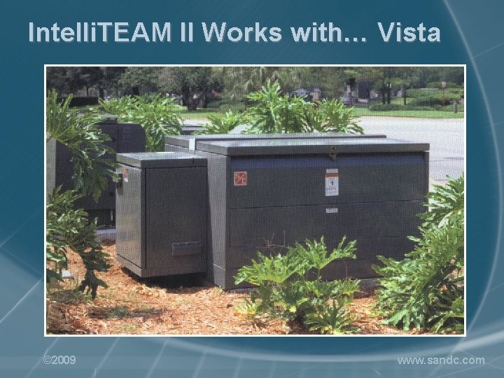
Intelli. TEAM II Works with… Vista © 2009 www. sandc. com
Intelli. TEAM II Works with… non-S&C Devices via the Universal Interface Module (UIM) • Intelli. TEAM is an Open System • Allows a relay, recloser control, or switch control to be a part of an Intelli. TEAM system • UIM polls the External Device to acquire the data it needs to make Intelli. TEAM II logic decisions • Protective functions of the relay or recloser are not affected • Intelli. TEAM II takes over after the device locks out © 2009 www. sandc. com
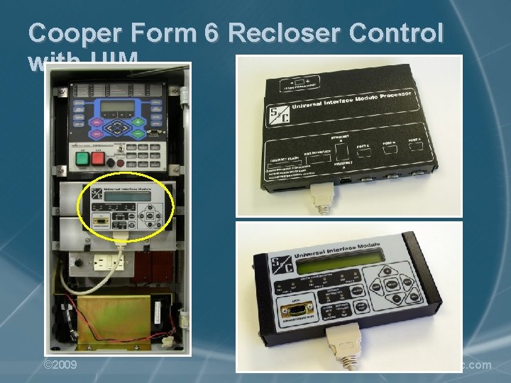
Cooper Form 6 Recloser Control with UIM © 2009 www. sandc. com
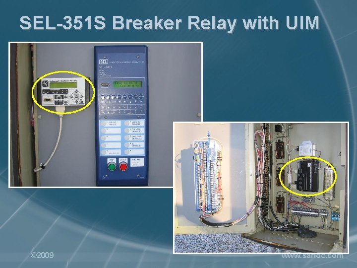
SEL-351 S Breaker Relay with UIM © 2009 www. sandc. com
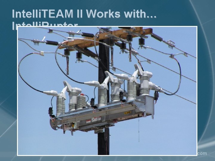
Intelli. TEAM II Works with… Intelli. Rupter © 2009 www. sandc. com
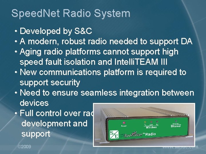
Speed. Net Radio System • Developed by S&C • A modern, robust radio needed to support DA • Aging radio platforms cannot support high speed fault isolation and Intelli. TEAM III • New communications platform is required to support security • Need to ensure seamless integration between devices • Full control over radio development and support © 2009 www. sandc. com
Speed. Net – key features • Operates in the unlicensed 902 to 928 MHz band • Wireless router for fixed mesh networks • High data rates – 650 kbaud • Very low message latency – 5 ms per hop • Support mesh and point-to-multi point networks • Fully scalable • Very reliable • Fully secure with 128 -bit AES encryption • Multi-level administrative password access © 2009 www. sandc. com
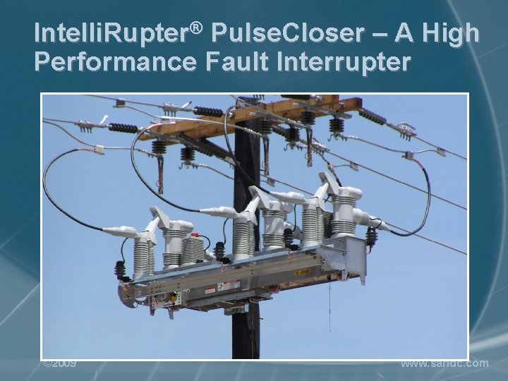
Intelli. Rupter® Pulse. Closer – A High Performance Fault Interrupter © 2009 www. sandc. com
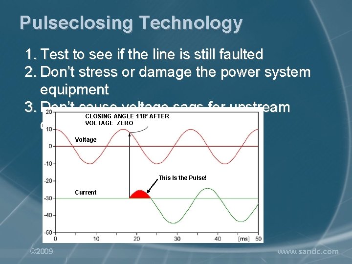
Pulseclosing Technology 1. Test to see if the line is still faulted 2. Don’t stress or damage the power system equipment 3. Don’t cause voltage sags for upstream customers CLOSING ANGLE 118° AFTER VOLTAGE ZERO Voltage This Is the Pulse! Current © 2009 www. sandc. com
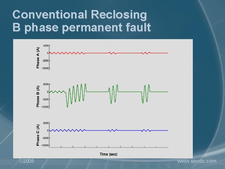
Conventional Reclosing B phase permanent fault © 2009 www. sandc. com
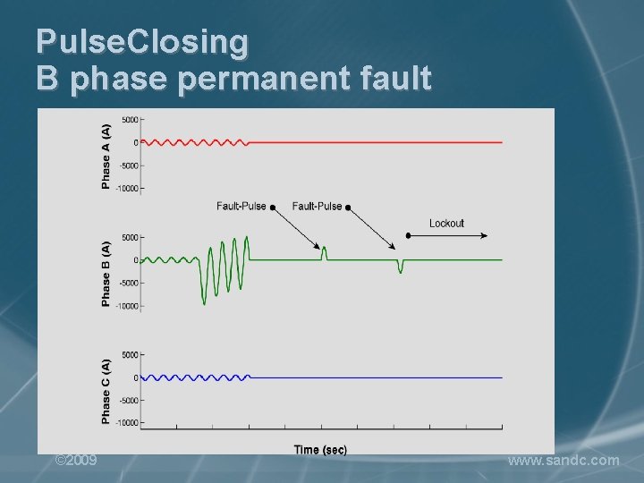
Pulse. Closing B phase permanent fault © 2009 www. sandc. com
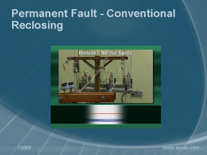
Permanent Fault - Conventional Reclosing © 2009 www. sandc. com
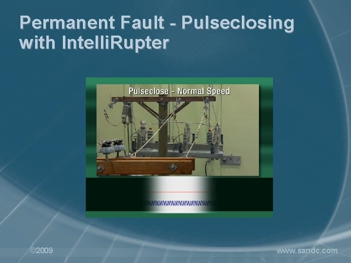
Permanent Fault - Pulseclosing with Intelli. Rupter © 2009 www. sandc. com
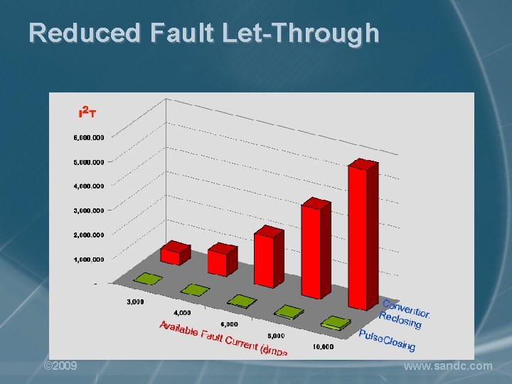
Reduced Fault Let-Through © 2009 www. sandc. com

EPRI Pulse. Closer Testing at Hydro-Quebec / IREQ Pulse. Finding Test Explanation © 2009 www. sandc. com
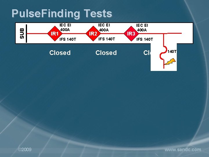
SUB Pulse. Finding Tests IR 1 IEC EI 400 A IFS 140 T Closed © 2009 IR 2 IEC EI 400 A IFS 140 T Closed IR 3 IEC EI 400 A IFS 140 T Closed 140 T www. sandc. com
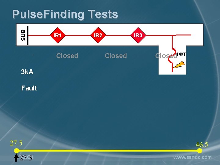
SUB Pulse. Finding Tests IR 1 - Closed IR 2 IR 3 Closed 140 T 3 k. A Fault 27. 5 © 2009 27. 5 46. 5 www. sandc. com
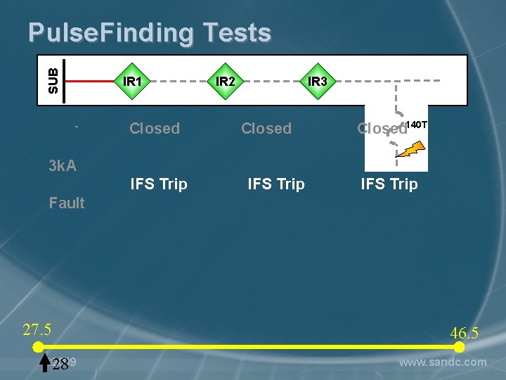
SUB Pulse. Finding Tests IR 1 - Closed IR 2 IR 3 Closed 140 T 3 k. A IFS Trip Fault 27. 5 © 2009 28 46. 5 www. sandc. com
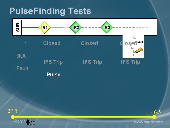
SUB Pulse. Finding Tests IR 1 Closed - IR 2 IR 3 Closed 140 T 3 k. A IFS Trip Fault Pulse 27. 5 © 2009 46. 5 30 www. sandc. com
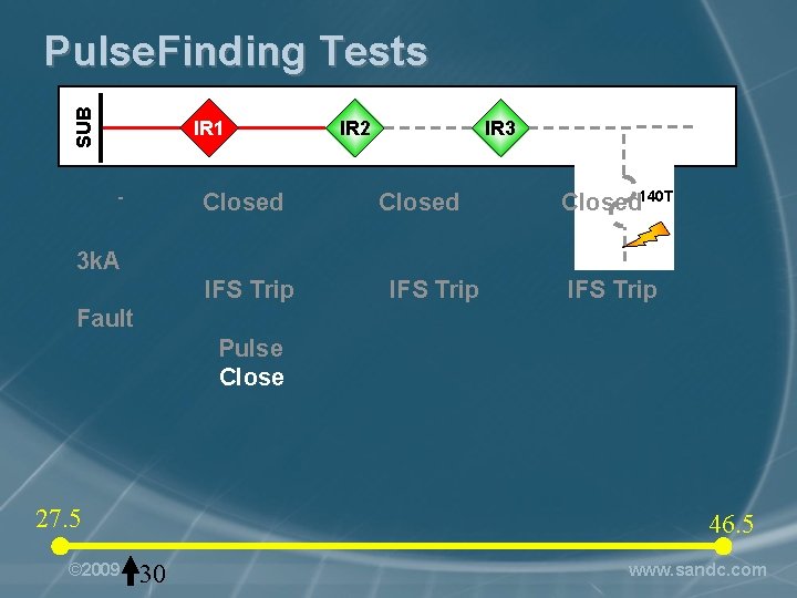
SUB Pulse. Finding Tests IR 1 Closed - IR 2 IR 3 Closed 140 T 3 k. A IFS Trip Fault Pulse Close 27. 5 © 2009 46. 5 30 www. sandc. com
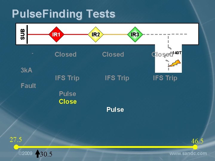
SUB Pulse. Finding Tests IR 1 Closed - IR 2 IR 3 Closed 140 T 3 k. A IFS Trip Fault Pulse Close Pulse 27. 5 © 2009 46. 5 30. 5 www. sandc. com
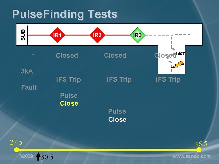
SUB Pulse. Finding Tests IR 1 Closed - IR 2 IR 3 Closed 140 T 3 k. A IFS Trip Fault Pulse Close 27. 5 © 2009 46. 5 30. 5 www. sandc. com
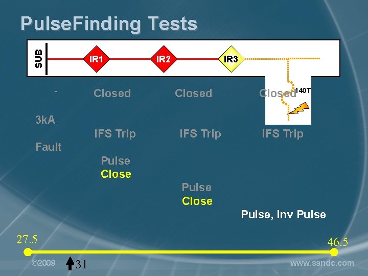
SUB Pulse. Finding Tests IR 1 Closed - IR 2 IR 3 Closed 140 T 3 k. A IFS Trip Fault Pulse Close Pulse, Inv Pulse 27. 5 © 2009 46. 5 31 www. sandc. com
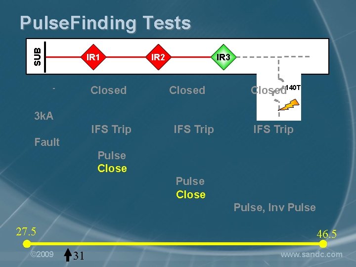
SUB Pulse. Finding Tests IR 1 Closed - IR 2 IR 3 Closed 140 T 3 k. A IFS Trip Fault Pulse Close Pulse, Inv Pulse 27. 5 © 2009 46. 5 31 www. sandc. com
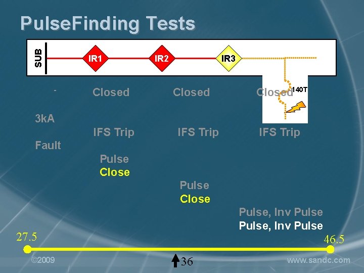
SUB Pulse. Finding Tests IR 1 - Closed IR 2 IR 3 Closed 140 T 3 k. A IFS Trip Fault Pulse Close Pulse, Inv Pulse 27. 5 © 2009 46. 5 36 www. sandc. com
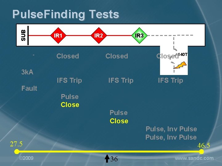
SUB Pulse. Finding Tests IR 1 - Closed IR 2 IR 3 Closed 140 T 3 k. A IFS Trip Fault Pulse Close Pulse, Inv Pulse 27. 5 © 2009 46. 5 36 www. sandc. com
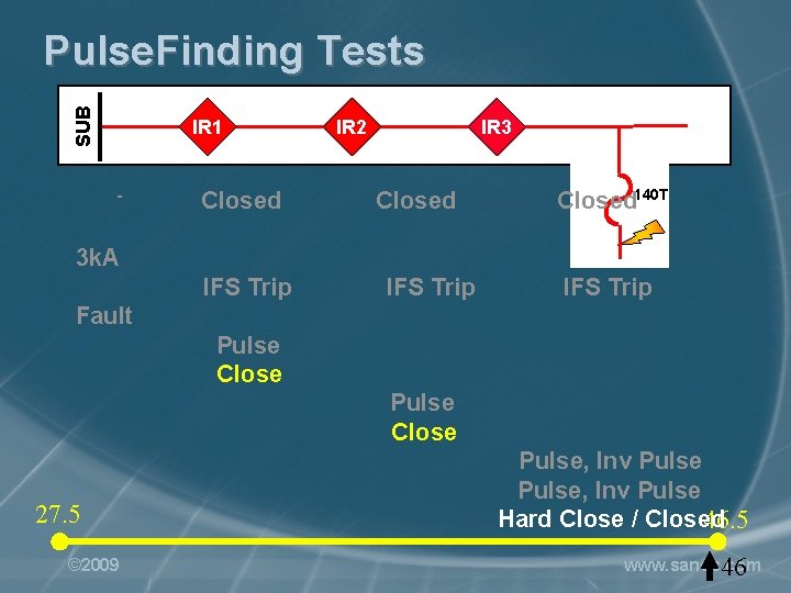
SUB Pulse. Finding Tests IR 1 - Closed IR 2 IR 3 Closed 140 T 3 k. A IFS Trip Fault Pulse Close 27. 5 © 2009 Pulse, Inv Pulse Hard Close / Closed 46. 5 www. sandc. com 46
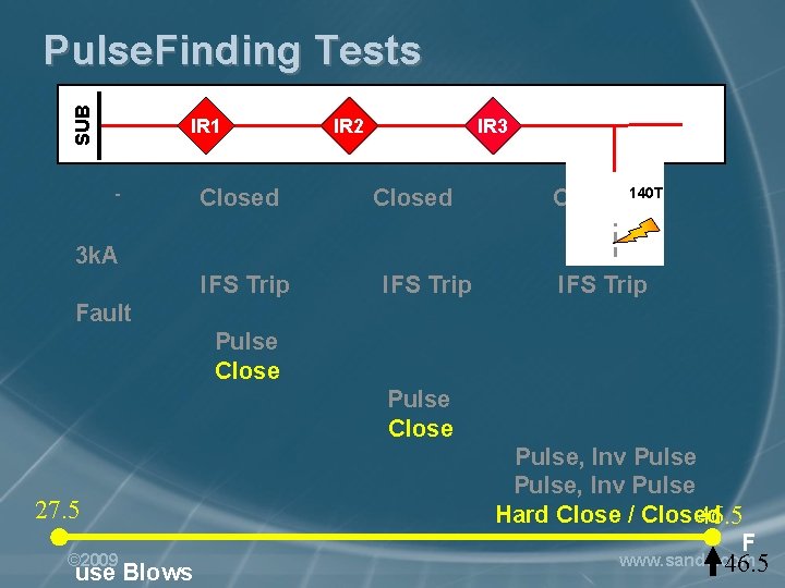
SUB Pulse. Finding Tests IR 1 - Closed IR 2 IR 3 Closed 140 T 3 k. A IFS Trip Fault Pulse Close 27. 5 © 2009 use Blows Pulse, Inv Pulse Hard Close / Closed 46. 5 F www. sandc. com 46. 5

EPRI Pulse. Closer Testing at Hydro-Quebec / IREQ Pulse. Finding Test Video © 2009 www. sandc. com
The Future Distribution System – Key Challenges • Significantly more complex protection due to widespread use of protective devices, DER, changing feeder topology, etc. • Frequent reconfiguration of the power grid • Unpredictable power flow • Islanding © 2009 www. sandc. com
Intelli. TEAM III – Upcoming Features • High Speed Fast Fault Isolation and Restoration • Interface to DMS/SCADA Systems • Precision Curve Fitting • Automatic Protection Setup • Communication Enhanced Coordination • Advanced Adaptive Protection © 2009 www. sandc. com
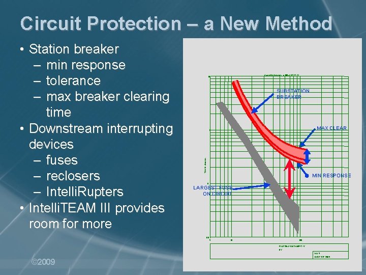
Circuit Protection – a New Method Current in Amperes: x 100 at 12. 47 k. V. 10 SUBSTATION BREAKER MAX CLEAR 1 Time in Seconds • Station breaker – min response – tolerance – max breaker clearing time • Downstream interrupting devices – fuses – reclosers – Intelli. Rupters • Intelli. TEAM III provides room for more MIN RESPONSE 0. 1 LARGEST FUSE ON CIRCUIT 0. 01 5 10 100 PLOTTING VOLTAGE: 12. 47 k. V BY: NO: 5 © 2009 DATE: 5 -27 -2005 www. sandc. com
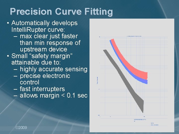
Precision Curve Fitting • Automatically develops Intelli. Rupter curve: – max clear just faster than min response of upstream device • Small “safety margin” attainable due to: – highly accurate sensing – precise electronic control – fast interrupters – allows margin < 0. 1 sec © 2009 www. sandc. com
Automatic Protection Setup • Automatically sets Intelli. Rupter protection curves – no need to change substation breaker relay settings – but may achieve more benefit if breaker settings can be changed • Benefits – simplifies and speeds configuration © 2009 www. sandc. com
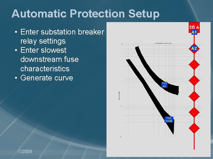
Automatic Protection Setup • Enter substation breaker relay settings • Enter slowest downstream fuse characteristics • Generate curve A 1 A 2 TCC A 1 TCC FUSE © 2009 www. sandc. com
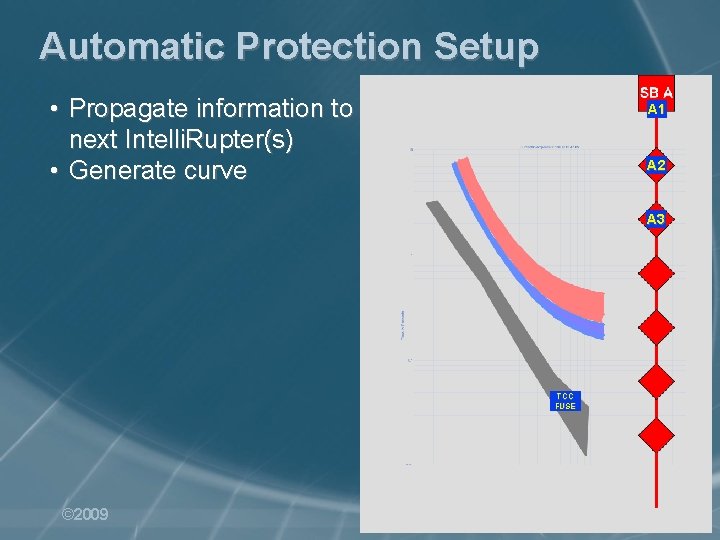
Automatic Protection Setup • Propagate information to next Intelli. Rupter(s) • Generate curve A 1 A 2 A 3 TCC FUSE © 2009 www. sandc. com
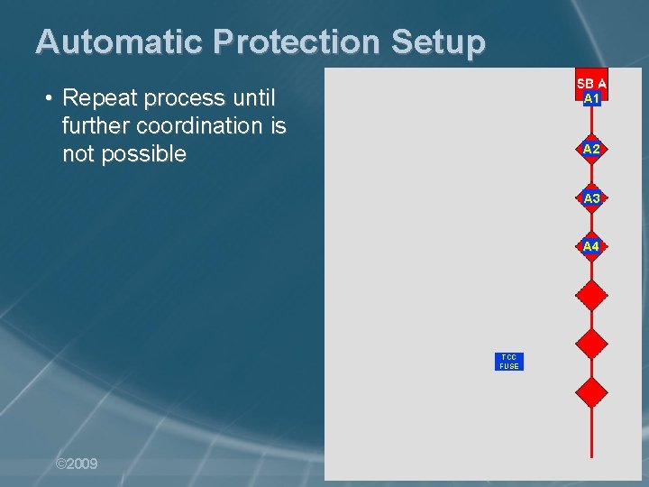
Automatic Protection Setup • Repeat process until further coordination is not possible A 1 A 2 A 3 A 4 TCC FUSE © 2009 www. sandc. com
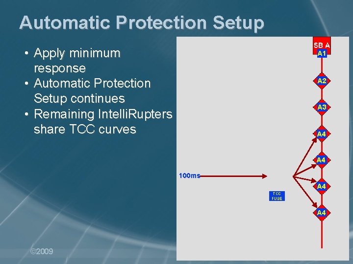
Automatic Protection Setup • Apply minimum response • Automatic Protection Setup continues • Remaining Intelli. Rupters share TCC curves A 1 A 2 A 3 A 4 100 ms A 4 TCC FUSE A 4 © 2009 www. sandc. com
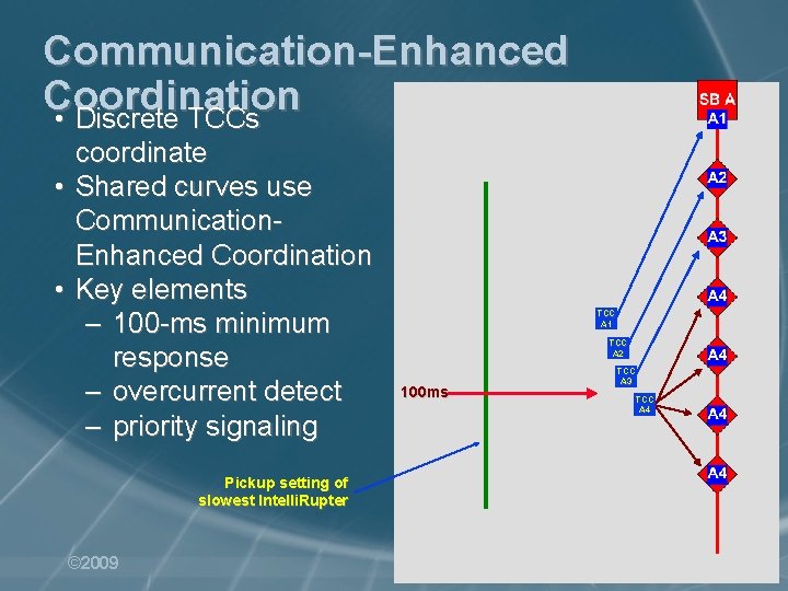
Communication-Enhanced Coordination • Discrete TCCs coordinate • Shared curves use Communication. Enhanced Coordination • Key elements – 100 -ms minimum response – overcurrent detect – priority signaling TCC A 1 TCC A 2 100 ms TCC A 3 TCC A 4 Pickup setting of slowest Intelli. Rupter © 2009 www. sandc. com
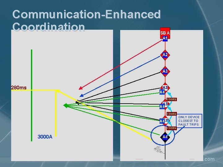
Communication-Enhanced Coordination 280 ms A 4 COORD ONLY DEVICE CLOSEST TO FAULT TRIPS A 4 COORD 3000 A © 2009 www. sandc. com
Communication-Enhanced Coordination • High-speed Speed. Net Radio communication ensures that the proper device opens • Benefits: – install more fault interrupting devices to reduce the impact of outages – isolate problem areas – enhanced service to critical customers – and more benefits will be discovered! © 2009 www. sandc. com
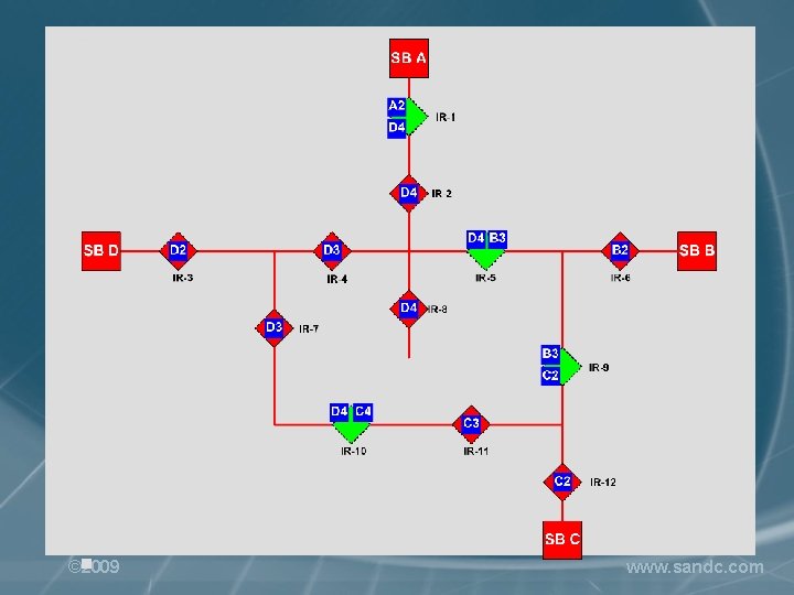
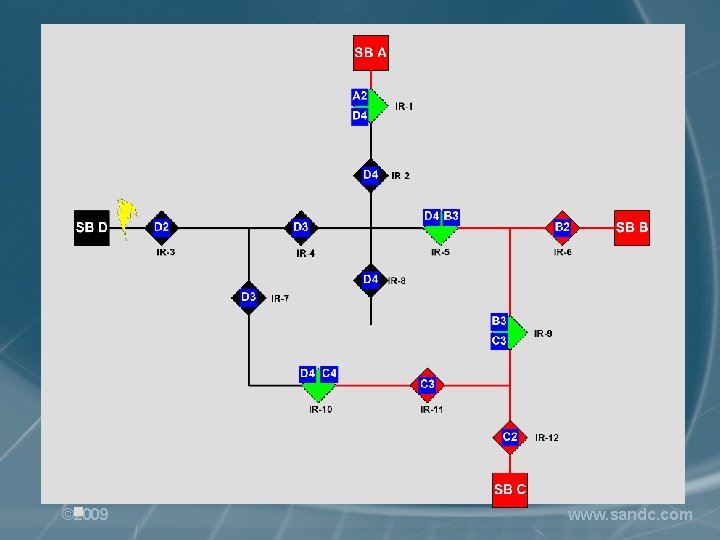
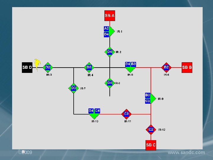
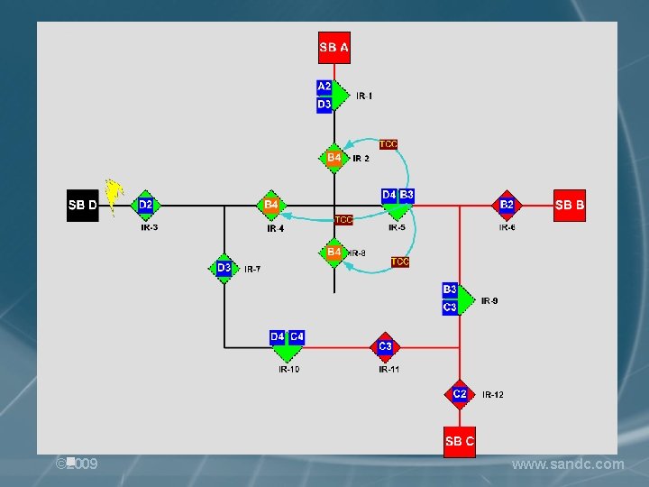
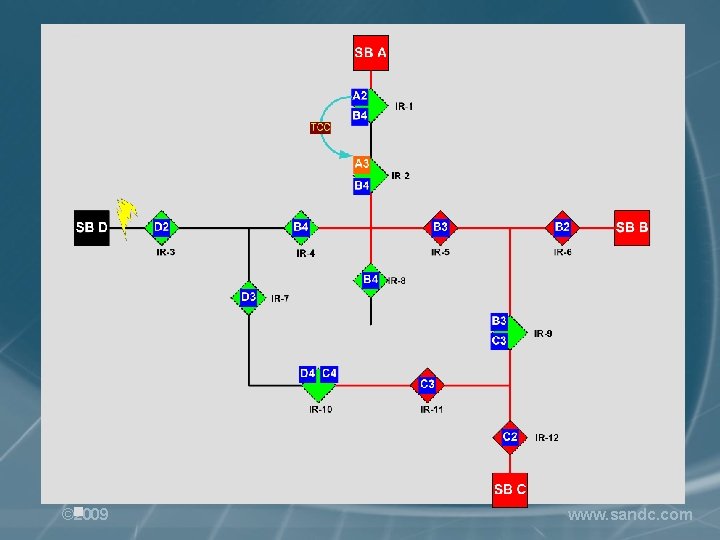
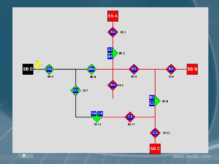
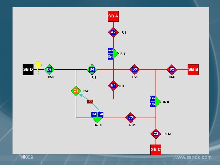
Advanced Adaptive Protection • Automatically reconfigures protection settings after circuit reconfiguration – to re-establish coordination – for any network of circuits • Benefits: – enables complex circuit configurations – enhances circuit planners’ ability to meet their customers’ needs – enables better use of existing assets – no need to re-do protection when the system changes - a huge time-saver! © 2009 www. sandc. com
© 2009 www. sandc. com
© 2009 www. sandc. com
© 2009 www. sandc. com
© 2009 www. sandc. com
© 2009 www. sandc. com
© 2009 www. sandc. com
© 2009 www. sandc. com
© 2009 www. sandc. com
© 2009 www. sandc. com
© 2009 www. sandc. com

Witold Bik VP, Automation Systems Division, S&C Electric Company wbik@sandc. com © 2009 510. 749. 5611 www. sandc. com
- Slides: 66