Savitribai Phule Pune University S E Mechanical Engineering
 Semester-I (2015 Course) Subject Name Manufacturing")
Savitribai Phule Pune University S. E. (Mechanical Engineering) Semester-I (2015 Course) Subject Name Manufacturing Process I

CASTING

CASTING �Casting • • since about 4000 BC… One of the Oldest mfg process. It is the process in which molten metal is poured into the mould or cavity which conforms to the shape of desired component.

TERMINOLOGY OF CASTING

STEPS IN CASTING

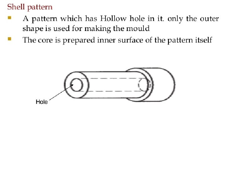
PATTERN MAKING A pattern is a replica of the final product and is used for preparing mould cavity made of wood, metal, Wax, Plastics etc.

Selection of materials for pattern q The number of casting to be made – metal casting preferred for large quantity of production. q Degree of accuracy & quality of surface required on casting. q Method of moulding to be used. q Type of casting method to be used. q Shape & size of casting. q Type of moulding material to be used.

PATTERN MAKING ALLOWANCE A pattern is always made larger than the required size of casting due to metallurgical & mechanical reasons. q Hence some allowances are added to the size of pattern which are: q a. Shrinkage allowance b. Machining allowance c. Draft or taper allowance d. Distortion allowance

A. Shrinkage Allowance When any metal cools and solidifies it shrinks and contracts in size(mm/meter). q The shrinkage allowance of a metal depends on the following factors: 1. The metal to be cast 2. Pouring temperature of molten metal 3. Dimensions of the casting q Steel- 20. 8, Grey Cast Iron-6. 95 -10. 4, Al-16. 5, Brass-15. 5, Bronze -10. 5 -21, Magnesium-16. 5

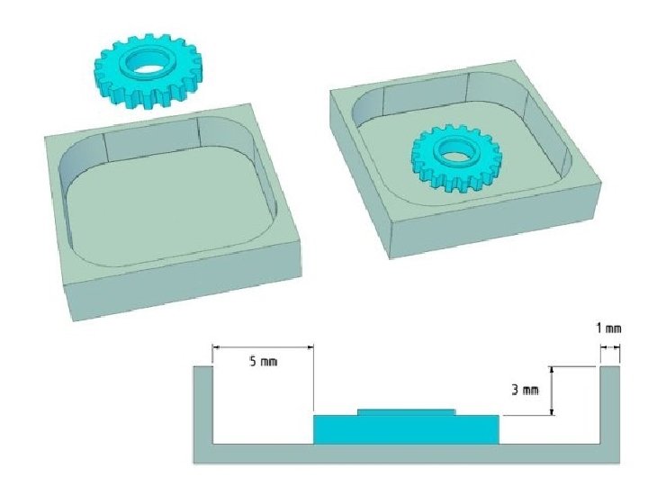
B. Machining Allowance Machining allowance or finish allowance is the amount of dimension on a casting which is made oversized to provide stock for machining. q The amount machining allowance depends upon following factor : q 1. 2. 3. 4. 5. � � � Metal of casting Method of machining to be used Method of casting to be used Size & shape of casting Degree of surface finish required Ferrous metal needs more allowances than non ferrous metals. Large casting need more allowances than Small casting. It varies from 1. 5 to 16 mm, but 3 mm is more common in small & medium casting

C. Draft Or Taper Allowance The slight taper on inward or outward on vertical faces is known as draft. q It can be expressed either in degree or in mm/meter. q It is provided for easy removal of pattern from the sand w/o disturbing the cavity. q. It depends on method of moulding & material of moulding q. It is 10 to 25 mm/meter on external surface & 40 to 65 on internal surface q

C. Draft Or Taper Allowance

D. Distortion Allowance It is provided on odd and irregular shaped objects like U & V bend. q The shape of the pattern is bent in the opposite direction so that after solidification of metal the casting will have a original shape q. It varies from 2 mm to 20 mm as per size, shape & casting material. q

Types Of Pattern The various types of pattern which are commonly used are as follows: 1. Loose Patterns 2. Match Plate Pattern 3. Gated Pattern q

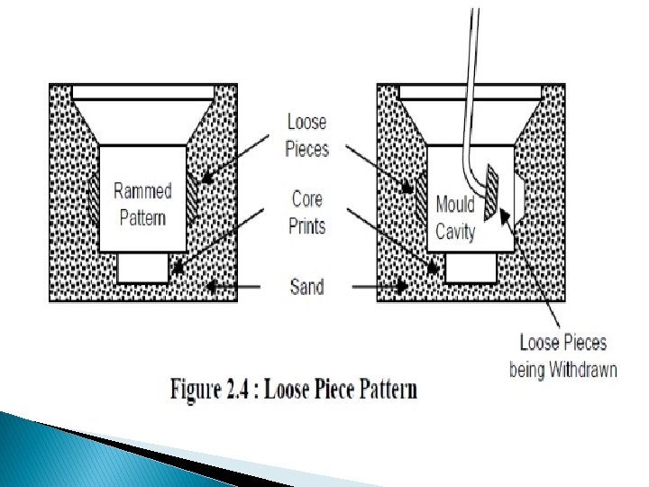
Loose Patterns • Solid Patterns • Self Core Patterns • Loose piece Pattern • Split Pattern

© 2007 John Wiley & Sons, Inc. M P Groover, Fundamentals of Modern Manufacturing 3/e

Single Piece Or Solid Pattern This pattern are made in single piece ( one piece ) without joints. q It is generally used for making large size simple casting. q It is less expensive as compared to other type of pattern. q Used to make stuffing box of steam engine q

© 2007 John Wiley & Sons, Inc. M P Groover, Fundamentals of Modern Manufacturing 3/e

Split Pattern This type of pattern are made in two pieces called as split pattern. ( Due to back Draft) q Its upper part & lower part are accommodated in the cope & drag portion of the mould respectively. q For keeping the alignment between the two parts of the pattern dowels pins are used. q casting of taps & water stop cocks is produced. q Multi Piece Pattern (More than two Patterns & multiple flask) Used to make engine of Ferrari car

Gated Pattern

Match Plate Pattern q When the split patterns are mounted with half on one side of a plate and the other half directly on the opposite side of the plate the pattern is called as match plate pattern

Match Plate Pattern The plate can be made up of wood, aluminum, magnesium or steel. q Match plate pattern are generally used in machine moulding because they produce accurate casting at faster rate. q Used to make Piston Rings of IC engine. q

© 2007 John Wiley & Sons, Inc. M P Groover, Fundamentals of Modern Manufacturing 3/e

Cope and Drag Pattern When large casting are to be made it is desirable to have cope and drag halves of split pattern. These halves are attached to separate match plates q This method helps to increase the production appreciably. q
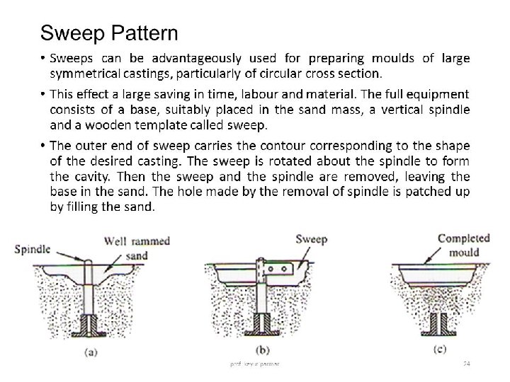

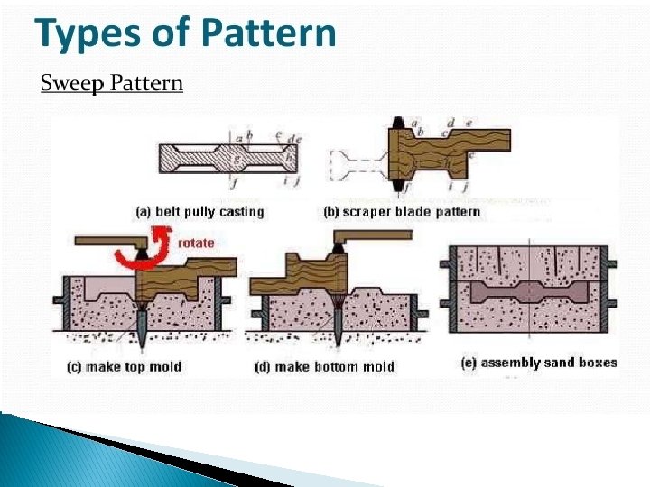
Sweep Pattern
split pattern a)Single piece e) Gated pattern c)match plate pattern")
Types Of Pattern q b)split pattern a)Single piece e) Gated pattern c)match plate pattern d)cope and drag pattern

MOULD MAKING

MOULD MAKING The important part in Mould Making is SAND. q It is because it is inexpensive and has high resistance to temperature. q Course Grain (High Permiability & Low Fine Grain (Low Permiability & High

Silica Sand Grain Texture Sharp edges Size Course Medium Fine
 Silica ( Si. O 2) :")
Principal ingredients of sand q q q 1) Silica ( Si. O 2) : It is granular Form of quartz. It has high softening temp. It possess good thermal stability. 2) Clay : It is a binder material. Moulding sand contains 5 – 10 % clay. 3) Moisture : It furnishes the bonding action of clay. The Moisture content should be between 0 – 2%.
 NATURAL SAND : q It is obtained from")
TYPES OF MOULDING SAND q 1) NATURAL SAND : q It is obtained from river beds, pits or by crushing yellow sandstone. q It can be directly used for making moulds. q It is easily available and has low cost. q It can be used for most ferrous and non - ferrous light casting. q But it is less refractory then other types of sand.
 SYNTHETIC SAND : q It is prepared by")
TYPES OF MOULDING SAND q 2) SYNTHETIC SAND : q It is prepared by adding some ingredients to natural sand(Binder like bentonite). q It is a formulated sand. q It has better properties as compared to natural sand. q It is also suitable for ferrous and nonferrous material. q Its grain size is more uniform than other sands.
 SPECIAL SAND : q GREEN SAND q DRY")
TYPES OF MOULDING SAND q 3) SPECIAL SAND : q GREEN SAND q DRY SAND q LOAM SAND q FACING SAND q BACKING SAND q SYSTEM SAND q PARTING SAND q CORE SAND
 GREEN SAND : q It contains silica, 15")
TYPES OF MOULDING SAND q 1) GREEN SAND : q It contains silica, 15 -25 % Clay, and 6 -8 % water. q It is fine, soft, light and porous. q It is used for small and medium size casting. q Green sand moulds are poured in the green condition.
 DRY SAND : - q When green sand")
TYPES OF MOULDING SAND q 2) DRY SAND : - q When green sand is baked or dried it is called as Dry Sand. q It is suitable for large casting.
 LOAM SAND : q It has high clay")
TYPES OF MOULDING SAND q 3) LOAM SAND : q It has high clay content about 50% or more. q This type of sand dries hard. q It is used for making moulds of heavy and large parts.
 FACING SAND : q It is freshly prepared")
TYPES OF MOULDING SAND q 4) FACING SAND : q It is freshly prepared fine sand, which covers the pattern all around it. q Facing sand forms the face of the mould. q It is subjected to worst condition, hence it has high strength and refractoriness. q. Graphic, plumbago, coke dust sea coal etc added to the facing sand.
 BACKING SAND : q It is used to")
TYPES OF MOULDING SAND q 5) BACKING SAND : q It is used to backup the facing sand. q Old repeatedly used sand is generally employed for this purpose. q It is black in color. q It is the floor sand which can be used again and again.
 SYSTEM SAND : q This type is used")
TYPES OF MOULDING SAND q 6) SYSTEM SAND : q This type is used when machine moulding is applied. q It is cleaned and reactivated by using special additives. q It has good strength, permeability and refractoriness.
 PARTING SAND : q To avoid sticking of")
TYPES OF MOULDING SAND q 7) PARTING SAND : q To avoid sticking of two halves of mould box and sticking of the pattern to mould this sand is sprinkled at parting surface. q Dry silica sand burnt sand are used for this purpose. q. Sea sand is used, Some sands with parting compounds like-charcoal, limestone, talc, calcium phosphate
 CORE SAND : - q This sand is")
TYPES OF MOULDING SAND q 8) CORE SAND : - q This sand is different from moulding sand. q It has high silica content and very low clay content. q Its grain size is large to increase the permeability. q It is used for making core. q. Silica sand is mixed with core oil which composed of linseed oil, resin, light mineral oil & other binding material.
 POROSITY OR PERMEABILITY: Moulding sand should posses porosity to")
PROPERTIES OF MOULDING SAND 1) POROSITY OR PERMEABILITY: Moulding sand should posses porosity to allow gases, moisture, steam etc. generated within the mould to be removed freely when the molten metal is poured in mould box. 2) FLOWABILITY : It is the ability of the moulding sand to behave like fluid. Flowability increases as clay and water content increases.
 ADHESIVENESS : The sand particles must be capable of")
PROPERTIES OF MOULDING SAND 3) ADHESIVENESS : The sand particles must be capable of adhering to the surface of another body i. e; they should stick to the sides of moulding boxes. 4) COHESIVENESS : It is the ability of the sand particles to stick together. This property of sand in green or moist state is called as Strength.
 REFRACTORINESS : The moulding sand must be able to")
PROPERTIES OF MOULDING SAND 5) REFRACTORINESS : The moulding sand must be able to withstand the high temperature of molten metal without fusing. This property is called as Refractoriness. If sand lacks this property then smooth casting surface cannot be obtained. 6)COLLAPSIBILITY 7) THERMAL STABILITY

STEPS IN MOULD MAKING 1. Select suitable moulding board, moulding box, Riser & Gating system.

STEPS IN MOULD MAKING 2. Place drag half of the box on the moulding board with aligned pins pointing downward

STEPS IN MOULD MAKING 3. Place drag pattern with parting surface down on the bottom board

STEPS IN MOULD MAKING 4. Sprinkle the facing sand all around the pattern.

STEPS IN MOULD MAKING 5. Fill the drag half with moulding sand.

STEPS IN MOULD MAKING 6. Invert the drag half of moulding box on moulding board so that aligned pin is pointing upward.

STEPS IN MOULD MAKING 7. Place the cope pattern on the drag pattern.

STEPS IN MOULD MAKING 8. Place cope half over the rammed drag half & aligned them by using dowel pins.

STEPS IN MOULD MAKING 9. Place sprue & riser pins to form suitable size cavities for molten metal pouring.

STEPS IN MOULD MAKING 10. Sprinkle the facing sand all around the cope pattern.

STEPS IN MOULD MAKING 11. Fill the cope with sand & ram it.

STEPS IN MOULD MAKING 12. Remove the sprue & riser pins.

STEPS IN MOULD MAKING 13. Remove both cope & drag pattern & repair the mould if necessary.

STEPS IN MOULD MAKING 14. Cut the gate connecting the sprue with mould cavity.

STEPS IN MOULD MAKING 15. In case of dry sand mould bake the mould.

STEPS IN MOULD MAKING 16. Close the moulding box and Finally clamp the cope with drag & mould is ready for pouring.

Additives Coal Dust – Used in sand for grey cast iron casting. It reduces cohesiveness and strength of sand Sea coal- Finely ground soft coal-improves surface finish-reduces hot strength & permeability. Cornflour or cerels(0. 25 -2%)-improves strength, toughness & collapsibility- reduces permeability & flowability.
- reduces expansion defectincreases collapsibility surface finish & thermal")
Additives � Wood flour(0. 5 -2%)- reduces expansion defectincreases collapsibility surface finish & thermal Stability � Pitch(2%)- Increases hot strength & surface finish on ferrous casting. If added more then reduces green strength. � Water(1. 5 -8%) – Amount of water is partly absorbed by clay & remaining water is known as free water. Free water act as lubricant & improves plasticity, mouldability-reduces strength.

Sand testing a. b. c. d. Moisture content test Clay content test Compression strength test Permeability test

Moisture Content Test Moisture Determining Apparatus

Clay Content Test Procedure- Take the Sample of 50 gm. of dry sand , Dried it at 105 c for hour & place it in the wash bottle add 475 ml distilled water, 2. 5 -3% sodium hydroxide or caustic soda. Stir the mix for 5 min. fill the bottle up to mark, wait for 10 min the sand get settled. Remove the dirty water and fill the bottle again and repeat the procedure. After getting the clean sand dry it & measure its weight.

Compressive Strength Test

Permeability Test Permeability no. = (V*

Core, Core Prints & Core Box © 2007 John Wiley & Sons, Inc. M P Groover, Fundamentals of Modern Manufacturing 3/e

© 2007 John Wiley & Sons, Inc. M P Groover, Fundamentals of Modern Manufacturing 3/e

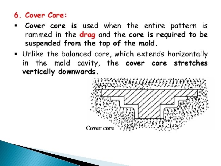
Types Of Core According to shapes & positions in the prepared mould the cores can be classified as 1) Horizontal core 2) Vertical core 3) Balanced core 4) Drop core

© 2007 John Wiley & Sons, Inc. M P Groover, Fundamentals of Modern Manufacturing 3/e

© 2007 John Wiley & Sons, Inc. M P Groover, Fundamentals of Modern Manufacturing 3/e

Balanced core Drop core

© 2007 John Wiley & Sons, Inc. M P Groover, Fundamentals of Modern Manufacturing 3/e

Core ØCore making 1. Core sand preparation-sand, 1% core oil, 1% cereal, 2. 5 -65 water(low clay & course grain size). Binders-Organic( core oil, pitch, synthetic resin), Inorganic(fire clay, bentonite, iron oxide), other binders(cement, sodium silicate), water Core making -Hand Rammed / Machine 2. 3. Core Baking – Baked using oven 4. Core finishing – By rubbing & filing 5. Setting the cores – Positioned accurately

Gating System

Pouring Cups

Sprue ØIt may be Rectangular & Round in shape. Ø 20 mm diam. – Round in section ØLarger sprues – Rectangular

Runner

Gate

Types Of Gate 1. Parting line gates 2. Top gates 3. Bottom gates 4. Side gates

1. Parting Line Gates

2. Top Gates / Drop Gates Ø Lot of turbulence in this system Ø Dropping of liquid metal stream erodes the mould surface.

3. Bottom Gates Advantages Ø It provide less turbulence & erosion in the mould cavity.

4. Side Gates It is provided on either left or right side of casting. Hence the molten metal enters in to the mould cavity from sides.

Riser Functions Ø It permits the escape of Air & Mould gases. Ø It indicates that the mould cavity has been completely filled or not.

Types of Riser 1. Open riser 2. Blind riser

1. Open Riser

2. Blind Riser

Design of Riser 1. Shape Of Riser: Cylindrical Height of cylindrical riser = 1. 5 x diam. of Riser

2. Size Of Riser Ø 1. By Chvorinovs Rule : - Solidification time (freezing time) : - t α (V/A)2 2 t = C (V/A) Where t – Solidification time in sec. V – Volume of casting in m 3 A- Surface Area in m 2 C – constant which depends upon the mould material & the metal to be cast.
 Freezing ratio (X) : (A/V)")
2. Size Of Riser 2. Caine’s rule : i) Freezing ratio (X) : (A/V) X =Casting _______ (A/V) Riser ii) Volume ratio (Y) : Vcasting Y= _______ Vriser

Moulding Machines • Squeeze Moulding Machine • Jolt- Squeezing Moulding Machine • Sand Slinger Moulding Machine

Squeeze Moulding Machine

Jolt Moulding Machine

Jolt- Squeezing Moulding Machine

Sand Slinger Moulding Machine
 a. permanent")
CASTING PROCESSES 1. Sand mould casting 2. Metallic mould casting (Die casting) a. permanent mould casting b. pressure die casting 3. Investment casting 4. Centrifugal casting 5. Continuous casting

DIE CASTING PROCESSES This process is particularly suitable for lead, magnesium, tin, zinc alloys, aluminum and brass. It is classified into two types: A. Permanent mould casting B. Pressure die casting
 Mould is preheated and coated.")
A. Permanent mould casting 1) Mould is preheated and coated.
 Cores (if used) are inserted and mould is closed,")
A. Permanent mould casting 2) Cores (if used) are inserted and mould is closed,
 Molten metal is poured into the mould, where it")
A. Permanent mould casting 3) Molten metal is poured into the mould, where it solidifies.
 Mould is opened.")
A. Permanent mould casting 4) Mould is opened.

A. Permanent mould casting 5. Remove the casting from mould.

A. Permanent mould casting 6. Final Casting.

A. Permanent mould casting

B. Pressure Die Casting In pressure die casting molten metal is poured by pressure (70 to 5000 kg/cm 2) into a metal mould known as die. The main types of die casting machine are: 1. Hot chamber die casting 2. Cold chamber die casting

1. Hot Chamber Die Casting

1. Hot Chamber Die Casting
")
1. Hot Chamber Die Casting (zinc tin & lead )
")
2. Cold Chamber Die Casting (Mg, Al & Brass)

2. Cold Chamber Die Casting

2. Cold Chamber Die Casting

Advantages Of Die Casting 1. 2. 3. 4. 5. 6. Very high rate of production Close dimensional accuracy Good surface finish Unit cost is minimum Less floor space is required Longer die life

Disadvantages Of Die Casting 1. Only economical for non-ferrous alloys. 2. Heavy casting cannot be cast 3. Initial cost is high 4. Casting by this method usually have porosity problem

Disadvantages Of Die Casting 1. Only economical for non-ferrous alloys. 2. Heavy casting cannot be cast 3. Initial cost is high 4. Casting by this method usually have porosity problem

800 ton hot chamber die casting machine, DAM 8005. This is the largest hot chamber machine in the world and costs about $1. 25 million.
 It is a very old process generally used")
3. Investment casting (Lost wax process) It is a very old process generally used by dentist and jewelers for a no of years. This process uses expendable patterns (wax patterns) to form a cavity for the casting. This process gives very smooth and highly accurate casting.
 Wax patterns are produced,")
Steps in investment casting (1) Wax patterns are produced,
 Several patterns are attached to a sprue to form")
Steps in investment casting 2) Several patterns are attached to a sprue to form a pattern tree
 The pattern tree is coated with a thin layer")
Steps in investment casting (3) The pattern tree is coated with a thin layer of refractory (325 mesh silica floursuspended in ethyl silica solutution) material.
 The full mould is formed by covering the coated")
Steps in investment casting 4) The full mould is formed by covering the coated tree with sufficient refractory material to make it rigid.
 The mould is held in an inverted position and")
Steps in investment casting 5) The mould is held in an inverted position and heated to melt the wax and permit it to drip out of the cavity.
 The mould is preheated to a high temperature to")
Steps in investment casting (6) The mould is preheated to a high temperature to make it hard & dry, after that the molten metal is poured, and it solidifies
Aftersolidification, the mould is broken away from the finished casting")
Steps in investment casting (7)Aftersolidification, the mould is broken away from the finished casting and the parts are separated from the sprue.

Steps in investment casting FINAL CASTING

4. Centrifugal Casting In this method, molten metal is poured at the center of a rotating mould. Due to rotation a centrifugal force acts on a liquid and pushes it towards the mould walls where it remains until it cools and solidifies into some form of hollow product.
 Types of Centrifugal Casting Processes: 1. True Centrifugal Casting")
4. Centrifugal Casting (Liquid forging) Types of Centrifugal Casting Processes: 1. True Centrifugal Casting 2. Semi- Centrifugal Casting 3. Centrifuging

1. True Centrifugal Casting

1. True Centrifugal Casting

2. Semi- Centrifugal Casting

2. Semi- Centrifugal Casting

2. Semi- Centrifugal Casting

3. Centrifuging

Advantages of centrifugal Casting 1. Mechanical Properties are superior. 2. The process is more economical than other methods. 3. Wide variety produced. of objects can be 4. Centrifugally cast pipes have a high resistance to atmospheric corrosion.

Disadvantages Of Centrifugal Casting 1. Method is not applicable to some alloys. 2. Limitation on size and shape of objects.

4. Continuous Casting

4. Continuous Casting

Defects and Remedies in Casting defects are usually not a accidents, they occur because some manufacturing steps are not properly controlled.

Defects and Remedies in � 1. Blow holes Casting Blow hole appears as cavities in a casting. Ø Possible 1. 2. 3. causes Excess moisture content in the sand moulding Cores are not sufficiently baked Improper Ventilation ØEffective remedies 1. 2. 3. 4. 5. Control moisture content Bake the cores properly Permeability of sand must be properly controlled Provide Proper Ventilation Do not ram too hard

1. Defects and Remedies in Casting Blow holes : -

� 2. Defects and Remedies in Casting Pin hole Porosity : - This are small gas cavities less than 2 mm visible on the surface of casting, occur due to gases absorbed by molten metals like oxygen, hydrogen & nitrogen �Possible 1. 2. High temp of pouring Slow solidification �Effective 1. 2. 3. causes remedies Regulate pouring temp Increase solidification rate Reducing moisture content.
 : -")
2. Defects and Remedies in Casting Porosity (Pinholes) : -
 Defects and Remedies in Casting Shrinkage: - It is depression in the")
� 3) Defects and Remedies in Casting Shrinkage: - It is depression in the casting. �Possible causes 1. 2. Faulty gating & riser design. uncontrolled solidification. § Effective remedies 1. Modifying gating & riser design. 2. Achieving directional solidification.

3. Defects and Remedies in Casting Shrinkage: -

Defects and Remedies in Casting 4. Misrun & cold shuts : - 1. Molten metal fails to reach all sections of the mould 2. Certain part of mold remains unfilled 3. Result in an incomplete casting Possible Causes: - 1. Pouring temp. too low 2. C/s of cavity too thin. Effective remedies: - 1. Modify design 2. Increase molten metal fluidity.

Defects and Remedies in Casting 4. Misrun & Cold Shuts : -
 : - Shift is a misalignment")
Defects and Remedies in Casting 5. Mismatch (Shift) : - Shift is a misalignment between two mating surface usually at the parting line. Effective remedies: 1. Use of dowel pins for aligning the pattern.
 : -")
Defects and Remedies in Casting 5. Mismatch (Shift) : -

Defects and Remedies in Casting 6. Penetration : - This defect occurs as rough surface of casting. Possible Causes: 1. High Fluidity of molten Metal Effective Remedies: 1. Reduce Fluidity of metal.

Bent or twisted casting- internal stresses, nonuniform solidification. Provide ribs, allowances for pattern Dropped mould – uneven ramming, low green strength. Do proper ramming Fusion – Low refractoriness, poor quality facing sand. Provide low pouring temp. & Use sand of high refractoriness. Swell – bulging of casting due to liquid metal pressure, poor ramming. Do proper ramming Core Shift- improper support, Provide correct alignment Inclusion- Dirt, oxide, slag, sand. Proper gating system with low turbulence Hot tears- Irregular internal & external cracks occurs after solidification. It occur on casting having abrupt section changes. Use dorectional solidification, proper casting & Gating design

Note • All the above content of these PPTs were taken from PPTS of renown author via Personal/Internet, only some additional data is added by me. • These PPTs are only mean to share the knowledge among the Students. • I specially thanks to the authors and owner due to whom it is possible to prepare these PPTs.
- Slides: 158