SAS TRD p spinelli CERN 210215 Possible TRD

SAS TRD p. spinelli CERN 2/10/215 Possible TRD configurations for PID up to the Te. Vs energies fig. s for this talk taken by: B. Dolgoshein Transition radiation detectors -NIM A 326(1993) N. Giglietto, C. Favuzzi, M. N. Mazziotta and P. Spinelli Transition radiation detectors for particle physics and astrophysics -Nuovo Cimento 5 -6 (2001) 1. Some history (I hope not too much, but it is necessary) 2. Conventional configurations : what problems ? 3. An almost unconventional idea: but not yet proved…

thresholds for TR emission g TH= 2. 5 d 1 wp TR saturation g TH= 1. 2 g TH (d 2/ d 2)1/2 Slower particle pulse heights In TRDs the faster radiating particle emits TR, observed as a pulse height distribution in the detector overcoming that of the slower one

The TR thresholds for e/p pairs are really far apart ! not the same for p/k or k/p pairs…

Harris et al. 1971 p. h. distributions are skewed! 90% electron acceptance 90% cut on electron distribution particle to identify a few % pion contamination particle to reject
 6% @90% pions")
Better averaging on more sets e. g. 4 sets (5 Gev/c) 6% @90% pions electrons 4% @90% 2% @90% Likelihood technique improves performances

Cluster counting method Dolgoshein, Fabjan et al. 1981 the distributions become nearly poissonian !! therefore : 1% @ 90% acceptance means ≈ 3. 6 s 0. 1% means ≈ 4. 4 s
 8 sets L = 70 cm The best")
Dolgoshein et al. HELIOS TRD (1986) 8 sets L = 70 cm The best so far… << 10 -3

good pion/electron separation better than 10 -3 but what about pion/kaon/proton identification?
 20 modules (Mylar-Xe) L= 3. 5 m What about")
European Hybrid Spectometer CERN (1980) 20 modules (Mylar-Xe) L= 3. 5 m What about p/p or p/k separation ? average over 20 modules

… a few % contamination @ 90% acceptance for any pair, but note: no k/p separation quoted…

what Dolgoshein did in 1981 with cluster counting?

≈ 5% p contamination into K sample but with just L ≈ 70 cm !

p/k becomes ≈ 1% with 24 sets, L = 1. 32 m but note: k/p separation is not quoted … What happened later at higher energies?
 @ 250 Ge. V/c p contamination")
≈ 2 clusters Fermilab E 715 (1983 ) @ 250 Ge. V/c p contamination = 6. 10 -4 @ 92. 5% e- acceptance - 12 sets - L=3. 6 m
 24 sets - L = 2. 79")
Fermilab E 769 @250 Ge. V (1991) 24 sets - L = 2. 79 m p contamination =2% @ 87% p acceptance simulation at @ 500 Ge. V/c k(2%) p (98%) p contamination = 3% @ 90% k acceptance k/p separation ability not quoted… kaons pions
 CERN NA 57 Bari Group")
16 sets TRD for PID (p/p @280 Ge. V) CERN NA 57 Bari Group very compact , L= 90 cm radiator C-fibers straw tube detector p contamination = 1% @ 90% p acceptance read out electronics

Possible TRD configurations for PID up to the Te. Vs energies three configurations based on polyethylene radiators: 100 -200 foils 15 m - 300 m gap 100 -200 foils 50 m - 1 mm gap 100 -200 foils 100 m - 2 mm gap detectors: gaseous or solid state (see next talk) We discuss their PID capability (with a naive procedure ) e. g. starting from 100 TR photons (clusters) collected on the average at saturation; then: MC simulation, Poisson distribution assumed for photons, rejection calculation

from our MC …some normalization problems : I think we over-estimate the TR photons at saturation for thicker radiators

- 200 ? -we assume that the collected photons are ≈ 2 per TRD set at best we need 50 sets ( each with 200 foils radiator) to get 100 TR photons

- 200 ? The thresholds move to higher energies we assume that the collected photons are ≈2 per TRD set at best

- 200 ? The TR thresholds still move at higher energies The proton shows up at 1 Te. V and saturates at 5 Te. V we assume that the collected photons are ≈2 per TRD set at best

Can we roughly estimate the PID capabilities in a simple way? naively by means of the cluster counting method

k/p separation at 1 Te. V - 50 TRD sets 15 m radiator configuration proton Kaon total cluster number proton contamination ≈10 -5 90% acceptance cut
 + 16 sets TRD (50 m) +")
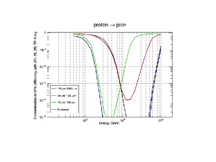
10 -3 16 sets TRD (15 m) + 16 sets TRD (50 m) + 16 sets TRD (100 m) very good (<< 10 -3) p/p separation in the 0. 2 -5 Te. V range
 p/k separation in the 0. 2 -2.")
10 -3 very good (<< 10 -3) p/k separation in the 0. 2 -2. 5 Te. V range

10 -2 Poor K/p separation ≈ 2 % at best in the 1 - 3. 5 Te. V range …but
 L")
15 m TRD – 16 x (6 cm radiator + 2 cm Xe) L = 1. 3 m (0. 17 X 0 , 0. 08 l. I) 50 m TRD – 16 x (20 cm radiator + 5 cm Kr ? ) L = 4 m (0. 56 X 0 , 0. 26 l. I) 100 m TRD – 16 x (40 cm radiator + 10 cm Xe? ) L = 8 m (1. 15 X 0 , 0. 55 l. I) namely L tot = 13, 3 m – 1. 88 X 0 – 0. 9 l. I …huge and heavy TRD like a pre-shower detector! poor k/p separation if we choose a 12 + 48 configuration

still good p/p separation in the 0. 2 - 5 Te. V range

still good p/k separation in the 0. 25 -3 Te. V range

no encouraging change: we get now 2% at best at 5

Conclusions…. Every configuration is “almost -conventional” but poses some serious problems: -on the detectors : thick gaseous (kripton or xenon gas) or solid state (silicon)? see next talk -on the performances: adequate k/p separation is never achieved at most energies -on the layout: too long configurations and too high radiation and interaction lengths !! Unless we apply to an old idea of Boris Dolgoshein…

M. Deutschmann et al. Partice identification using the angular distribution of transition radiation N. I. M. 180 (1981) 409 -412 q≈ 1/g Dx ≈ 0. 1 -1 mm for g = 10. 000 -1000 beware: q mult. scatt. ? 50 -70 cm Single surface g = 6000 Single foil g = 2000

Regular radiator - 50 foils g =1000 The TR photon angular distribution exhibts sharp peaks around q = 1/g because of interfering effects (from theory!!) (note: Coulomb scattering is ≈1 mrad for Te. V hadrons << TR angle )

Pions and electrons @ 3. 5 Ge. V detected in two drift chamber at 50 cm distance from the radiator. Note: most of the hit smearing in both cases is due to multiple scattering (10 times greater than TR angle)

Can we envisage a “miniaturized” ring imaging TRD = RITRD? now we have more advanced pixel detectors ! (see next talk) -we can collect with 10 sets radiator/pixel detector ≈ 20 TR photons (better than a conventional RICH) to overlay on a unique frame to reconstruct a ring -conventional 15 m foil radiators to let any hadron to radiate + 1 m “espansion distance” in helium L ≈ 10 m, still long, but X 0 and l. I will be negligible! -pixel size 50 m x 50 m? (spatial resolution optimized by centroid calculation) -the momenta , namely the rings radii per each kind of particle, are fixed by the calorimeter: at 1 m of espansion distance Rp = 1 mm @ g= 1000 (1 Te. V proton) or Rk = 0. 5 mm @ g= 2000 (1 Te. V kaon)
 Now we separate")
3 Te. V Kaon - proton angular separation (10 TRD sets) Now we separate angular distributions instead of cluster distributions

5 sets, L = 5, 3 m, Rp/k 15%

10 sets, L = 10. 6 m, Rp/k 2. 5%

15 sets, L = 16 m Rp/k 0. 3%

final conclusions We need to explore with appropriate MC calculation the performances of these solutions (see nex talk) We need to carry out real tests on a beam asap


we assume 100 TR photons at saturation 10 -3 contamination 500 Ge. V - 5 Te. V : good separation (<< 10 -3 rejection) for p/k and p/p poor separation of k /p (restricted just at 4 -5 Te. V ≈ 10 -3 rejection) if we take 50 sets, each 40 cm + 10 cm (Xe), L = 25 m (note: 2. 5 X 0, 1. 5 l. I)

Still good p/p separatio

we assume 100 TR photons at saturation 10 -3 contamination 100 Ge. V - 1 Te. V : good separation (<< 10 -3 rejection) for p/k and p/p poor separation of k/p (restricted just at 0. 5 -1. 2 Te. V ≤ 10 -3 rejection) if we take 50 sets, each : 6 cm +1, 5 cm Xe L = 3. 75 m (note: 0. 5 X 0 , 0. 25 l. I)

we assume 100 TR photons at saturation 10 -3 contamination good separation (<< 10 -3 rejection) for p/k (0. 3 Te. V - 2. 5 Te. V) and p/p (0. 3 Te. V- 5 Te. V) poor separation for k/p (restricted just at 2. 5 - 4 Te. V ≤ 10 -3 rejection) if we take 50 sets, each : 20 cm + 5 cm Kr L = 12. 5 m (note: 1. 25 X 0 , 0. 75 l. I)

The p/k separation is problematic at 10 -3
- Slides: 47