SAFETY AND LOSS PREVENTION PTT 351 SOURCE MODEL


- Slides: 36
SAFETY AND LOSS PREVENTION PTT 351 SOURCE MODEL Mohd Sharizan Md Sarip
INTRODUCTION �Most accidents in chemical plants result in spills of toxic, flammable and explosive materials. �Accidents begin with an incident, which usually results in the loss of containment of material from the process. �The material has hazardous properties, that might include toxic properties and energy content.
�Typical incidents might include the rupture or break of a pipeline, a hole in a tank or pipe, runaway reaction or fire external to the vessel. �Once the incident is known, source models are selected to describe how materials are discharged from the process.
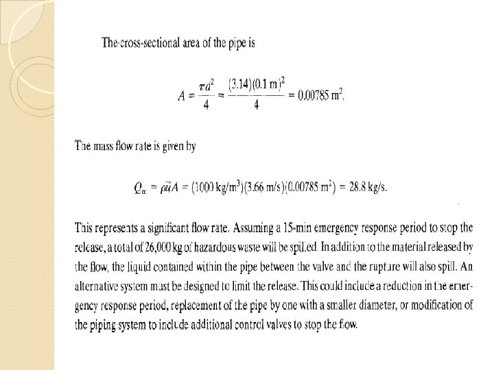
What are source models? �Constructed from fundamental/empirical equation representing the physicochemical process occurring during release of materials. �Sometimes, original models are modified to fit the specific situation �Only can be applied once the incident has been identified �Provide technical information; v Rate of discharge v Total quantity discharged v State of discharge �Release mechanisms are classified into wide and limited aperture (hole/gap) releases.
Mode of release Wide aperture release -Large hole develops in process unit -Releasing a large amount of material in a short period of time Limited aperture release slow release of material that causing non immediate effect to upstream conditions Example: overpressure explosion, explosion of a storage tank Example: leaks in flanges, valves and pumps; ruptured pipes, cracks and relief system
Limited Aperture Release
Basic Source Models Flow of liquid through a hole Flow of liquids through pipes Flow of gases or vapor through holes Flow of gases or vapor through pipes Flashing liquids Liquid pool evaporation or boiling
Flow of liquid through a hole A mechanical energy balance describes the various energy forms associated with flowing fluids: P ū α g gc z F Ws pressure (force/area) density (volume/mass) average velocity of the fluid (length/time) velocity correction factor, dimensionless acceleration due to gravity (length/time 2) gravitational constant (length mass/force time 2) height above datum (length) net frictional loss (length force/mass) shaft work (force length) mass flow rate (mass/time)
Liquid flowing through a hole Liquid pressurized within process unit P = Pg ū 1 = 0 ∆z = 0 Ws = 0 = liquid density Co = Discharge coefficient External surroundings P = 1 atm ū 2 = ū A = leakage area
Discharge Coefficient Value Event Sharp-edged orifices, Re > 30, 000 Co 0. 61 Well-rounded nozzle ~1. 0 Short section pipe attached to a vessel (L: D 3) Unknown/uncertain 0. 81 1. 0
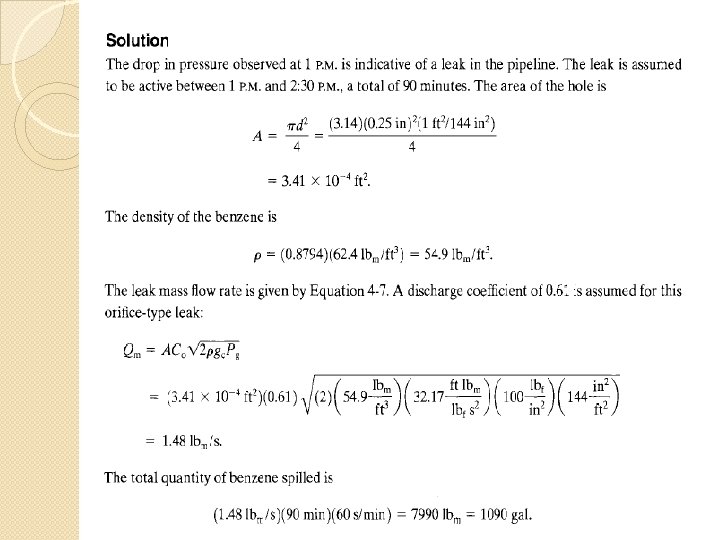
Example 4. 1 At 1 pm the plant operator notices a drop in pressure in a pipeline transporting benzene. The pressure is immediately restored to 100 psig. At 2. 30 pm a ¼ in diameter leak is found in the pipeline and immediately repaired. Estimate the total amount of benzene spilled. The specific gravity of benzene is 0. 8794. A discharge coefficient is assumed as the orifice type leak.
Unit for g and gc Unit SI English Gravitational constant, gc Acceleration due to gravity, g
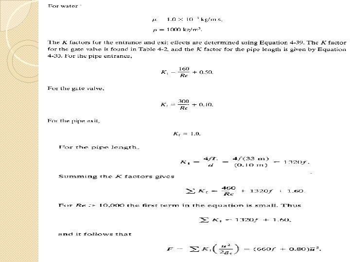
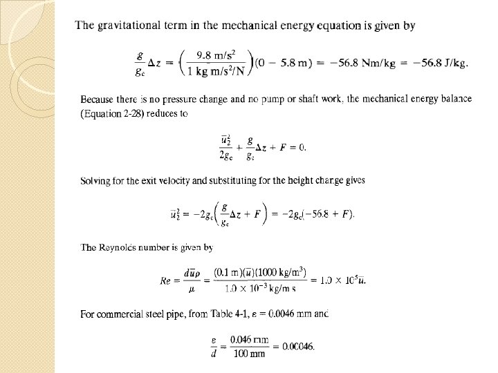
Flow of liquid through pipes Mechanical energy balance for the flow of incompressible liquids through pipes, (density is constant)
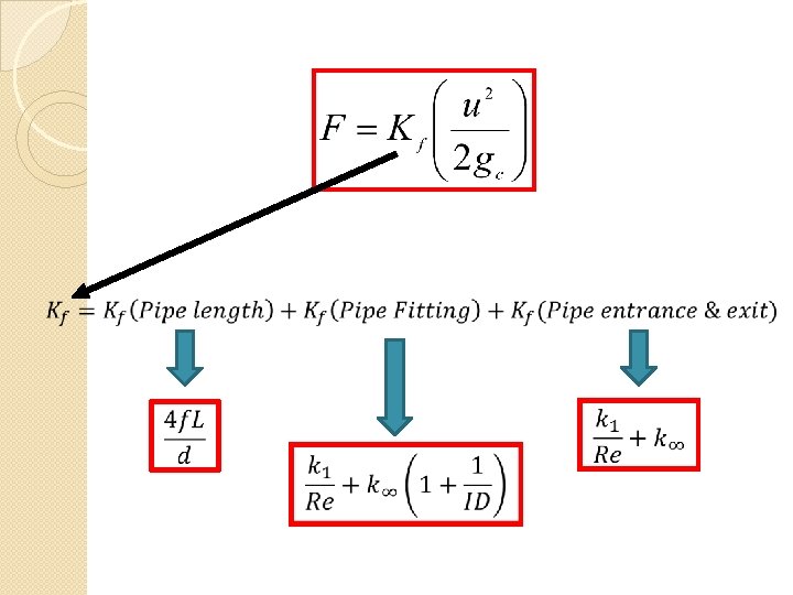
Kf = excess head loss due to the pipe/fitting, dimensionless U = fluid velocity (length/time) The frictional loss, F represent the loss of mechanical energy resulting from friction. Loss of friction includes: ØLoss from flow through length of pipe ØFitting, such as valve, elbows, orifice ØPipe entrances and exits
Loss from flow through length of pipe For fluids flowing through pipes the excess head loss, Kf f fanning friction factor, dimensionless L flow path length d flow path diameter
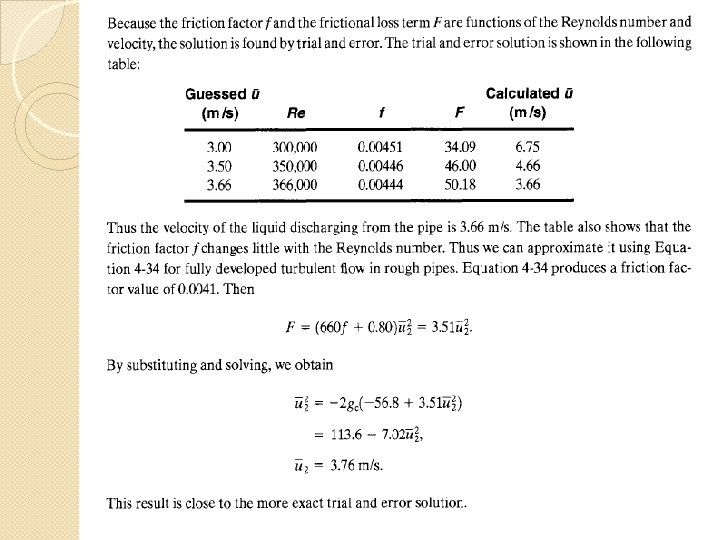
Fanning Friction Factor, f • Fanning friction factor can be obtained via formulas and graph. Flow conditions Fanning Friction Factor, f Laminar flow (Re ≤ 2300) Fully developed turbulent Entire range of Re
Fanning Friction Factor: The chart
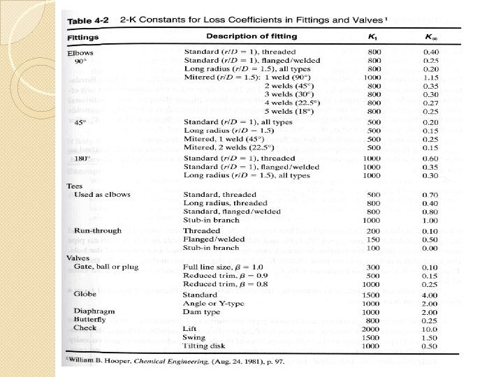
Determination of Kf for Pipe Fittings, Entrance and Exit The Kf for pipe fittings (valves, elbow, tee and other flow obstructions), pipe entrance and pipe exit are determined using 2 -K method for pipe fittings K 1 & K∞ = 2 -K constants for loss coefficient ID = internal diameter ** The values of K 1 & K∞ can be obtained from table
Equa. 10 is modified to estimate the Kf of pipe entrance and exit 2 -K method for pipe entrance/exit Borda-type pipe connection
Example 4. 2
Flow of Gases or Vapors through Holes • The flow of gases or vapors through hole can be classified into throttling and free expansion release. • However, in this chapter, only free expansion release will be considered. • The free expansion release of gases or vapors can be well represented by isentropic expansion.
Flow of Gases or Vapors through Holes Qm is the mass flow rate at any point during the isentropic expansion
Flow of Gases or Vapors through Holes Qm is the mass flow rate at any point during the isentropic expansion The velocity is NOT the maximum velocity. Therefore Qm is NOT the maximum flow rate.
Flow of Gases or Vapors through Holes • For many safety studies, the flow of vapor through hole occurs at maximum flow rate. • The maximum flow rate occurs at maximum downstream pressure which is known as choked pressure, Pchocked. Downstream pressure < P , chocked the following statements are valid: 1. The velocity at the throat of the leak is the velocity of sound. 2. The velocity and mass flow rate cannot be increased further by reducing the downstream pressure; they are in dependent of the downstream conditions.
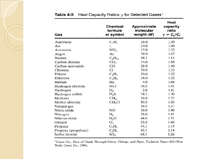
Flow of Gases or Vapors through Holes Gas Pchocked Monoatomic 1. 67 0. 478 P 0 Diatomic & air 1. 40 0. 528 P 0 Triatomic 1. 32 0. 542 P 0 The flow will be chocked: 1. P 0 > Pchocked 2. Pexternal surrounding < Pchocked For chocked discharged, C 0 = 1
Example 4. 3
Example 4. 3