
SAE Road Show II Mini Baja BRAKE SYSTEMS

SAE Road Show II Mini Baja
BRAKE SYSTEMS 101 Energy Conversion Management Presented by Paul S. Gritt
Topics To Be Presented u u u u u The Basic Concepts Hydraulic layouts Component functions Brake Balance Stopping Distance and Fade Formula SAE vs. Mini Baja Lessons Learned The Rules Questions 3
The Basic Concepts • • • Kinetic energy = heat F = ma Newton is always right! Do the calculations first When all else fails see rule 3. 4
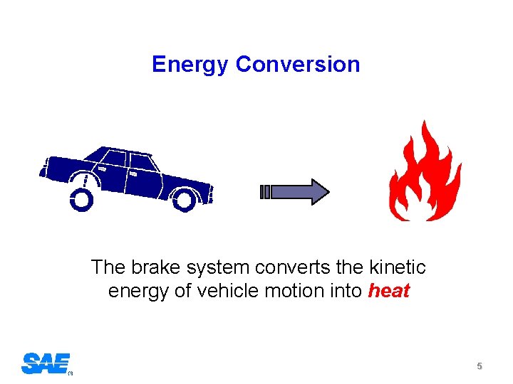
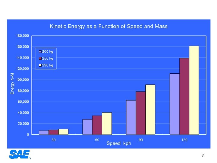
Energy Conversion The brake system converts the kinetic energy of vehicle motion into heat 5
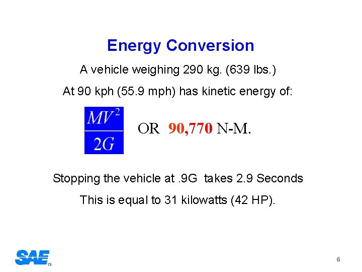
Energy Conversion A vehicle weighing 290 kg. (639 lbs. ) At 90 kph (55. 9 mph) has kinetic energy of: OR 90, 770 N-M. Stopping the vehicle at. 9 G takes 2. 9 Seconds This is equal to 31 kilowatts (42 HP). 6
7

• F = ma The Key Question! How do you calculate F? 8
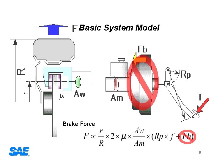
Basic System Model Brake Force 9
Hydraulic System Configurations There are two layouts of hydraulic brake systems used in cars and light trucks. Front/Rear hydraulic split: Also called axle by axle, vertical, and some times “black and white”. Diagonal Split: Also called criss-cross. The type of split is only significant in the event of a hydraulic system failure. 10
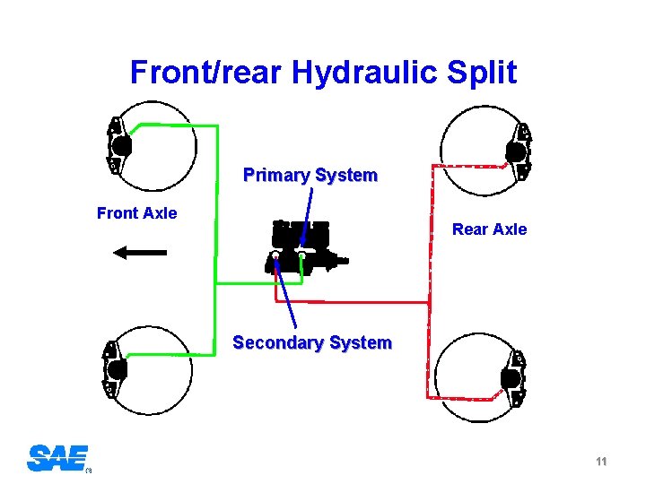
Front/rear Hydraulic Split Primary System Front Axle Rear Axle Secondary System 11
Diagonal Split System In a diagonal split system, one brake line is run to each rear brake and one to each front brake. The connections are such that the left front and the right rear brake are on one circuit and the right front and left rear are on the other circuit 12
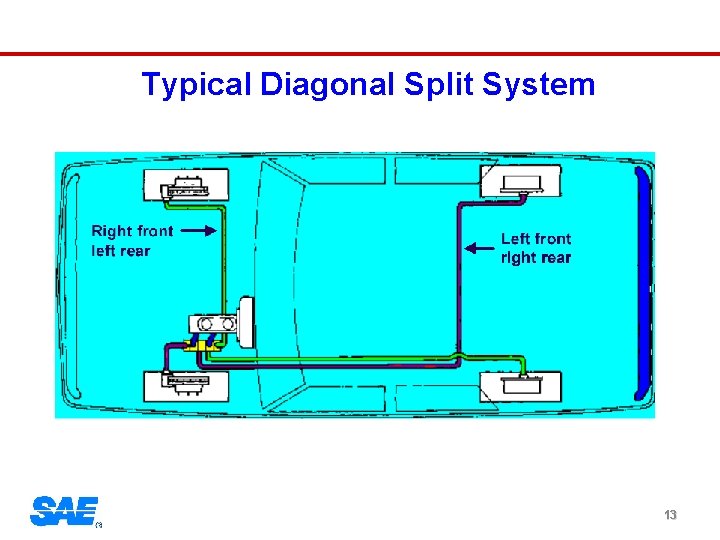
Typical Diagonal Split System 13
Brake Component Function 14
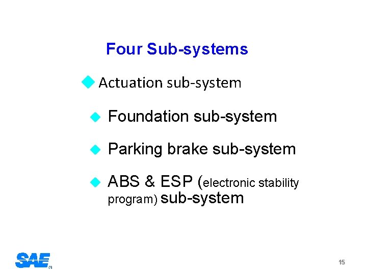
Four Sub-systems u Actuation sub-system u Foundation sub-system u Parking brake sub-system u ABS & ESP (electronic stability program) sub-system 15
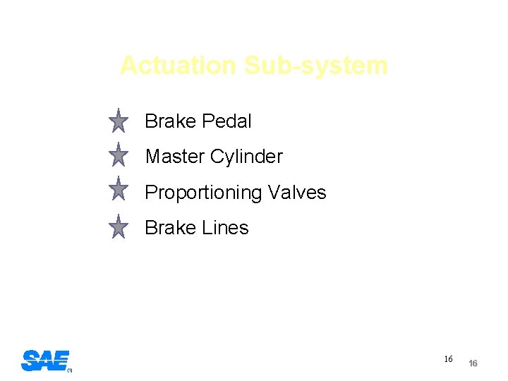
Actuation Sub-system Brake Pedal Master Cylinder Proportioning Valves Brake Lines 16 16
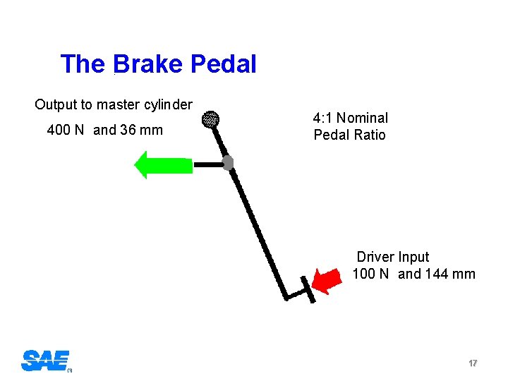
The Brake Pedal Output to master cylinder 400 N and 36 mm 4: 1 Nominal Pedal Ratio Driver Input 100 N and 144 mm 17
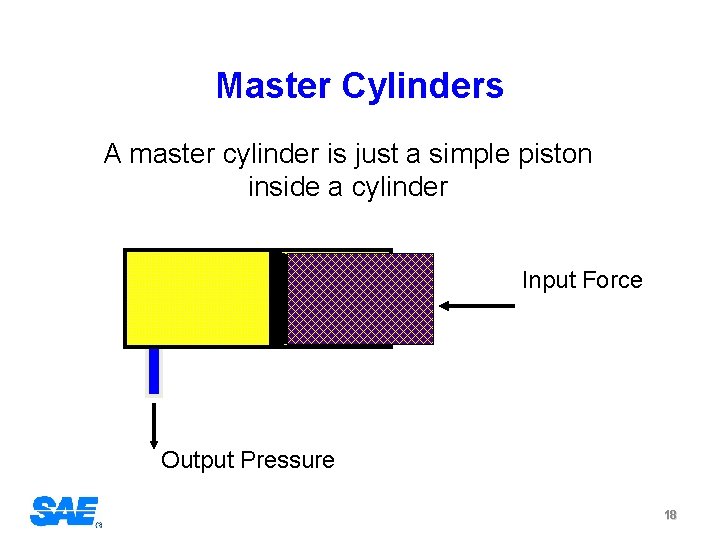
Master Cylinders A master cylinder is just a simple piston inside a cylinder Input Force Output Pressure 18
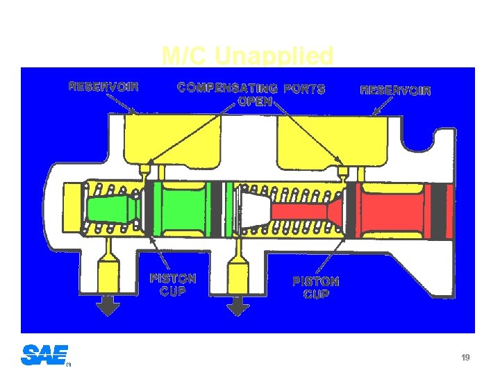
M/C Unapplied 19
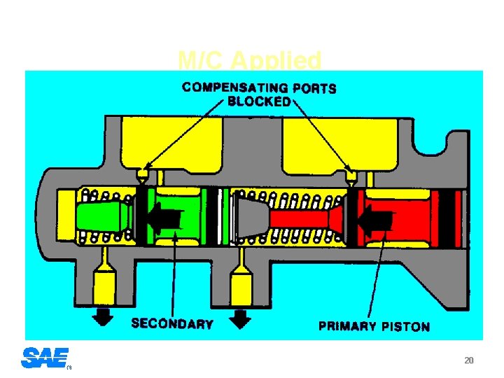
M/C Applied 20
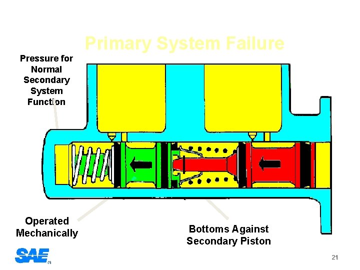
Primary System Failure Pressure for Normal Secondary System Function Operated Mechanically Bottoms Against Secondary Piston 21
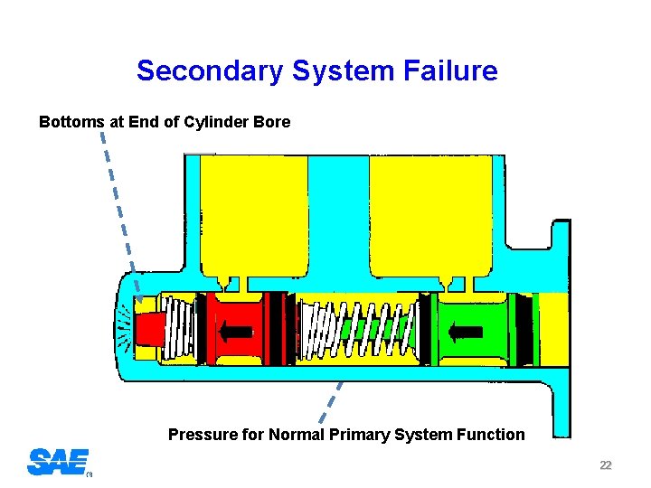
Secondary System Failure Bottoms at End of Cylinder Bore Pressure for Normal Primary System Function 22
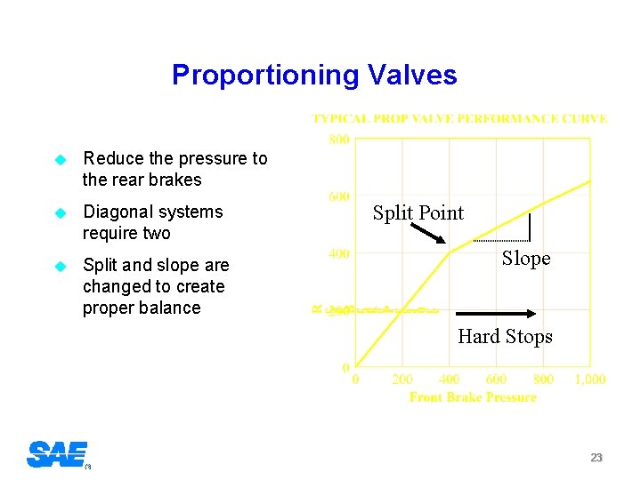
Proportioning Valves u Reduce the pressure to the rear brakes u Diagonal systems require two u Split and slope are changed to create proper balance Split Point Slope Hard Stops 23
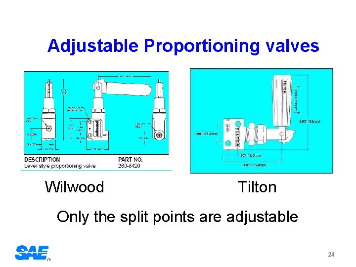
Adjustable Proportioning valves Wilwood Tilton Only the split points are adjustable 24
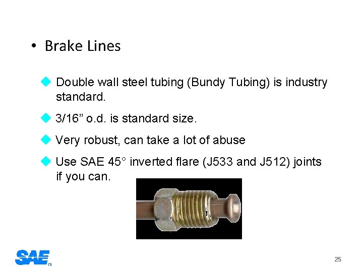
• Brake Lines u Double wall steel tubing (Bundy Tubing) is industry standard. u 3/16” o. d. is standard size. u Very robust, can take a lot of abuse u Use SAE 45° inverted flare (J 533 and J 512) joints if you can. 25
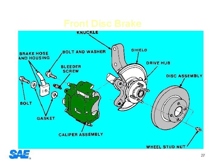
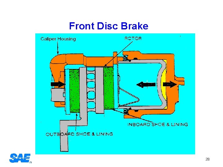
Foundation Brake Sub-system u Disc Brakes u Linings 26
Front Disc Brake 27
Front Disc Brake 28
Brake Linings • Brake linings are probably the most mis-understood part of a brake system. • The output of any brake is directly related to the coefficient of friction (µ) between the lining and the disc or drum. • The challenge is knowing what the instantaneous value of µ is during any given stop. • Any design calculations you do, go right out the window if the lining you use does not have the µ value you assumed. 29
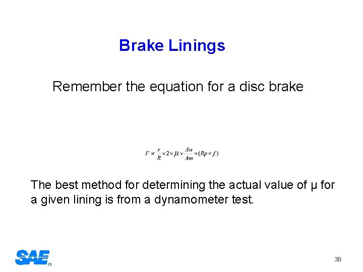
Brake Linings Remember the equation for a disc brake The best method for determining the actual value of µ for a given lining is from a dynamometer test. 30
Brake Balance 31
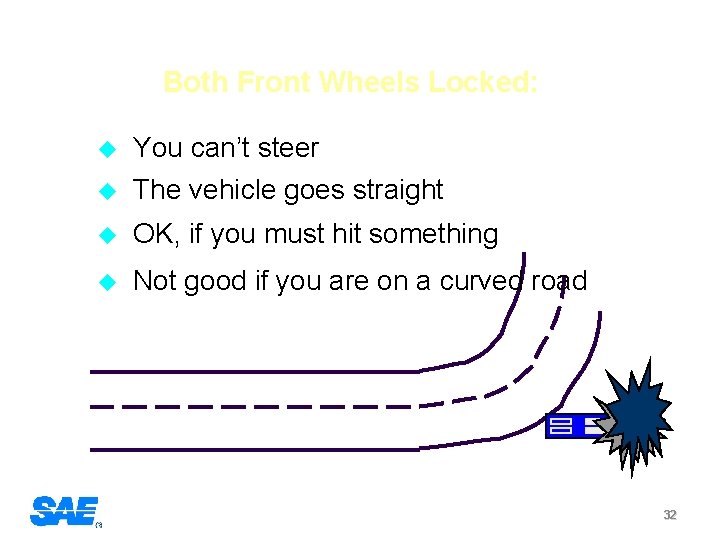
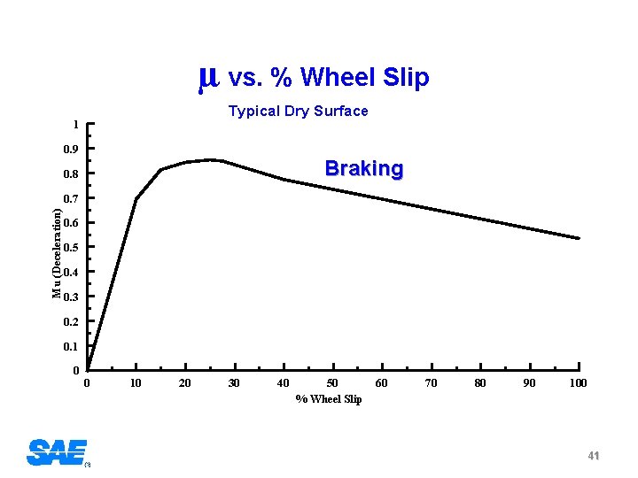
Both Front Wheels Locked: u You can’t steer The vehicle goes straight u OK, if you must hit something u Not good if you are on a curved road u 32
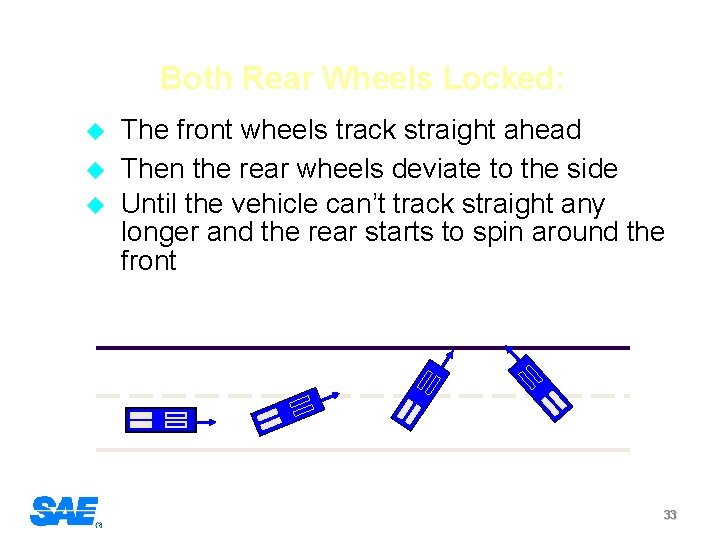
Both Rear Wheels Locked: u u u The front wheels track straight ahead Then the rear wheels deviate to the side Until the vehicle can’t track straight any longer and the rear starts to spin around the front 33
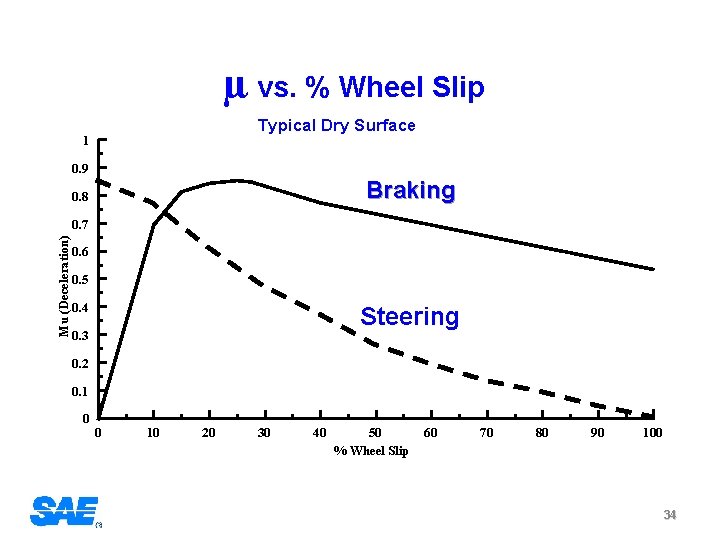
µ vs. % Wheel Slip Typical Dry Surface 1 0. 9 Braking 0. 8 Mu (Deceleration) 0. 7 0. 6 0. 5 0. 4 Steering 0. 3 0. 2 0. 1 0 0 10 20 30 40 50 % Wheel Slip 60 70 80 90 100 34
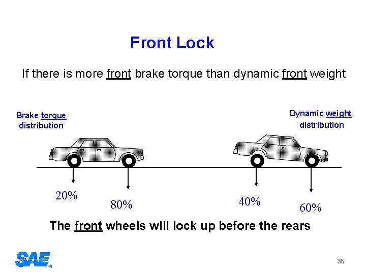
Front Lock If there is more front brake torque than dynamic front weight Dynamic weight distribution Brake torque distribution 20% 80% 40% 60% The front wheels will lock up before the rears 35
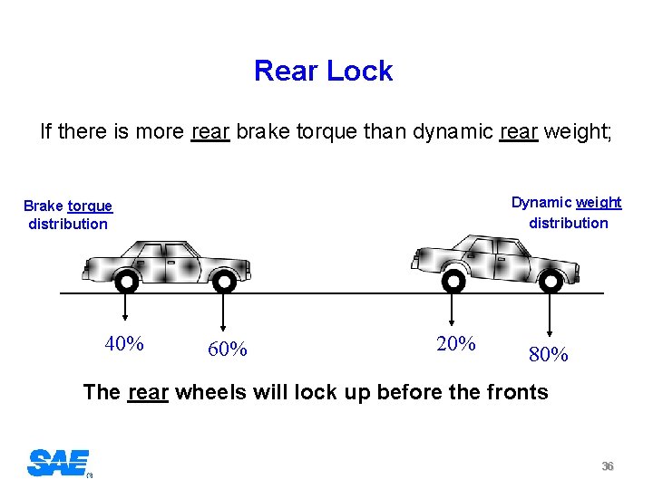
Rear Lock If there is more rear brake torque than dynamic rear weight; Dynamic weight distribution Brake torque distribution 40% 60% 20% 80% The rear wheels will lock up before the fronts 36
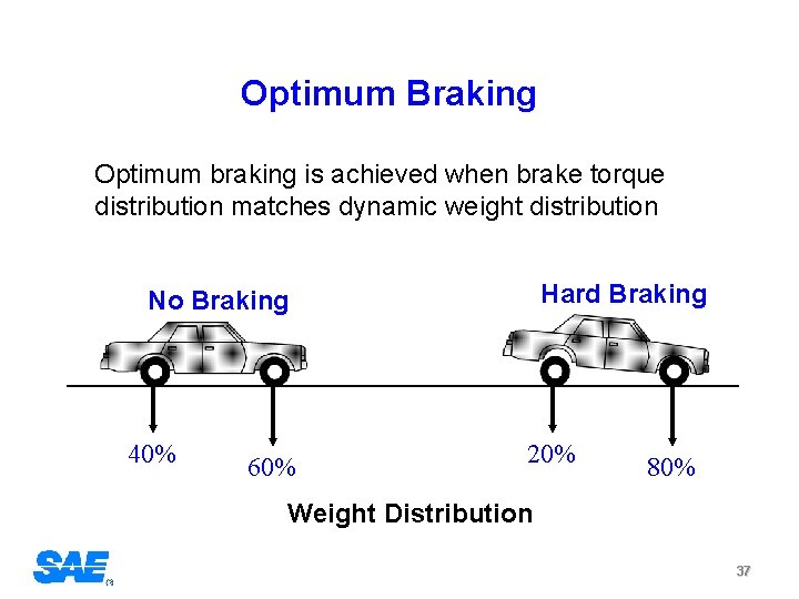
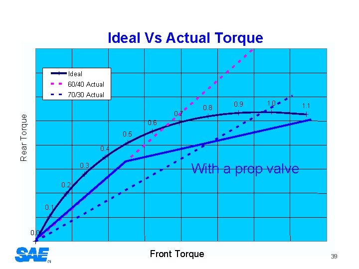
Optimum Braking Optimum braking is achieved when brake torque distribution matches dynamic weight distribution Hard Braking No Braking 40% 60% 20% 80% Weight Distribution 37
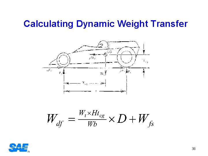
Calculating Dynamic Weight Transfer 38
Ideal Vs Actual Torque Ideal 60/40 Actual 70/30 Actual Rear Torque 0. 7 0. 8 0. 9 1. 0 1. 1 0. 6 0. 5 0. 4 0. 3 With a prop valve 0. 2 0. 1 0. 0 Front Torque 39
Stopping Distance Does not Depend on: Does Depend on: • Type of brakes • Tire to road friction • Size of brakes • Vehicle balance • Skill of driver • System Reaction Time 40
µ vs. % Wheel Slip Typical Dry Surface 1 0. 9 Braking 0. 8 Mu (Deceleration) 0. 7 0. 6 0. 5 0. 4 0. 3 0. 2 0. 1 0 0 10 20 30 40 50 % Wheel Slip 60 70 80 90 100 41
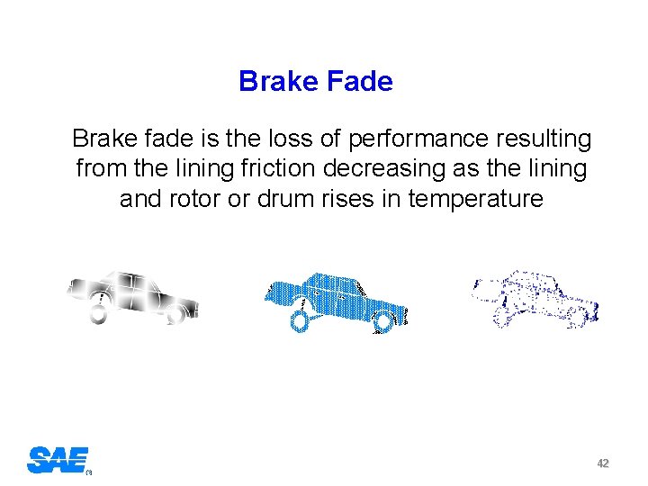
Brake Fade Brake fade is the loss of performance resulting from the lining friction decreasing as the lining and rotor or drum rises in temperature 42
The brake system design must match the vehicle objectives Formula SAE vs. Mini Baja 43
Formula SAE u u Absolute reliability High Speeds Maximum possible decel without locking Consistent balance with changing temperatures Mini Baja u u Absolute reliability Low Speeds Very hostile environment Brake must work when wet and muddy 44
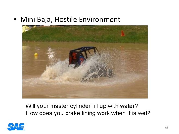
• Mini Baja, Hostile Environment Will your master cylinder fill up with water? How does you brake lining work when it is wet? 45

Lessons Learned 46
Don’t Do Something Because: u u u The other guys do it. All the race cars have it. It looks really cool 47

Design to a Specific Objective: u u u Do the math first Verify your assumptions Take the easy solution (KISS) 48
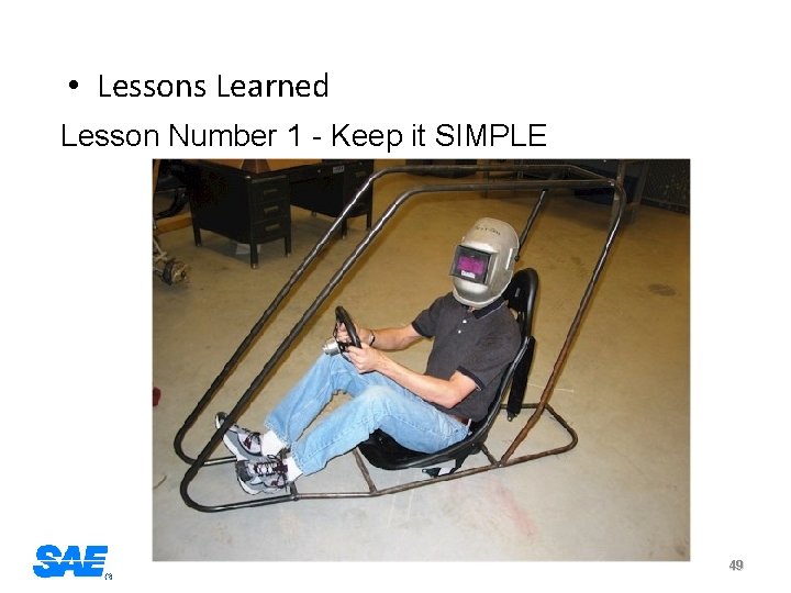
• Lessons Learned Lesson Number 1 - Keep it SIMPLE 49
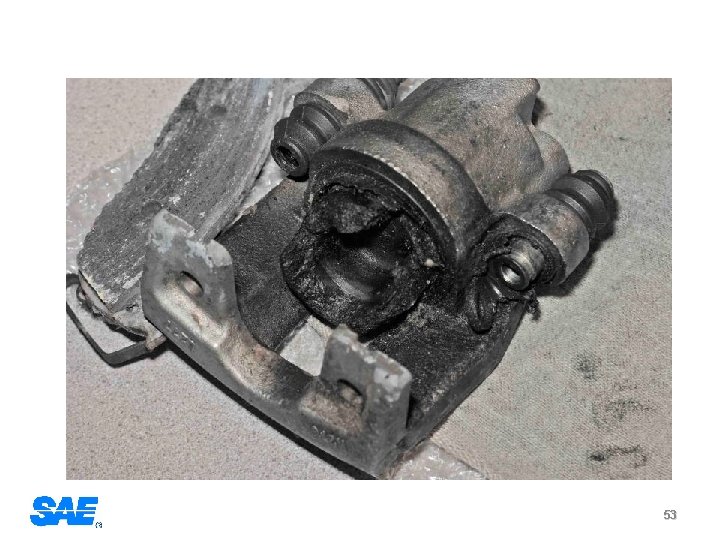
• Lessons Learned Lesson Number 2 - Keep it light; but not too light. • 90% of the braking energy goes into the rotor • If the rotor is too light it gets very hot • If the temperatures get too high very nasty things can happen. 50
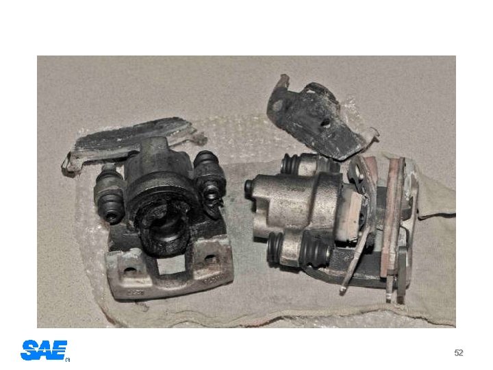
• • Too 2006 light DCAE program involved a Hemi powered Grand Cherokee. • One team used much smaller rear brakes and rotors to save a few pounds on a 3200 lb vehicle with 500 hp. • The vehicle went off the end of the main straight at over 100 mph on the third lap because of brake failure. 51
52
53
• Lessons Learned Lesson Number 3 - Packaging and Integration drive 90% of design Lesson Number 4 - Read the rules Lesson Number 5 - Allow enough time for details and testing 54
• Brake rules - The car must have four wheel brakes operated by a single control. - It must have two independent hydraulic circuits with independent fluid reserves. - The brake system must be capable of locking all four (4) wheels, and stopping the vehicle in a straight line The braking systems must be protected with scatter shields from failure of the drive train (FSAE only) - A brake pedal over-travel switch must be installed. This switch must kill the ignition and cut the power to any electrical fuel pumps. (FSAE only) - The car must be equipped with a red brake light that illuminates when ever the brakes are applied 55

Any Questions 56
- Slides: 56