RUTHERFORD COUNTY CODES OFFICIAL ASSOCIATION PRESENTS SIGNIFICANT CHANGES


 Crawl spaces not intended to be used for storage")


 A handrail can project up")


 shall not be considered a")


 and chlorinated polyvinyl chloride (CPVC)")


- Slides: 102
RUTHERFORD COUNTY CODES OFFICIAL ASSOCIATION PRESENTS SIGNIFICANT CHANGES TO THE 2018 INTERNATIONAL RESIDENTIAL CODE
WHAT TO EXPECT § These class will cover the changes in the 2015 and 2018 IRC. § We will discuss most of the significant changes. What is significant to you may not be significant to others, we did our best select what most would think are significant changes. § Due to time constraints we will not be able to cover all the changes or significant changes. § The new codes will take effect for Permits issued February 1 st. Except La. Vergne
Administration
The 2018 IRC applies to buildings which are: >Single Family and Two Family Dwellings that are 3 stories or less. > Townhomes that are 3 stories or less. > Most uses in the above structures that have a limited occupant load. Bed and Breakfasts, Daycares, Group Homes, and similar uses. State law exempts single family dwellings, duplexes or townhomes from being sprinkled unless required by the local jurisdiction. -occupied lodging houses, 5 or fewer 1. Care facility in dwelling unit, 5 or fewer (custodial) 2. Care facility in dwelling unit, 5 or fewer (medical) 3. Care facility in single-family, 5 or fewer (care) Administration
Building Planning
Wind Speed § The design wind speed has been increased to 115 mph.
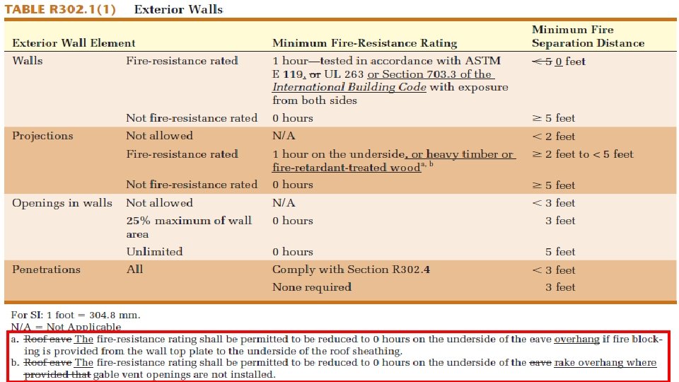
ROOF OVERHANGS Roof overhangs within 5’-0” to 2’ 0” from the property line must have: 1) The underside of the soffit one hour rated or; 2) Fire blocking is installed from the top of the wall to the underside of the roof deck.
GABLE ENDS The fire protection of the rake at the gable end of the house is not required where a gable vent is not installed.
Building Planning
FLOOR ASSEMBLIES Floor assemblies that are not required elsewhere in the code to be fire-resistance rated, shall be provided with ½-inch gypsum… on the underside of wood I’s or Open Web Trusses used as floor framing members. Modified in the 2018 code, is the addition of electric-powered heating appliances in addition to fuel-fired ones.
EXCEPTIONS § Exceptions: § 1) Crawl spaces not intended to be used for storage or installation of heating equipment. § 2) Rooms or spaces 80 sf or less and separated with ½” sheetrock or 5/8” wood structural panels with fire blocking installed between floor joists. § Wood I’s treated to comply with this section. § LP® Flame. Block® I-Joist Advantages is one of many that comply.
GLAZING REQUIREMENTS § 1. Where the glazing is within 24 inches of either side of the door in the plane of the door in a closed position. § 2. Where the glazing is on a wall perpendicular to less than 180 degrees from the plane of the door in a closed position and within 24 inches of the hinge side of an inswinging side of a door. § Exceptions: § 1. Decorative glazing. § 2. Where there is an intervening wall or other permanent barrier between the door and the glazing. § 3. Where access through the door is to a closet or storage area 3 feet or less in depth. Glazing in this application shall comply with Section R 308. 4. 3. § 4. Glazing that is adjacent to the fixed panel of patio door.
GLAZING AT DOORS
SAFETY GLAZING AT DOORS Window is in a wall that is with 180 degrees of the plane of the door in the closed position. One window on side of door in swing the other is not. Required by the 2018 Not required by 2018
GLAZING AT DOORS
GLAZING AT WET LOCATIONS § Glazing in walls, enclosures, or fences containing or facing hot tubs, spas, whirlpools, saunas, steam rooms, bathtubs, showers, and indoor or outdoor swimming pools where the bottom exposed edge of the glazing is less than 60 inches measured vertically above any standing or walking surface shall be considered to be a hazardous location. This shall apply to single glazing and all panes in multiple glazing. § Exception: Glazing that is more than 60 inches, measured horizontally and in a straight line, from the water’s edge of a bathtub, hot tub, spa, whirlpool, or swimming pool or from the edge of a shower, sauna, or steam room.
SAFETY GLAZING AT SHOWERS, HOT TUBS AND SAUNAS
GLAZING AT STAIR LANDING Only glazing within 36” above the landing and in front of or in plane of the bottom tread must be safety glazing. A guard 18” from the glazing can be installed in lieu of the safety glazing.
GLAZING IN HANDRAILS § R 308. 4. 4 GLAZING IN GUARDS AND RAILINGS. Glazing in guards and railings, including structural baluster panels and nonstructural in-fill panels, regardless of area or height above a walking surface shall be considered to be a hazardous location. § R 308. 4. 4. 1 STRUCTURAL GLASS BALUSTER PANELS. Guards with structural glass baluster panels shall be installed with an attached top rail or handrail. The top rail or handrail shall be supported by not less than three glass baluster panels, or shall be otherwise supported to remain in place should one glass baluster panel fail. § Exception: An attached top rail or handrail is not required where the glass baluster panels are laminated glass with two or more glass plies of equal thickness and of the same glass type.
HANDRAIL AT TOP
EMERGENCY ESCAPE AND RESCUE OPENINGS § This section was completely rewritten in the 2015 IRC, however no technical changes were made. The section was rewritten to clarify: § 1) Emergency escape and rescue openings are required in all sleeping rooms, habitable attics and basements. Basements used for mechanical equipment or storm shelters under 200 sf are exempt. § 2) If a door is used in lieu of a window it must meet the egress door requirements and can be a sliding type door. § If a dwelling is sprinkled a basement can have two egress doors or one emergency escape and rescue window and one egress door. § Specifies area well requirements for emergency escape and rescue openings. Permanent ladders and steps are allowed. § New sections clarify when rescue openings are required in additions and alteration of basements.
EMERGENCY ESCAPE AND RESCUE WINDOW SIZES NO CHANGES
DWELLINGS WITH SPRINKLER SYSTEMS BASEMENT RESCUE OPENINGS
STAIRWAY CHANGES § Changes to stairways include: § 1) A handrail can project up to 6 ½” into the stairway width at an adjacent stair tread, nosing or landing. Must maintain required clearances. § 2) Ships ladders and alternating tread devices are allowed to serve as a means of egress for a loft that is 200 sf or less. A new section specifies tread, riser and handrail requirements of these devices. § 3) The maximum rise of a stairway without an intermediate landing as been increased from 12’-0” to 12’_7”. § Nosing are required on all landings, floors and treads. If tread depth is 11” or greater, a nosing is not required. This change is to promote a more consistent step pattern on stairways. § Open risers are permitted on spiral stairs and stairs that are not more than 30” above grade. § Guard height are no longer measured from the seat of fixed seating. Guard height is measured from the walking surface.
A 6 ½” projection is allowed as long as the required width of 32 ½” for a handrail on one side and 27” on two sides is maintained. The 1 ½ clearance behind the handrail must also be maintained. Building Planning
HANDRAIL PROJECTIONS
Nosing required at landings Building Planning
SMOKE DETECTORS § Smoke detector section has been reworked to include the following: § 1) Ionization smoke detectors must be 20 feet from cooking appliances or 10 feet if equipped with an alarm silencing switch. § 2) Photoelectric must be 6 feet from cooking appliances § 3) Smoke detectors cannot be installed within 3 feet of a door to a bathroom that has a tub or shower. § If either of the above locations result in a smoke detector not being installed, the above requirements shall be waived. § If a home owner has a fire alarm system installed; it does not have to be monitored by a central station, however it must preform the same as interconnected smoke detectors and must be owned the home owner. § In alterations, smoke detectors must be interconnected regardless if wall or ceiling finishes are removed.
SMOKE DETECTOR LOCATIONS Ionization detectors must be 20 feet from permanent cooking equipment. Photoelectric detectors must be installed at least 6 feet from permanent cooking equipment. All smoke detectors must be installed at least 3 feet from a door that serves a bathroom with a tub or shower.
CARBON MONOXIDE DETECTORS § This section has been reworked to mimic smoke detector requirements: § 1) Required in dwelling units that have either an attached garage with an opening into the dwelling unit; or fuel fired appliance in the dwelling unit. § 2) Required outside each sleeping room or sleeping room group and in each sleeping room that has a fuel fired appliance or a fuel fired appliance in the sleeping rooms attached bathroom. § 3) Carbon monoxide detectors shall be connected to a permanent power supply with battery back-up and where multiple detectors are required they shall be interconnected. § 4) Alterations; that are interior and require a permit to a dwelling unit that has conditions as listed in item 1 above shall have carbon monoxide detectors installed as in new construction. Battery operated is permitted and interconnection is not required. § 5) Combination smoke and carbon monoxide detectors are permitted where listed with UL for such use.
MEZZANINES
MEZZANINES § Mezzanines that comply with the following will not be counted as a story: § 1) Shall have a clear ceiling height above and below of 7’-0” minimum. § 2) Have a means of egress that complies with the IRC. § 3) Shall not be more than 1/3 of the area which it is in. Mezzanines in dwelling units that are sprinkled can be ½ the area of the room it is in if the only enclosed spaces are closets and bathrooms and the mezzanine is not above the 2 nd floor. § 4) Shall be open to the room it is in except for walls or guards no more than 42” tall; except that rooms no more than 10% or the mezzanine floor area. § 5) Mezzanines can be fully enclosed if it is not more than 2 stories above grade, has 2 means of egress and is sprinkled.
HABITABLE ATTICS
HABITABLE ATTICS § A habitable attic (finished or unfinished) shall not be considered a story when complying with all of the following requirements: § 1. The occupiable floor area is not less than 70 square feet. § 2. The occupiable floor area has a ceiling height as required for habitable spaces. § 3. The occupiable space is enclosed by the roof assembly above, knee walls (if applicable) on the sides and the floor-ceiling assembly below. § 4. The floor of the occupiable space shall not extend beyond the exterior walls of the floor below.
m u m i in M g n i t o fo Building Planning e z i s
R 507. 3. 1 The minimum size of concrete footings shall be in accordance with Table R 507. 3. 1, based on the tributary area and allowable soil-bearing pressure in accordance with table R 401. 4. 1. Building Planning
Building Planning
Building Planning
R 507. 4 For single level wood-framed decks with beams sized in accordance with Table R 507. 5, deck post size shall be in accordance with Table R 507. 4. Building Planning
Building Planning
R 507. 4 For single level wood-framed decks with beams sized in accordance with Table R 507. 5, deck joist size shall be in accordance with Table R 507. 6. Building Planning
Building Planning
DECK CONSTRUCTION
R 507. 5 Maximum allowable spans for wood deck beams… shall be in accordance with Table R 507. 5 Building Planning
Building Planning
MINIMUM BUILDING FOOTING SIZES § Some got bigger and some got smaller. § Footing sizes are now in three different tables: § 1. One, two, and three stories conventional Light Frame Construction, § 2. One, two, and three stories with 4” brick over light frame construction, and § 3. One, two, and three stories built with 8” concrete block. § These tables do not take into consideration the different roof loads such as up north where snow loads are much higher. The 2018 IRC provides tables that are now including the roof loads.
FOUNDATION ANCHOR BOLTS § Foundation Anchor Bolts shall be: § ½” diameter; extend minimum 7” into concrete or grouted cell. § Spaced minimum 6’-0” on center. § Minimum 2 bolts per plate. § Shall be located in middle third of sill or bottom plate.
SOUTHERN YELLOW PINE FLOOR AND CEILING JOIST AND GIRDER SPANS § Girder and joist spans have been updated: § To match the American Lumber Standards Committee (ALSC) new design values as published in Southern Pine Inspection Bureau Supplement No. 13 to the 2002 Standard Grading Rules for Southern Pine Lumber. § Chances are lumber suppliers have been using these new spans for several years now. § Girder and header span tables were changed, spans have been shortened several inches. § Footnotes have been added to girder and header tables requiring lateral bracing of headers 2 X 8 and larger or the allowable span shall be multiplied by 0. 7. § Example a 10’-1” span becomes a 7’-1” span if not laterally supported.
GIRDER BRACING
KING STUDS AT HEADERS
RETAINING WALLS § Retaining walls that are not laterally supported at the top and that retain in excess of 48 inches of unbalanced fill, or retaining walls exceeding 24 inches in height that resist lateral loads in addition to soil, shall be designed in accordance with accepted engineering practice to ensure stability against overturning, sliding, excessive foundation pressure, and water uplift. Retaining walls shall be designed for a safety factor of 1. 5 against lateral sliding and overturning. This section shall not apply to foundation walls supporting buildings.
UNVENTED CRAWL SPACE § Unvented Crawl Spaces must have a dehumidifier capable of extracting 70 pints per day for ever 1, 000 sf of crawl space. § This is in addition to the supply and return vent that is extended into the crawl space.
WATER RESISTIVE BARRIERS § This section has been re-written to clarify how WRB’s should be installed. § 1) 15 # asphalt shall be installed horizontally. The upper layer shall lap over the lower layer with a 2” lap. End joints shall be lapped 6”. § 2) Other approve WRB’s shall be installed in accordance with the manufacturer’s installation instructions. § Vinyl siding must have a WRB installed behind it. § All accessory structures must have a water resistive barrier installed behind the exterior finish material.
EFIS SYSTEMS § EFIS without drainage backing installed on concrete block or concrete only. § EFIS with drainage backing installed on all other backing. § Drainage must provide 90% efficiency. § All EFIS must stop minimum 6” above grade. § EFIS must have a WRB. § Decorative trim cannot be faced nailed through EFIS.
VINYL SIDING Vinyl Siding must be attached at 16” oc for horizontal siding. 12” oc vertical siding Nails must penetrate framing member; unless test data allows fasteners into sheathing only.
VINYL AND WOOD PANEL SOFFITS Wood panel soffits shall be minimum 3/8” thick and fastened at 6” oc along the edge and 12” oc in the intermediate supports. Vinyl soffit panels shall be attached so that no unsupported span shall exceed 16”.
FACTORY BUILT CHIMNEY INSULATION SHIELD Where factory-built chimneys pass through insulated assemblies, an insulation shield constructed 0. 0187 inch (26 gage) steel and be installed to provide clearance between the chimney and the insulation material; but not be less than the clearance to combustibles specified by the chimney manufacturer’s installation instructions. Where chimneys pass through attic space, the shield shall terminate not less than 2 inches above the insulation materials and shall be secured in place to prevent displacement. Insulation shields provided as part of a listed chimney system shall be installed in accordance with the manufacturer’s installation instructions.
ENERGY CERTIFICATE Energy certificates must be installed on the interior of the dwelling, preferably on the wall in the furnace room. It can be installed on the electric panel if it is on the interior of the building and not cover-up any NEC required labels. Energy Conservation
ATTIC AND ACCESS DOORS Access Hatches and Doors from conditioned to unconditioned spaces must be weather-stripped and insulated to the same R value as the surrounding walls. The access door construction must be such that the insulation will stay in place and the R value will not be reduced. A door that has a listed fenestration rating as required for other openings must also be used.
Energy Conservation
FLOOR INSULATION § Floor framing cavity insulation shall be installed to maintain permanent contact with the underside of the subfloor decking. § Exception: The floor framing cavity insulation shall be permitted to be in contact with the topside of sheathing or continuous insulation installed on the bottom side of floor framing where combined with insulation that meets or exceeds the minimum wood frame wall R-value and that extends from the bottom to the top of all perimeter floor framing members.
FLOOR INSULATION
INSULATION AT CORNERS AND HEADERS Insulation is required IF voids are present
ATTIC INSULATION REDUCTION § Ceilings without attic spaces. § Where insulation R-values greater than R-30 in the ceiling are required and the design of the roof/ceiling assembly does not allow sufficient space for the required insulation, the minimum required insulation Rvalue for such roof/ceiling assemblies shall be R-30. Insulation shall extend over the top of the wall plate to the outer edge of such plate and shall not be compressed. This reduction of insulation from the requirements shall be limited to 500 square feet or 20 percent of the total insulated ceiling area, whichever is less.
DUCTS IN ATTICS § Where supply and return air ducts are partially or completely buried in ceiling insulation, such ducts shall comply with all of the following: § 1. The supply and return ducts shall have an Rvalue not less than R-8. § 2. At all points along each duct, the sum of the ceiling insulation R-values above the top of the duct, and against and below the bottom of the duct shall be not less than R-19, excluding the duct R-value. § Exception: Sections of supply ducts less than 3 feet from the supply outlet shall not be required to comply with these requirements.
Mechanical
KITCHEN EXHAUST AND MAKE-UP AIR Kitchen exhaust hoods that exhaust more than 400 cfm, shall have a natural or mechanical make-up air system. Dampers shall automatically open when the exhaust hood is activated.
KITCHEN EXHAUST AND MAKE-UP AIR Inlet from the make-up air can be in another room as long as there is a permanent opening between the kitchen and the room where the outside air damper is located.
KITCHEN COOKING EQUIPMENT § Overhead and downdraft exhaust systems must be listed for such use. § Open top broiler units must have an overhead exhaust hood or downdraft hood. § Kitchen exhaust systems must discharge to the exterior unless listed for recirculating exhaust air. § Ducts for domestic kitchen cooking appliances equipped with down-draft exhaust systems shall be permitted to be constructed of schedule 40 PVC pipe and fittings provided that the installation complies with all of the following: § 1. The duct is installed under a concrete slab poured on grade. § 2. The underfloor trench in which the duct is installed is completely backfilled with sand or gravel. § 3. The PVC duct extends not more than 1 inch above the indoor concrete floor surface. § 4. The PVC duct extends not more than 1 inch above grade outside of the building. § 5. The PVC ducts are solvent cemented.
DRYER EXHAUST DUCTS The passageway of dryer exhaust duct terminals shall be undiminished in size and shall provide an open area of not less than 12. 5 square inches Mechanical
DRYER EXHAUST DUCTS Length Identification. Where the exhaust duct equivalent length exceeds 35 feet, the equivalent length of the exhaust duct shall be identified on a permanent label or tag. The label or tag shall be located within 6 feet of the exhaust duct connection. Dryer ducts installed in wall cavities shall be provided with sufficient space that the wall cavity does not compress or change the natural shape of the duct. Mechanical
Mechanical
MAXIMUM EXHAUST DUCT LENGTH § Exhaust duct length shall determined by the following chart.
MAXIMUM EXHAUST DUCT LENGTH § Duct length that exceeds the chart can be approved if verified using an air flow test using a flow hood or flow grid or other approved equipment.
DUCT JOINT SEALING Joints, Seams and Connections. Snap-lock and button -lock have previously been exempt from the requirement of tapes and mastics, no more, however. Mechanical
Snap Lock Duct Mechanical
RETURN AIR OPENINGS § 1. Openings shall not be located less than 10 feet measured in any direction from an open combustion chamber or draft hood located in the same room § 2. The amount of return air taken from any room or space shall be not greater than the flow rate of supply air delivered to such room or space. § 3. Return shall be sized in accordance with the appliance or equipment manufacturers’ installation instructions, Manual D or the design of the registered design professional. § 4. Return air shall not be taken from a closet, bathroom, toilet room, kitchen, garage, mechanical room, boiler room, furnace room or unconditioned attic. § Exceptions: § 1. Return air from a kitchen is not prohibited where such return air openings serve the kitchen only, and are located not less than 10 feet from the cooking appliances. § 3. Taking return air from an unconditioned crawl space shall not be accomplished through a direct connection to the return side of a forced-air furnace. Transfer openings in the crawl space enclosure shall not be prohibited.
CONDENSATE PUMPS § Condensate pumps located in uninhabitable spaces, such as attics and crawl spaces, shall be connected to the appliance or equipment served such that when the pump fails, the appliance or equipment will be prevented from operating. Pumps shall be installed in accordance with the manufacturer’s instructions.
Fuel Gas
CSST BONDING
PROTECTION OF CONCEALED PIPING AGAINST PHYSICAL DAMAGE § Notches or Bored Holes: Gas piping in bored holes or notches and the piping is within 1 ½” of the face to which sheetrock will be attached, the entire width of the stud plus 4” beyond each side of the stud shall be protected with a plate. § Piping Installed in Other Locations. Where the piping is located within a framing member and is less than 1 ½” inches from the framing member face to which wall, ceiling or floor membranes will be attached, the piping shall be protected by shield plates that cover the width and length of the piping. Where the piping is located outside of a framing member and is located less than 1 ½” inches from the nearest edge of the face of the framing member to which the membrane will be attached, the piping shall be protected by shield plates that cover the width and length of the piping
Gas Piping
VENT TERMINATION LOCATION § Appliance and equipment vent terminals shall be located such that doors cannot swing within 12 inches horizontally of the vent terminal. Door stops or closers shall not be installed to obtain this clearance.
MISCELLANEOUS FUEL GAS CHANGES Plastic Pipe. Polyvinyl chloride (PVC) and chlorinated polyvinyl chloride (CPVC) plastic pipe, tubing and fittings shall not be used to supply fuel gas. Fuel shut off valves attached to tubing shall be rigidly secured independent from the tubing. Shutoff valves serving movable appliances, such as cooking appliances and clothes dryers, shall be considered to be provided with access where installed behind such appliances. Fuel Gas
COMMERCIAL COOKING EQUIPMENT § Commercial cooking equipment is permitted in a dwelling when the installation is designed by a licensed professional or the cooking equipment is listed for commercial and domestic uses.
Plumbing
M 2503. 5 DWV Systems Testing. This section describes that the head pressure for a water test on drain, waste, and vent systems (Interior Plumbing Only) has been reduced from 10 feet to 5 feet. Plumbing
M 2603. 2. 1 Protection Against Physical Damage. Steel shield plates are required where piping is within 1 1/4” instead of 1 1/2”. Plumbing
Sink and Dishwasher. The dishwasher discharge pipe or tubing shall rise to the underside of the counter and be secured to remain in place. Plumbing
PRESSURE RELIEF PIPING § The discharge piping serving a pressure relief valve, temperature relief valve or combination valve shall: § Terminate not more than 6 inches and not less than two times the discharge pipe diameter above the floor or waste receptor flood level rim. § Be one nominal size larger than the size of the relief valve outlet, where the relief valve discharge piping is constructed of PEX or PE-RT tubing. The outlet end of such tubing shall be fastened in place.
TRAP SEALS § Trap seals for emergency floor drains or floor drains subject to evaporation shall be protected by: § 1) Potable water trap primer. § 2) Reclaimed or gray water trap primer. § 3) Waste water trap primer § 4) Barrier Type Trap Seal Protective Device
SWAY BRACING § Where horizontal pipes 4 inches and larger convey drainage or waste, and where a pipe fitting changes in the flow direction greater than 45 degrees for, rigid bracing or other rigid support arrangements shall be installed to resist movement of the upstream pipe sizes 4 inches and larger. In the direction of flow. A change of flow direction into a vertical pipe shall not require the upstream pipe to be braced.
WATER HAMMER ARRESTOR § The flow velocity of the water distribution system shall be controlled to reduce the possibility of water hammer. A water hammer arrestor shall be installed where quick closing valves are utilized. Water- hammer arrestors shall be installed in accordance with the manufacturer’s instructions. Water-hammer arrestors shall conform to ASSE 1010. § Quick closing valves can be at dishwashers, clothes washer and water closets. § Installing a water hammer arrestor on the hot and cold water line in the vanity under each sink will satisfy this requirement.
AIR ADMITTANCE VALVES § Air admittance valves shall not be used to vent sumps or tanks except where the vent system for the sump or tank has been designed by an engineer. Air admittance valves shall not be installed on outdoor vent terminals for the sole purpose of reducing clearances to gravity or mechanical air intakes.
THANK YOU!