
Rudolf Wieser Matthias Baechle Valerijs Knazkins ATPE Improving
Rudolf Wieser, Matthias Baechle, Valerijs Knazkins – ATPE Improving Power System Stability Through Integrated Power System Stabilizers © ABB Group 23 November 2020 | Slide 1
OUTLINE Controlled Generator on Grid § The main functions of an Automatic Voltage Regulator (AVR) § The main functions of a Power System Stabilizer (PSS) How to test an AVR system § Introduction to Real time Simulator Grid Code compliance testing § © ABB Group 23 November 2020 | Slide 2 UNITROL built in compliance test functions
The main functions of an AVR Automatic Voltage Regulator State-of-the-art excitation systems are equipped with fast acting voltage regulators: § § Advantages: § Fast acting voltage control and reactive power support § Providing synchronizing torque component Disadvantage: § § Solution to the reduced damping torque problem § © ABB Group 23 November 2020 | Slide 3 Introducing negative damping torque component Power System Stabilizers
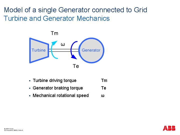
Model of a single Generator connected to Grid Turbine and Generator Mechanics © ABB Group 23 November 2020 | Slide 4 § Turbine driving torque Tm § Generator braking torque Te § Mechanical rotational speed ω
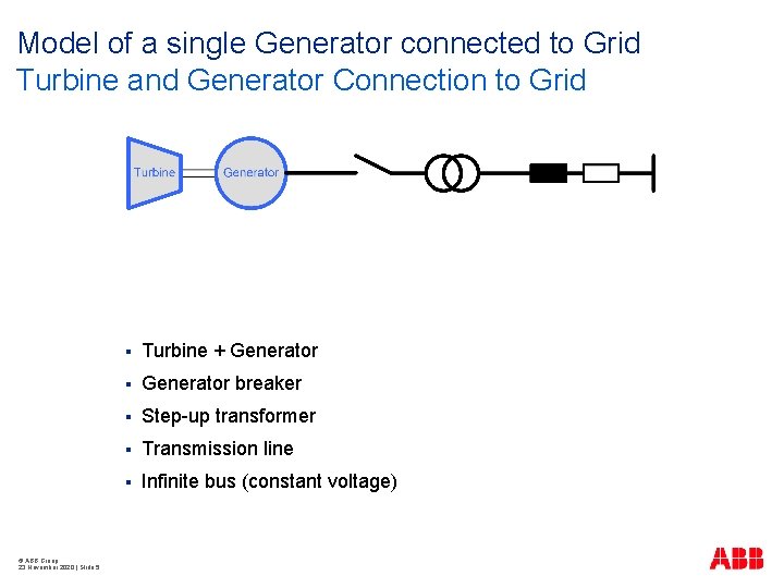
Model of a single Generator connected to Grid Turbine and Generator Connection to Grid © ABB Group 23 November 2020 | Slide 5 § Turbine + Generator § Generator breaker § Step-up transformer § Transmission line § Infinite bus (constant voltage)
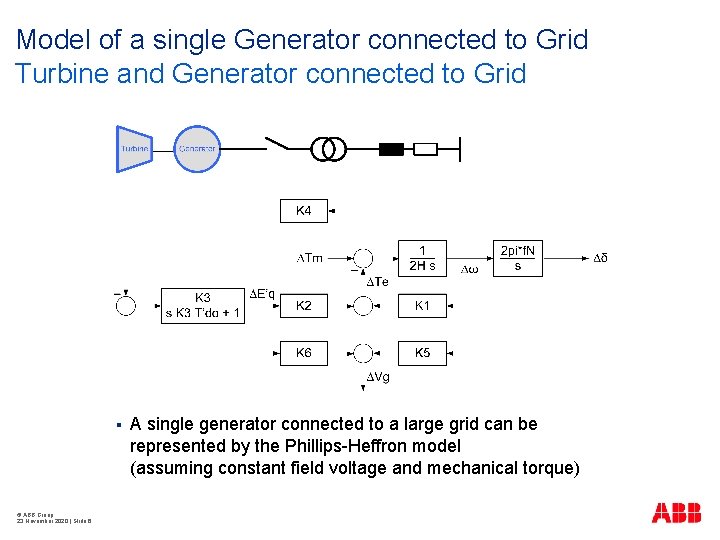
Model of a single Generator connected to Grid Turbine and Generator connected to Grid § © ABB Group 23 November 2020 | Slide 6 A single generator connected to a large grid can be represented by the Phillips-Heffron model (assuming constant field voltage and mechanical torque)
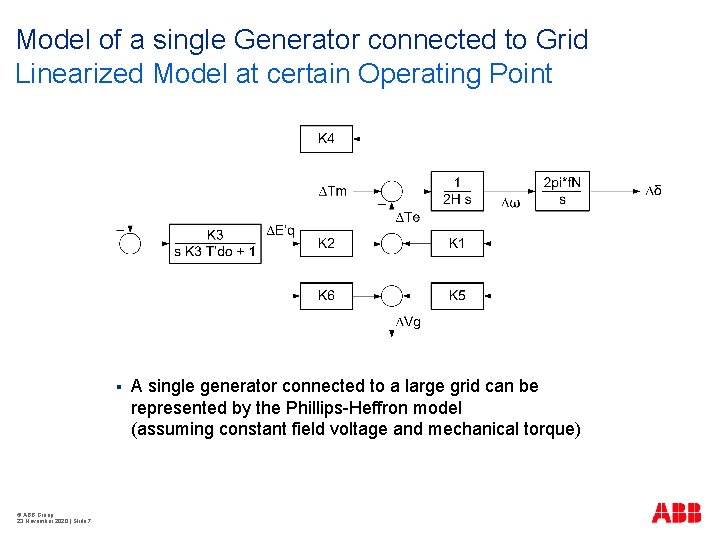
Model of a single Generator connected to Grid Linearized Model at certain Operating Point § © ABB Group 23 November 2020 | Slide 7 A single generator connected to a large grid can be represented by the Phillips-Heffron model (assuming constant field voltage and mechanical torque)
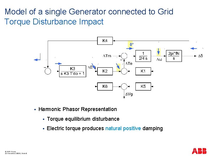
Model of a single Generator connected to Grid Torque Disturbance Impact § © ABB Group 23 November 2020 | Slide 8 Harmonic Phasor Representation § Torque equilibrium disturbance § Electric torque produces natural positive damping
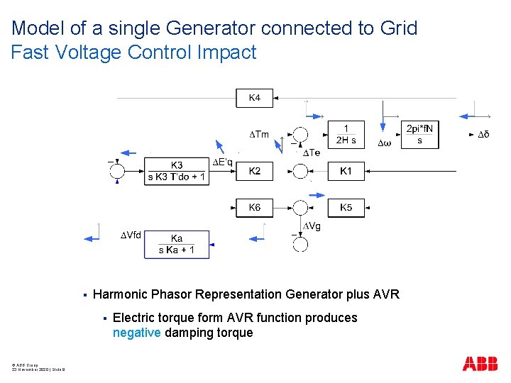
Model of a single Generator connected to Grid Fast Voltage Control Impact § Harmonic Phasor Representation Generator plus AVR § © ABB Group 23 November 2020 | Slide 9 Electric torque form AVR function produces negative damping torque
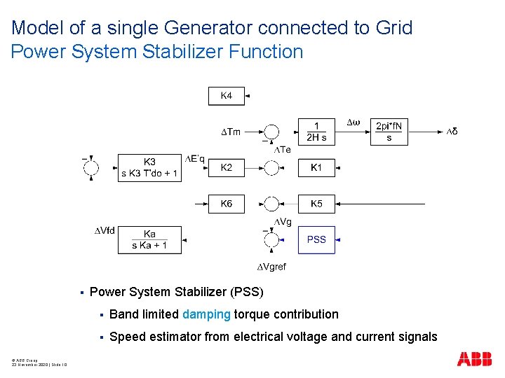
Model of a single Generator connected to Grid Power System Stabilizer Function § © ABB Group 23 November 2020 | Slide 10 Power System Stabilizer (PSS) § Band limited damping torque contribution § Speed estimator from electrical voltage and current signals
OUTLINE Controlled Generator on Grid § The main functions of an Automatic Voltage Regulator (AVR) § The main functions of a Power System Stabilizer (PSS) How to test an AVR system § Introduction to Real Time Simulator Grid Code compliance testing § © ABB Group 23 November 2020 | Slide 11 UNITROL built in compliance test functions
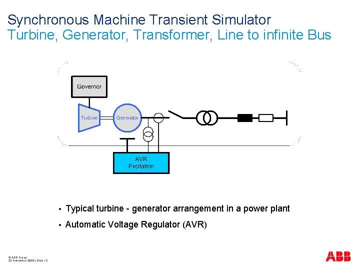
Synchronous Machine Transient Simulator Turbine, Generator, Transformer, Line to infinite Bus © ABB Group 23 November 2020 | Slide 12 § Typical turbine - generator arrangement in a power plant § Automatic Voltage Regulator (AVR)
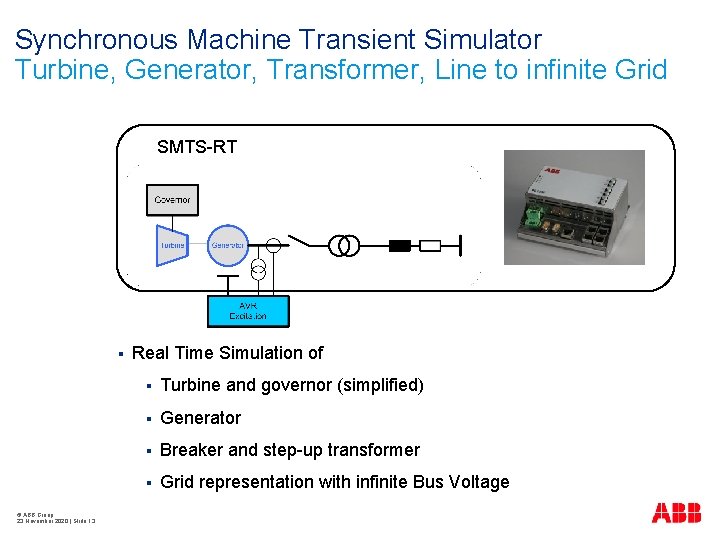
Synchronous Machine Transient Simulator Turbine, Generator, Transformer, Line to infinite Grid SMTS-RT § © ABB Group 23 November 2020 | Slide 13 Real Time Simulation of § Turbine and governor (simplified) § Generator § Breaker and step-up transformer § Grid representation with infinite Bus Voltage
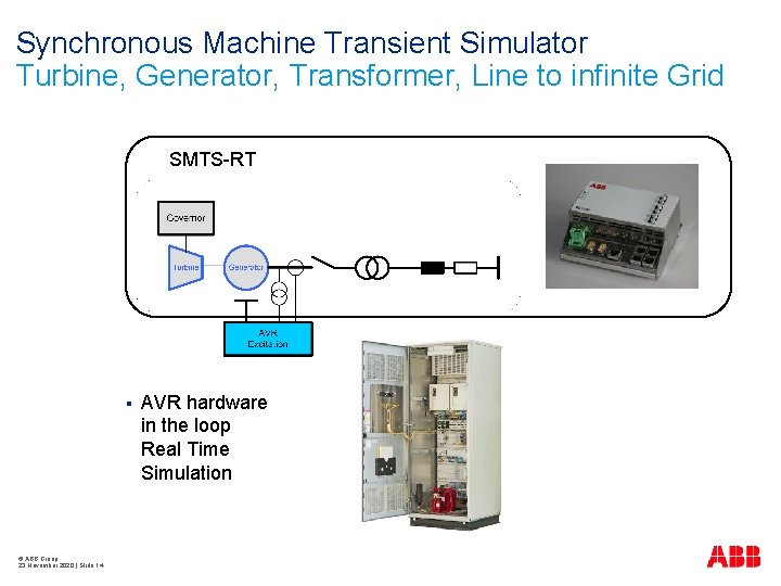
Synchronous Machine Transient Simulator Turbine, Generator, Transformer, Line to infinite Grid SMTS-RT § © ABB Group 23 November 2020 | Slide 14 AVR hardware in the loop Real Time Simulation
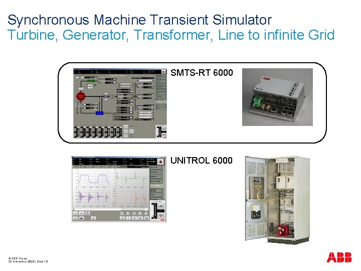
Synchronous Machine Transient Simulator Turbine, Generator, Transformer, Line to infinite Grid SMTS-RT 6000 UNITROL 6000 © ABB Group 23 November 2020 | Slide 15
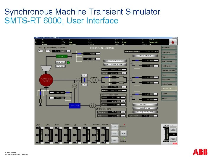
Synchronous Machine Transient Simulator SMTS-RT 6000; User Interface © ABB Group 23 November 2020 | Slide 16
OUTLINE Controlled Generator on Grid § The main functions of an Automatic Voltage Regulator (AVR) § The main functions of a Power System Stabilizer (PSS) How to test an AVR system § Introduction to Real Time Simulator Grid Code compliance testing § © ABB Group 23 November 2020 | Slide 17 UNITROL built in compliance test functions
AVR Grid Code Compliance Grid Code Example Excerpt from of a local grid code: “Overall Excitation System Control Characteristic …The frequency domain tuning of the Power System Stabilizer shall also be demonstrated by injecting a 0. 2 Hz-2 Hz band limited random noise signal into the Automatic Voltage Regulator reference… while the Generating Unit is operating at a typical load level. . . …The damping contribution of the Power System Stabilizer shall improve the system-stability within the frequency-band of interest (compared to the system response without a stabilizer): i. e. , 0. 2 Hz - 2 Hz” © ABB Group 23 November 2020 | Slide 18
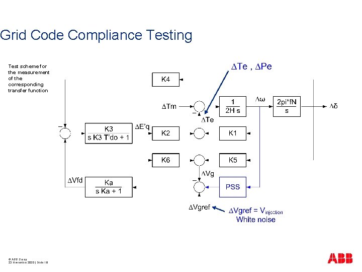
Grid Code Compliance Testing Test scheme for the measurement of the corresponding transfer function © ABB Group 23 November 2020 | Slide 19
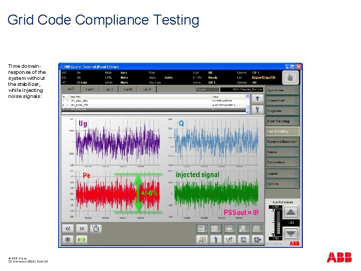
Grid Code Compliance Testing Time domainresponse of the system without the stabilizer, while injecting noise signals: © ABB Group 23 November 2020 | Slide 20 Expert. Days 09
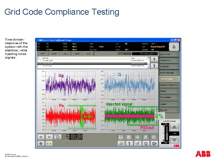
Grid Code Compliance Testing Time domainresponse of the system with the stabilizer, while injecting noise signals: Expert. Days 09 8% © ABB Group 23 November 2020 | Slide 21
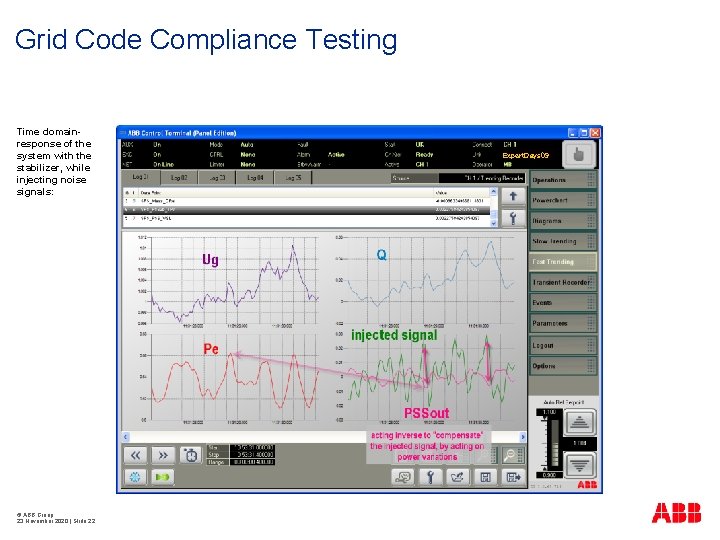
Grid Code Compliance Testing Time domainresponse of the system with the stabilizer, while injecting noise signals: © ABB Group 23 November 2020 | Slide 22 Expert. Days 09
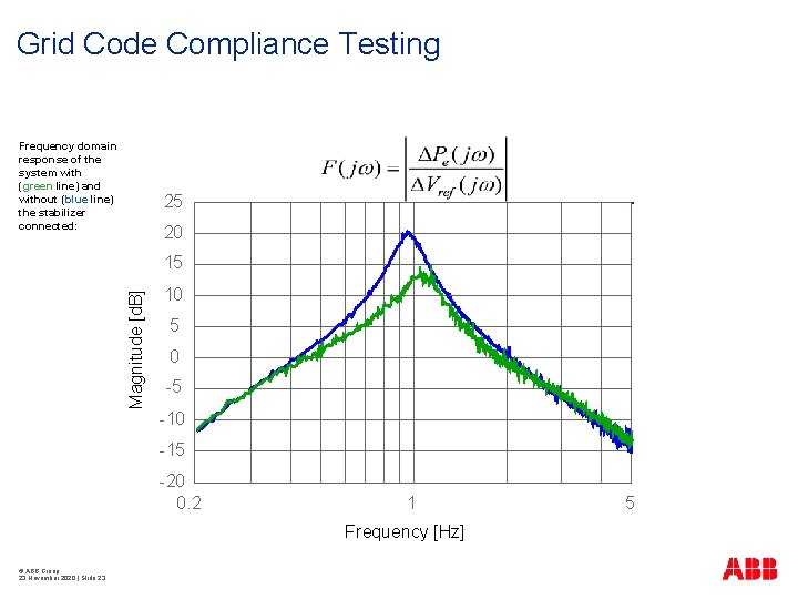
Grid Code Compliance Testing Frequency domain response of the system with (green line) and without (blue line) the stabilizer connected: 25 § 20 Magnitude [d. B] 15 10 5 0 -5 -10 -15 -20 0. 2 1 Frequency [Hz] © ABB Group 23 November 2020 | Slide 23 5
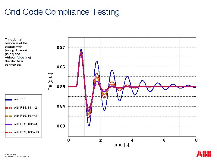
Grid Code Compliance Testing Time domain response of the system with (using different gains) and without (blue line) the stabilizer connected: 0. 87 Pe [p. u. ] 0. 86 0. 85 w/o PSS with PSS, KS 1=2 0. 84 with PSS, KS 1=3 with PSS, KS 1=4 0. 83 with PSS, KS 1=10 0 © ABB Group 23 November 2020 | Slide 24 2 time [s] 4 6 8

© ABB Group 23 November 2020 | Slide 25
- Slides: 25