RTOS Unit 5 Resources limayesir wordpress com Raj


 is a set of programs responsible")


{ while(1){ Temp = ADCport; //read ADC value OSMbox.")
 • TCB is a data structure associated with")


 – Inter")


 – Cooperative Scheduling in the cyclic order –")


}*N + t. ISR. • t ISR")


 • Fixed priority based schemes are like a traffic signal")


 • If different tasks have to run in a coordinated")
 function.")


 function─ task waits for the occurrences of setting all")


, OSSem.")
 { OS_ERR")


 { while (1) { ---------")
 • A deadlock, also called a deadly embrace, is a")

─ To delay the process for n ticks. •")

Create and specify the operating mode of the timer. •")


 fairly simple")


- Slides: 89
RTOS Unit 5 Resources: limayesir. wordpress. com Raj Kamal Heath
What RTOS? • Operating systems are software environments that provide a buffer between the user and the low level interfaces to the hardware within a system. They provide a standard interface and a set of utilities to enable users to utilise the system. Some applications do not require any operating system support at all and run direct on the hardware. They are called “Bare Metal” systems. • Real Time Operating System is a multitasking operating system for applications that need to meet time deadlines for operations and have a constraint on time taken to respond to an event. • RTOS has two main parts: – Kernel for task management and inter task communication and coordination – Support services like device drivers, file system, memory management
Types of Real Time Systems • Hard Real Time Systems – Meeting deadlines is very critical and missing the target can result in catastrophic losses to life and property. The latencies can be deterministically calculated. E. g. Air bag control in cars, anti-lock brake, engine control system • Soft Real Time Systems – These systems also have deadlines but they are not very stringent. Missing them results in minor inconvinience to the user or a slight degradation of performance. E. g. Digital camera, mobile phones, online data base.
What is “Task”? • Task (also called process) is a set of programs responsible for one aspect of a system. E. g. one task is to periodically read temperature from a sensor. Another task is to transmit these temperatures on internet and update these values on cloud. • A task has 3 main states – Running (Only one can be running in a single processor system) – Ready (Waiting for its turn) – Blocked (Because it is waiting for some essential input)
Task life time • On booting, RTOS gets initialized and then it creates a master user task. This task creates more tasks and they all run in time sliced manner. • Some tasks are temporary and they are terminated once their function is over. • Some tasks are active throughout the life of the system. • On creation, every task is assigned a Task Control Block (TCB) which stores its state. It is in “Idle” state. When it is activated, it goes to “Ready” state. When a task is finished, its TCB is deallocated and it no longer exists.
Task coding • A task cannot call another task. The initial calling will be done by the scheduler. It may pass some parameters which will be stored in TCB. • As the task is endless, it is not expected to return. Hence it will be of void type. • Task code must be reentrant. i. e. no global variables. • If two or more tasks share a common data area, appropriate measures are taken to avoid conflict.
Example of tasks void task. Sense(){ while(1){ Temp = ADCport; //read ADC value OSMbox. Post(&Temp); //Post it on mailbox OSFlag. Pend(Timer. Flag); //Wait for next timer tick } } void task. Send(){ while(1){ Temp = OSMbox. Pend(); //Wait for message & read Update. Cloud(Temp); //Send temp to cloud } }//Note simplified versions of u. C/Osiii function are shown
Task control Block (TCB or PCB) • TCB is a data structure associated with each task that maintains information about the task. Various elements of TCB are: • State – Ready/Running/Blocked • Context – CPU registers incl. flags, SP, PC • Task ID, parent ID, Child ID • Allocated memory blocks and page table start address • Security and permissions
Thread • Thread is a sequentially executable code. • It can be considered as a lightweight task as the Thread Control Block is simpler than TCB because It uses resources of the parent task. • One task may have single or multiple threads. Threads are scheduled and managed by process. • Thread has states, (Running/Ready/Blocked), priority, stack space, context, masking flag
ISR • ISR is invoked on occurrence of a hardware signal or software instruction like SWI. • It first saves the registers that it is going to use • It performs input/output operation and resets the interrupt condition. Enables interrupt system. • It does not perform time consuming processing on I/O data. It posts a message to interrupt service task (IST) or any other task that is waiting for it. • ISR is not allowed to use any blocking statement like OSSem. Pend() or a wait loop as it will increase latency for other interrupt sources, because RTOS has to give guaranteed latency to other interrupts and tasks. • After performing I/O, it restores registers and returns. • Scheduler has no control over its execution. • Scheduler itself is invoked by timer interrupt.
RTOS services • RTOS offers its services in the form of API (Application Program Interface) which is a set of functions that can be called by application programs. E. g. OSTask. Create() is used to create a task. • We can broadly divide the services in two categories – Kernel for process management and IPC – Device drivers and file managers
services • Process management – Task creation and deletion – Scheduling (Despatching) – Inter process communication (Semaphores, messagesboxes, events, pipes, queues) – Timer functions • Other services – Device drivers like TCP/IP stacks, USB stacks, Graphic display, ISRs. – File system managers which provide functions like open, read, write and close.
Processor modes • Processor has two modes of operation – User mode – Kernel mode • In user mode, some instructions are disabled (e. g. Disabling or enabling interrupts) and some memory areas are not accessible. • Kernel mode has full control over the processor. • User mode threads run slower because they undergo various checks. Also when they call kernel services, mode is switched and time is lost.
Kernel architecture types 1 Monolithic kernel- All OS functions run in Kernel mode 2 Micro kernel – Only basic functions in kernel mode 3 Hybrid kernel – IPC and device drivers in kernel mode
Difference between RTOS and GPOS • RTOS uses preemptive scheduling to ensure that high priority task gains access quickly. GPOS uses non preemptive, i. e. cooperative scheduling to minimize task switching overhead. • RTOS scheduler uses algorithms like Earliest Deadline First (EDF) so that deadline is not missed. • Unlike RTOS, there is no priority inversion in GPOS.
Scheduling models • Cooperative (Tasks cooperate) – Cooperative Scheduling in the cyclic order – Cooperative Scheduling according to priority – Cyclic scheduling – Round robin time slicing • Preemptive (Tasks are switched fast) – Earliest Deadline First – Rate monotonic
Cooperative Scheduling in the cyclic order • Each task cooperates to let the running task finish or blocking stage. i. e. running task is not interrupted. • The service is in the cyclic order for all tasks in the “READY” list. This is equivalent to assigning rotating priorities, i. e. the task which has just finished gets lowest priority. • Task switching takes place when one task has finished and is waiting for something to happen. • Simple to implement.
Disadvantage • Worst case latency is same for every task, i. e. sum of execution times (eti) and switching time (sti) of all tasks and total time for ISRs. • Tworst = {(sti + eti )1 + (sti + eti )2 +. . . + (sti + eti )N-1 + (sti + eti )N} + t. ISR. • This may not be acceptable for some tasks.
Cooperative Scheduling according to priority • In this scheme, the “READY” list is ordered according to priority and the control is given to the highest priority task. • Thus the latency for high priority tasks is reduced. For highest priority task it is, • Tbest = (dti + sti + eti ) p(m)} + t. ISR • Where dti is event detection time • Worst case latency is for lowest priority task. It is, • Tworst {(dti + sti + eti )p 1 + (dti + sti + eti ) p 2 +. . . + (dti + sti + eti ) p(m-1) + (dti + sti + eti ) p(m)} + t. ISR. • Every task must meet the condition • Tworst < Td (Time Deadline)
Automatic chocolate vending machine • It has three tasks. – Sense the coins inserted by the user. (Highest priority) – Deliver chocolate. (Medium priority) – Display message ‘thank you, visit again’. (Lowest priority) • We can use cooperative Scheduling according to priority
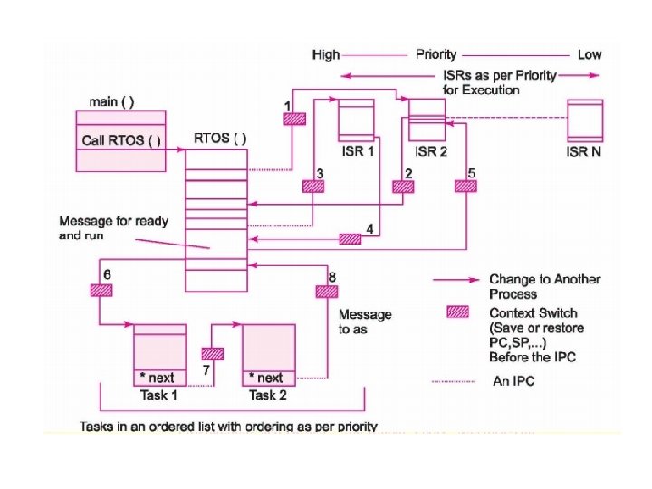
Tasks and ISR together • There are two layers of execution. ISR is in the first layer and it executes immediately. ISR quickly performs I/O and passes the message to Interrupt Service Task (IST). This puts IST in ready list and it does processing of the message. • The tasks run in the second layer according to their priorities. Priority of interrupts is decided by hardware and corresponding IST has same priority.
Cyclic scheduling • This is suitable for a small number of periodic tasks. Assume that we have three tasks that need to be executed after every Tcycle seconds. • The first task executes at t 1, t 1 + Tcycle, t 1+ 2 * Tcycle, … • second task executes at t 2, t 2 + Tcycle, t 2+ 2 * Tcycle and • Third task at t 3, t 3 + Tcycle, t 3+ 2 * Tcycle, … • Timer function of RTOS is used for this purpose.
Latency in cyclic scheduling • Tcycle is chosen such that • Tcycle = N * Sum of the maximum times for each task • Each task is executed once and finishes in one cycle itself. When a task finishes the execution before its maximum time, there is an idle period in-between period between two cycles. • If the tasks are fired in a staggered manner, then there is no waiting period. In the worst-case, all tasks are fired at the same time. In this case, • latency = N * Sum of the maximum times for each task. • A task’s need of repeat execution is an integral multiple of tcycle.
Example of Video and audio signals • Signals reach at the ports in a multimedia system in MP 3 format. They converted to bitmap format suitable for displaying on LCD screen. • The video frames arrive at the rate of 25 frames per second. • The cyclic scheduler is used in this case to process video and audio with Tcycle = 40 ms or in multiples of 40 ms.
Round robin with time slicing • This scheme is a hybrid between cooperative and preemptive scheduling. It minimizes switching while achieving low latency. • Each task in ready list runs in a cyclic queue but it gets a limited time period (Tslice)to execute. If the cycle period is Tcycle, and there are N ready tasks, then Tslice = Tcycle / N seconds. • If the task is not finished within its slice, then it is interrupted and control is given to the next task. It will do the unfinished job in the next one or more cycles.
Latency of round robin • Tcycle ={Tslice )}*N + t. ISR. • t ISR is the sum of all execution times for the ISRs, i = 1, 2, …, N -1 , N • Tworst = N *(Tslice) + t. ISR. • Worst case latency is same for every task in the ready list.
Preemptive scheduling • GPOS uses cooperative scheduling to minimize switching overhead, • In cyclic scheduling, Worst case latency equals the sum of execution times of all tasks. • In priority based scheduling a long execution time of a low- priority task lets a high priority task wait till it finishes. • RTOS always uses preemptive scheduling to achieve low latency. • Scheduler is triggered at periodic intervals with system timer. With each invocation, it schedules the task having highest priority in the ready list. If the highest priority task is other than the current task, then task switching takes place.
Preemptive with Fixed priorities • A long low priority task does not keep high priority task waiting. Maximum wait is Tslice, i. e. clock tick period. • At every clock tick, scheduler provides for preemption of lower priority process by higher priority process. • Assume priority of task_1 > task_2> task_3 > task_4…. > task N • Each task has an infinite loop from start (Idle state) up to finish.
Assigning priorities • Priorities are assigned by the programmer during programming phase depending on the relative importance. Scheduler cannot change them. • For example, – Highest priority for “panic” pushbutton. – Power fail detection is next priority – Print events log (Soft deadline) – Run system diagnostics (lowest priority)
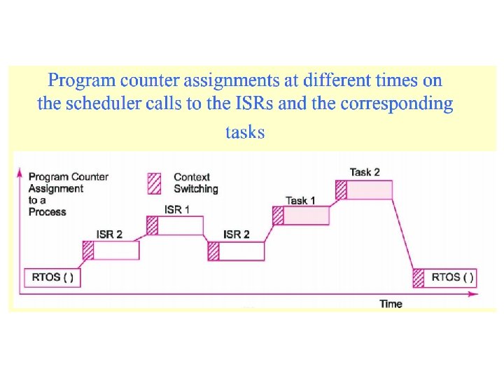
Preemptive fixed priority scheduling
Program counter assignment • Initially Task 2 is running. • At clock tick, OS preempts Task 2 and runs higher priority task 1. • Task 1 is highest priority, so it runs to completion and yields control to OS • Task 2 resumes where it left and completes. • Another ready task 3 takes over
Earliest Deadline First (EDF) • Fixed priority based schemes are like a traffic signal without traffic sensors. They do not have actual control over deadlines. • EDF algorithm assigns dynamic priorities based on time of deadline. The task having earliest deadline is assigned highest priority. It may also have two or more priority queues where tasks could be inserted. • Example Task. Release time Compute Time Ci Deadline Period Ti T 1 0 1 4 4 T 2 0 2 6 6 T 3 0 3 8 8
EDF example • • • 1. First let us see schedulability. CPU utilization U is given by S Ci / Ti U= 1/4 +2/6 +3/8 = 0. 25 + 0. 333 +0. 375 = 0. 95 = 95% Since U < 1, schedule is feasible. At t=0 all the tasks are released, but priorities are decided according to their absolute deadlines so T 1 has higher priority as its deadline is 4 earlier than T 2 whose deadline is 6 and T 3 whose deadline is 8, that’s why it executes first.
• • At t=1 again absolute deadlines are compared and T 2 has shorter deadline so it executes and after that T 3 starts execution but at t=4 T 1 comes in the system and deadlines are compared, at this instant both T 1 and T 3 has same deadlines so ties are broken randomly so we continue to execute T 3. At t=6 T 2 is released, now deadline of T 1 is earliest than T 2 so it starts execution and after that T 2 begins to execute. At t=8 again T 1 and T 2 have same deadlines i. e. t=16, so ties are broken randomly an T 2 continues its execution and then T 1 completes. Now at t=12 T 1 and T 2 come in the system simultaneously so by comparing absolute deadlines, T 1 and T 2 has same deadlines therefore ties broken randomly and we continue to execute T 3.
• • • At t=13 T 1 begins it execution and ends at t=14. Now T 2 is the only task in the system so it completes it execution. At t=16 T 1 and T 2 are released together, priorities are decided according to absolute deadlines so T 1 execute first as its deadline is t=20 and T 3’s deadline is t=24. After T 1 completion T 3 starts and reaches at t=17 where T 2 comes in the system now by deadline comparison both have same deadline t=24 so ties broken randomly ant we T continue to execute T 3. At t=20 both T 1 and T 2 are in the system and both have same deadline t=24 so again ties broken randomly and T 2 executes. After that T 1 completes it execution. In the same way system continue to run without any problem by following EDF algorithm.
Rate monotonic algorithm • This is a fixed priority algorithm in which task priorities are assigned according to their rate of arrival. Priority of a task is proportional to its arrival rate. Task with Highest frequency has highest priority and the task with lowest frequency will have lowest priority. • Its disadvantage is that sporadic and aperiodic tasks are not supported. Sporadic tasks may arrive at a high frequency during burst period but they will have low priority. This problem is solve by assigned tickets, i. e. special slots to sporadic tasks. • Another disadvantage is that a task may have a low frequency but its deadline may be critical. This is solved by splitting such task into two or more subtasks.
• Advantages of EDF over rate monotonic • No need to define priorities offline • It has less context switching than rate monotonic • It utilize the processor maximum up to 100% utilization factor as compared to rate monotonic • Disadvantages of EDF over rate monotonic • It is less predictable. Because response time of tasks are variable and response time of tasks are constant in case of rate monotonic or fixed priority algorithm. • EDF provided less control over the execution • It has high overheads
Context switching • Context refers to the CPU state, namely registers, including SP, PC, Flags. When interrupt occurs, ISR saves the context on stack. At the end, ISR pops the context from stack. When PC is restored, the interrupted program resumes. • In preemptive scheduler RTOS, task switching occurs At Sys. Tick intervals. The hardware clock interrupt saves the context of the running program on stack. But at the end, control is not given back to the interrupted program. Control goes to OS. It copies the context to TCB and also stores its current state and other information. The OS updates message Pend and Post functions, updates the READY/BLOCKED states of all tasks. Then the scheduler is run to determine the next task to be run. If it is different from the interrupted task, then Page table base address is updated for the new task and its context is copied from its TCB to stack as if it was interrupted. Then RETI instruction causes it to resume.
Inter process communication (IPC) • If different tasks have to run in a coordinated manner, then they should be able to communicate with each other. RTOS provides several mechanisms for this. • Message queue • Mailbox • Pipe and socket • Signal and event
Message queue • A task can create one or more queues with OSQCreate() function. Each queue has a unique ID. The maximum queue length is specified during creation. • OSQPost() function is used to put data in FIFO queue. • OSQPost. Front() function is used to put data in LIFO queue. • OSQPend() is used to wait for a message and read it and remove it from the queue. • There may be multiple receivers of the message. • The queue entries may be data or pointer to data.
mailbox • Mailbox is similar to queue. • It is used to send data from one task to another. • It can contain only one entry whereas queue can contain FIFO or LIFO queue. • The API functions are – OSMBox. Create() – OSMBox. Post() – OSMBox. Pend()
Using messagebox or queue for sequencing of tasks
pipe • Pipe is another inter process communication mechanism but unlike message queue and mail box, it is like a byte stream and accessed like file functions. • Pipe is unidirectional. One thread or task inserts into it and other one deletes from it. • Pipe has the functions pipe. Dev. Create , connect and delete and functions. • A has a variable number of bytes per message between the initial and final pointers. • Data transfer is done similar to a file (open, write, read, close)
Pipe example
signal • Signal is used to synchronize two processes without the need for sending any data. It is shortest and fastest method compared to message box or message queue. • signal( ) function is Provided in Unix, Linux and several RTOSes. It is software equivalent of interrupt and it causes execution of “Signal handler”. Each signal has an ID number. A vector table indexed by ID is used to find the address of corresponding signal handler. • Signal bypasses the scheduler mechanism and passes the event immediately.
Event Functions • Semaphore or mailbox-message posting functions wait for only one event. • Event related OS functions are more flexible. Using event function, a tasks can wait for number of events to occur or wait for any of the predefined set of events. • Events for wait can be from different tasks or the ISRs. • OSEvent. Create ( ) creates an event register containing 8, 16 or 32 bits. Each bit corresponds to an event flag. We can form groups of the bits so that wait can be for all flags in a group or for any flag in a group. • SET (event_flag) is used to set and CLEAR(event_flag) is used to clear flag.
Types of wait • WAIT_ALL() function─ task waits for the occurrences of setting all the event flags in a group. [Wait till AND operation between all flags in the group equals true. ] • WAIT_ANY() function─ task waits for the occurrences of setting at least one event flag setting in a group. [Wait till OR operation between all flags in the group equals true. ]
Sharing data • We need to share a memory block among two or more processes for following reasons. • Time, which is updated continuously by a process, is also used by display process in a system � • Port input data, which is received by one process and further processed analysed by another process. � • Memory Buffer data which is inserted by one process and further read (deleted), processed analysed by another process
Shared data problem • Consider that one task is updating the shared data block and it gets preempted before the complete update is finished. Then control goes to another task which is reading the block. • Now the reading task will get partially old and partially new data. This can cause problem. For example, consider that a timer task is updating time from 10: 59 to 11: 00. • When it updated minutes to 00, it got preempted. The reading task now will read the time as 10. 00.
Solution to shared data problem • A set of operations that should be executed without interruption is called “Critical Section”. This set is also called “atomic operation”. • Following methods are available to combat this problem – – Disabling interrupts Declaring Critical section Using message queue Using Semaphores
Disabling interrupts • Task switching occurs when scheduler is invoked in response to clock tick interrupt. • A simple way to ensure that the task is completed is to disable interrupt using DI instruction. In ARM, we can set IRQ mask bit. After the completion of the atomic operation interrupts are reenabled. • The disadvantage of this scheme is that interrupts remain disabled for a long time, so even if interrupt of a priority higher than the current task occurs, it will remain pending.
Critical section • Instead of disabling the whole interrupt system, we can inform the OS that a task is handling an atomic operation as follows. • CPU_CRITICAL_ENTER() – -----– Atomic code – ----- • CPU_CRITICAL_EXIT() • If a clock tick interrupt occurs in critical section, OS will not switch the task till the task calls CPU_CRITICAL_EXIT() function. • Some RTOSes use lock() and unlock() for this purpose.
Using message queue • Pass the shared variable block in message queue. • The receiving task always deletes (takes) it from the queue front. • The sending task inserts (writes) the value of this variable, always does so at the queue back. If it gets interrupted when it has written the message halfway, it completes it after gaining the control back.
Using semaphores • This is a still better method because it locks neither interrupts nor the scheduler. It locks just the reader task. • The word “Semaphore” is derived from old railway signalling system. In that system, semaphore was a token which a train must posses for using a section of track. On leaving the section, the semaphore is returned. • Similarly for using a memory block, a task must first ask for a semaphore. If available, it will be given by the RTOS and then the task can go ahead and change the memory block. During this time, if another task asks for the semaphore, it will be denied and it will get blocked. After the job is over, the task returns the semaphore. If any task is pending for this semaphore, it gets unblocked.
Uses of semaphores • For synchronization – i. e. initiate another task when some event has occurred. E. g. reception of a data byte should trigger processing of the byte. • For mutual exclusion – Allow only one task to use a resource at a time. This called a binary semaphore because it uses only values 0 and 1. It has problem of priority inversion which is solved by Mutex. • For resource management – Sometimes a pool of resources (e. g. N memory buffers) is available and it could be used by upto N tasks. The semaphore keeps a count of user tasks. This is called counting semaphore.
Uc/os iii semaphore services A task creates and deletes a semaphore. OSSem. Create(), OSSem. Delete(). Semaphore is a named struct in task code. Task or ISR can use OSSem. Post() for synchronization. Semaphore maintains a count of how many times it as called (N). Receiving task ues OSSem. Pend() to wait for semaphore. It can use optional feature of Time out. If time out occurs, it ill take some corrective action
Uc/os code for creating semphore OS_SEM My. Sem; void My. Code (void) { OS_ERR err; : OSSem. Create(&My. Sem, “My Semaphore”, (OS_SEM_CTR)0, &err); /* Check “err” */ : }
Typical application of synchronization 1. High priority task initiates IO and pends 2. Control goes to scheduler. 3. Scheduler decides next task 4. Scheduler switches task 5. Low priority task runs 6 ISR runs on completion of IO. 7 ISR sends OSSem. Post() 9 Scheduler runs 10 Scheduler switches task 11 High priority task resumes
Using semaphores to cyclically invoke 4 tasks
Credit Tracking semaphore • As previously mentioned, a semaphore “remembers” how many times it was signaled (or posted to). In other words, if the ISR occurs multiple times before the task waiting for the event becomes the highest-priority task, the semaphore will keep count of the number of times it was signaled. • When the task becomes the highest priority ready-to-run task, it will execute without blocking as many times as there were ISRs signaled. • This is called Credit Tracking
Credit tracking semaphore example
Counting semaphore example • Assume that a task can send data on a network through 8 buffers. • Assume that a counting semaphore scnt is initialized = 8. � • Each time the task is ready with data, it takes the counting semaphore scnt. OS decrements scnt. The task sends the data to one of the buffers. • When a task tries to take the scnt when it is 0, then the task blocks and cannot send data into the buffer
P and V semaphores • Some operating systems use P and V functions to implement counting semaphores. Semaphore Sem is an integer and it is initialized to an initial value. • P(&Sem) is used to access the semaphore. The task decrements it and If it becomes negative, blocks by using function wait. Call. To. OS(&Sem). • V(&Sem) used to access and increment a semaphore after use.
Problems with semaphores • While semaphores solve the mutual exclusion problem, they create two new problems – Priority inversion: When a low priority task takes a semaphore which later requested by a high priority task, it has to wait till the low priority task finishes. – Deadlock: When two tasks require multiple resources and each task has acquired some of the needed resources, none can go to completion and they keep waiting for each other indefinately.
Priority inversion • Consider 3 tasks, I, J, K in decreasing order of priority. I and K share a common resource and hence they are protected by a semaphore. • At time t 0, task K takes the semaphore. • At time t 1 task J preempts task K • At time t 2 task I requests semaphore but it has to wait till the low priority task K finishes.
Solution of priority inversion • The priority inversion problem can be solved by the mechanism of priority inheritance. • In this mechanism, whenever a high priority task requests a semaphore held by a low priority task, the low priority task inherits the priority of the high priority task so that it can complete its operation without being prempted by other higher priority tasks. • It is recommended to use Mutex (Mutual Exclusion) instead of semaphore. Mutex is a binary semaphore which automatically implements priority inheritance and avoids the priority inversion problem.
Mutex functions in uc/os void Task 1 (void *pdata) { while (1) { --------- Application Code --------- OSMutex. Pend(Resource. Mutex, 0, &err); ------- Access common resource ----- OSMutex. Post(Resource. Mutex); --------- Application Code --------- } }
Deadlock (or Deadly Embrace) • A deadlock, also called a deadly embrace, is a situation in which two tasks are each unknowingly waiting for resources held by the other. Assume task T 1 has exclusive access to resource R 1 and task T 2 has exclusive access to resource R 2. If T 1 further needs exclusive access to R 2 and T 2 further needs exclusive access to R 1, neither task can continue. They are deadlocked. The simplest way to avoid a deadlock is for tasks to • acquire the resources in the same order, and • release the resources in the reverse order. • You to specify a timeout when acquiring a semaphore. If the semaphore is not available within a certain amount of time, the task requesting the resource resumes execution. Some form of error code must be returned to the task to notify it that a timeout occurred.
Time Functions • All time and timer functions are based on Sys. Clk. Intr interrupt. Timer ISR must be coded in assembly language and it should call OS function Sys. Clk. Intr. • OSInit ( ) function calls OSTick. Init ( ) to set the frequency of scheduler interventions. OSTick. Init ( ) function uses the constant • # define OS_TICK_PER_SEC 100 • It sets the parameters of counter/timer such that interrupts occur 100 times a second, i. e. at 10 ms intervals • By increasing timer tick frequency, worst case latency is reduced but more CPU time is wasted in task switching. We need to achieve a balance.
Time functions • OSTime. Delay (n)─ To delay the process for n ticks. • OSTime. Delay-Resume (task ID)─ to resume a delayed process specified in the argument • OSTime. Set (n)─ to set the counts of system clock ticks • OSTime. Get ( ) ─ to read the counts of system clock ticks • Recover from all Pend functions with a timeout like OSSem. Pend
Timer • Timers are down counters that callback, a userdeclared function that will be called when the timer expires. It is important to never make blocking calls within a callback function. i. e. call OSTime. Dly(), OSTime. Dly. HMSM(), OS? ? ? Pend(). Timers are useful in protocol stacks (re-transmission timers, for example), and can also be used to poll I/O devices at predefined intervals. OS_TMR OSTmr. Create (INT 32 U dly, /* Initial delay */ INT 32 U period, /* Repeat period */ INT 8 U opt, /* Options */ OS_TMR_CALLBACK callback, /* Fnct to call void *callback_arg, /* Arg. to callback */ CPU_CHAR *pname, /* Name of timer, */ INT 8 *perr)
Timer functions • OSTmr. Create()Create and specify the operating mode of the timer. • OSTmr. Del()Delete a timer. • OSTmr. Remain. Get()Obtain the remaining time left before the timer expires. • OSTmr. Start()Start (or restart) a timer. • OSTmr. State. Get()Obtain the current state of a timer. • OSTmr. Stop()Stop the countdown process of a timer.
Uc/os • Jean J. Labrosse designed it in 1992 • µC/OS-II name derives from Micro. Controller Operating System • Also known as MUCOS and UCOS. Currently uc/os iii is available. • Features • Preemptive RTOS • Multitasking • Deterministic • Portable as ROM image • Scalable (Only needed functions are linked) • Different Platforms support • It is freeware. Full source code availability from www. micrium. com
Uc/os applications • It has a pre-certifiable software component for safety critical systems, including avionics system clock. A DO 178 B and EUROCAE ED-12 B, medical FDA 510(k), and IEC 61058 • Application areas • Automotive, � • avionics, � • consumer electronics, � • medical devices, � • military, � • aerospace, � • networking • We have already discussed various functions.
Porting of uc/os • Uc/os is written in a modular manner. The kernel functions like scheduling and IPC are written in C. They need not be changed from one processor to another. • There are 3 hardware dependant files – – OS_CPU. h(CPU and compiler specific information) OS_CPU_A. ASM (Timer and task switching) OS_CPU_C. C (Hooks for RTOS functions) OS_CFG. h (Tells which features of OS are required) • These files have to be written for a specific processor, compiled and linked with the rest. • The compiler should be ANSI C. Assembler is also required for saving registers and interfacing clock tick generator.
OS_CPU. h • Because different microprocessors have different word lengths, the port of µC/OS-II includes a series of type definitions that ensures portability. Specifically, µC/OS-II code never makes use of Cs short, int, and long data types because they are inherently nonportable. • EXAMPLES typedef unsigned char BOOLEAN; typedef unsigned char INT 8 U; /* Unsigned 8 bit quantity */ typedef signed char INT 8 S; /* Signed 8 bit quantity */ typedef unsigned int INT 16 U; /* Unsigned 16 bit quantity */ typedef signed int INT 16 S; /* Signed 16 bit quantity */ typedef unsigned long INT 32 U; /* Unsigned 32 bit quantity */ typedef signed long INT 32 S; /* Signed 32 bit quantity */ typedef float FP 32; /* Single precision floating point */ #define OS_ENTER_CRITICAL() DI /* Disable intr*/ #define OS_EXIT_CRITICAL() EI /*enable interrupts*/ #define OS_STK_GROWTH 1 /* Stack growth (0=Up, 1=Down) */
OS_CPU_C. C • A µC/OS-II port requires that you write ten (10) fairly simple C functions: • OSTask. Stk. Init() OSTask. Create. Hook() OSTask. Del. Hook() OSTask. Sw. Hook() OSTask. Idle. Hook() OSTask. Stat. Hook() OSTime. Tick. Hook() OSInit. Hook. Begin() OSInit. Hook. End() OSTCBInit. Hook() • The only required function is OSTask. Stk. Init(). The other nine functions must be declared but may not need to contain any code. • OSTask. Stk. Init() function is called by by OSTask. Create() to initialize the stack frame of a task so that the stack looks as if an interrupt just occurred and all the processor registers were pushed onto that stack.
OS_CPU_A. ASM • A µC/OS-II port requires that you write four assembly language functions: • OSStart. High. Rdy() • OSCtx. Sw() • OSInt. Ctx. Sw() • OSTick. ISR() • If your compiler supports in-line assembly language code, you could actually place these functions in OS_CPU_C. C instead of having a separate assembly language file.
Memory management • Some embedded processors are designed to execute from Flash ROM. In these processors, RTOS and application programs are statically linked and downloaded into target processor. E. g. Arduino and ARM coretx M series. The RAM allocation for stack and data is done by the linker and it is not changed during operation. However tasks may require additional memory buffers from time to time and they return these buffers when the job is over. For this purpose, they may use malloc() function but it leaves holes in memory and allocation becomes difficult. • RTOS memory management functions provide a more robust and efficient alternative.
Memory management • Some processors like ARM cortex A series are meant to be used with RT Linux. Here OS and application programs are separately complied and linked. They are loaded in RAM from Flash and then executed. Each program assumes that it starts from address 0. In this case, MMU is necessary to translate logical address to physical address. • RTOS services are needed for both initial allocation and subsequent allocation during operation. It also needs to fill the MMU page tables with physical memory addresses and switch page table base address when a task switch occurs.
Memory allocation • When a process is created, the memory manager allocates the memory addresses (blocks) to it by mapping the process logical address space to physical space. • Threads of a process share the memory space of the process. • Memory manager of the OS is secure, robust and well protected. It ensure that there are no memory leaks, unauthorized accesses and stack overflows.
Memory Managing Strategy • • Fixed-blocks allocation Dynamic -blocks Allocation Dynamic Page-Allocation Dynamic Data memory Allocation Dynamic address-relocation Multiprocessor Memory Allocation Memory Protection to OS functions
Mamory strategies • Fixed block allocation – A large continuous block of memory partition is created by OSMem. Create() function and it is divided into fixed size blocks which are allotted to tasks. We can have more than one partions of different sizes so that a task can choose a block of suitable size. • Dynamic block allocation – During operation, memory manager allocates variable sized blocks in multiples of 64 or 256 bytes to tasks. • Dynamic Page allocation – Pages of MMU are allocated to tasks and are managed by page tables.
Memory strategies • Dynamic data memory allocation – Memory manager allocates memory to data structures like list, queue and stack. • Dynamic address relocation – RTOS may move a block and adjust the relocation register (MMU page table) and limit register. • Multiprocessor memory allocation – Shared memory for tightly coupled processore (on same bus) or multi segment allocation for loosely coupled processors
Memory strategies • Memory protection for OS functions – OS function code, data and stack are in protected memory area. Application program is not allowed to access them • Memory protection among tasks – Separate memory spaces are allocated to tasks and one task cannot access memory of other task.
Uc/os memory functions Create a memory partition OS_MEM *OSMem. Create (void *addr, INT 32 U nblks, INT 32 U blksize, INT 8 U *err) Get a memory block void *OSMem. Get (OS_MEM *pmem, INT 8 U *err) Return a memory block INT 8 U OSMem. Put (OS_MEM *pmem, void *pblk) Enquire status of partition INT 8 U OSMem. Query (OS_MEM *pmem, OS_MEM_DATA *pdata)
End of UNIT 5