RPISYSTEM ESENTED BY DR ARIFA HASSAN DEPT OF

RPI-SYSTEM ESENTED BY DR ARIFA HASSAN DEPT OF PROSTHODONTICS

CONTENTS � INTRODUCTION � DEFINITIONS � REQUIREMENTS OF PROPERLY DESIGNED CLASP RETAINER � CONCEPTS OF RPI � KROLL’S SYSTEM q REST q PROXIMAL PLATE q I-BAR � THREE BASIC APPROACHES � MOUTH PREPARATION q REST SEAT q GUIDE PLANES � ADVANTAGES � CONTRA-INDICATION � MODIFICATIONS TO RPI � REVIEW OF LITERATURE � CONCLUSION � SUMMARY � REFERENCE

INTRODUCTION �One of the dentist’s most interesting and thought- provoking situations occurs when treatment requires a rigid prosthetic replacement which must be compatible with two different kinds of support. This situation exists in treatment with distal extension partial dentures.

�Removable partial denture can be tooth supported or tooth and tissue supported �In tooth supported RPD , a metal base or the framework that supports an acrylic resin base is connected to and is part of a rigid framework that permits the direct transfer of occlusal forces to the abutment teeth through the occlusal rests.

�The distal extension base RPD does not have this advantage of total tooth support one or more bases are extensions covering the residual ridge distal to the last abutment. �Therefore it is dependent on the residual ridge for the portion of its support.

�Problems associated with this type of prosthesis are much more than the problems associated with those that are either entirely tooth or tissue borne �Retention is not alone attained by clasp or direct retainers but also from indirect retainers.

Difference between a tooth borne and tissue borne removable partial denture �Support
 � A removable partial denture that")
Definitions �Extension base removable partial denture (GPT -8) � A removable partial denture that is supported and retained by natural teeth only at one end of the denture base segment and in which a portion of the functional load is carried by the residual ridge.
- that component of removable partial prosthesis used to retain and")
�Direct retainer (GPT 8)- that component of removable partial prosthesis used to retain and prevent dislodgment , containing of a clasp assembly or precision attachment
- the component of a partial removable dental prosthesis that assists")
�Indirect retainer (GPT 8)- the component of a partial removable dental prosthesis that assists the direct retainer in preventing displacement of the distal extension denture base by functioning through lever action on the opposite side of the fulcrum line when the denture base moves away from the tissues in pure rotation around the fulcrum

Terminology �REST : A rigid component of a removable partial denture which rests in a recessed preparation on the occlusal, lingual or incisal surface of a tooth to provide vertical support for the denture. Although a rest is a component of a direct retainer (retentive unit, clasp assembly), the rest itself is classified as a supporting element due to the nature of its function. �REST SEAT : A portion of a tooth selected and prepared to receive an occlusal, incisal or lingual rest

�I-bar clasp: the component of the clasp assembly that engages a portion of the tooth surface and either enters an undercut for retention or remains entirely above the height of contour to act as a reciprocating element. Generally it is used to stabilize and retain a removable dental prosthesis

REQUIREMENTS OF A PROPERLY DESIGNED CLASP RETAINER �Resistance to the vertical components of masticatory force which prevents the partial denture from being displaced toward the soft tissue. �It is provided by the occlusal rest. �Bracing (stabilization): the resistance to horizontal components of force. �It is provided by the rigid components of the clasp including the occlusal rest and the minor connector. Removable Partial Denture Manual Robert W. Loney, DMD, MS 2011

�Retention: the resistance to dislodgement in an occlusal direction. � It is provided by the clasp tip engaging the undercut when a dislodging force is applied. � Adequate Encirclement: The clasp assembly must engage more than 180º(more than half the circumference) to prevent the tooth from moving out or the clasp.
: Each force exerted on a tooth by a clasp arm must be")
�Receprocation(reciprocal action): Each force exerted on a tooth by a clasp arm must be offset by an equal and opposite (compensating) force. �This is provided by the reciprocal arm located on the opposite side of the tooth. � Normally the reciprocal arm does not engage an undercut.

� Passivity: when the clasp is in place on the tooth, it should be at rest. Its retentive function is activated only when a dislodging force is applied. �A force in an occlusal direction causes the retentive arm to engage the undercut from a gingival direction and so retain the partial denture in place. �The clasp should never "grip" the tooth

CONCEPTS OF RPI �R. P. I system was designed by Kratochvil in 1963. Krol in 1973 later developed a modification that avoids extensive tooth preparation. Although the system can be applied easily to the tooth borne partial dentures, discussion here is limited primarily to distal extension situation in order to demonstrate basic principles of design. Distal extension partial denture component have difficult assignment of making a transition from non-resilient (tooth) to resilient (mucosa) supporting structures without comprising either type of support. FUNDAMENTALS OF REMOVABLE PARTIAL PROSTHODONTIC DESIGN Kenneth R. Mc. Henry, D. D. S. , M. S. Terrence Mc. Lean, D. D. S.

�To weigh the merits of various designs, several methods of treatment must be studied and their effects on both hard and soft structures evaluated. Since the greatest difficulty occurs in the transition area where tooth support ends and mucosa support begins, i. e. , in the tooth-tissue region adjacent to the edentulous space, this discussion will be confined to the distal extension situation.
 the effect of the rotation or")
�Three basic aspects will be considered : �(1) the effect of the rotation or occlusal rest position on the soft and hard tissues, �(2) the effect of clasp design and placement on hard and soft tissues, and (3) considerations at the junction of the tooth and edentulous mucosa INFLUENCE OF OCCLUSAL REST POSITION AND CLASP DESIGN ON MOVEMENT OF ABUTMENT TEETH. . FRANK J. KRATOCHVIL; J. Pros. Den. Jan. . Feb. , 1963 Volun 1 e 13 Number 1

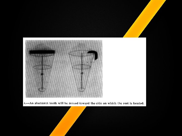
1. EFFECT OF THE ROTATION OR OCCLUSAL REST POSITION � Placement of an occlusal rest distally to the central axis of the posterior abutment tooth will tend to tip the teeth posteriorly. If the rest is placed on the mesio-occlusal surface, it will tend to tip the tooth mesially so it will receive support and bracing assistance from the teeth anterior to it. 1. INFLUENCE OF OCCLUSAL REST POSITION AND CLASP DESIGN ON MOVEMENT OF ABUTMENT TEETH. . FRANK J. KRATOCHVIL; J. Pros. Den. Jan. . Feb. , 1963 Volun 1 e 13 Number 1

�EFFECT OF CLASP DESIGN AND PLACEMENT When a circumferential clasp is placed on a tooth, the natural contour of the tooth in cross section is altered. Interference with the natural flow of food over the tooth and onto the gingiva results in loss of the tissue stimulation so necessary for healthy gingiva. This distortion of tooth form provides a space for food debris to accumulate between the clasp and the gingivae.

�A much more natural situation exists when an infrabulge I bar clasp is used. This type of clasp causes the least possible distortion of natural tooth contour and allows for natural food flow, gingival stimulation, and minimal contact of the clasp with the tooth.

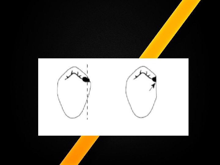
�The forces brought into play by different types of clasps on the distal abutment tooth. As the metal framework rotates around a mesio-occlusal rest, the mesial part of the clasp moves forward and slightly upward. It loses contact with the tooth and causes no adverse forces. The distal part of the clasp moves forward and downward. This seems to be acceptable until an occlusal view of the region is observed 1. INFLUENCE OF OCCLUSAL REST POSITION AND CLASP DESIGN ON MOVEMENT OF ABUTMENT TEETH. . FRANK J. KRATOCHVIL; J. Pros. Den. Jan. . Feb. , 1963 Volun 1 e 13 Number 1

�The distal part of the T bar wraps around the natural curvature of the tooth. Then, when the distal part of the clasp moves forward, it engages the distal curvature of the tooth and exerts a torquing effect which is most detrimental to the periodontal membrane.

�A solution to this problem is the use of an infrabulge I bar clasp with the retentive tip placed at the point of greatest curvature of the buccal surface of the tooth �As movement of the denture base occurs, the clasp moves forward and downward away from the tooth, completely losing contact with it and removing any possibility of torquing action. �If the clasp tip is placed distally to the greatest curvature, it will engage the tooth in its forward movement and produce torque.

CONSIDERATIONS AT THE JUNCTION OF TOOTH AND MUCOSA �Many distal extension partial dentures cause difficulties at the distogingival region of the most posterior abutment tooth. The pathosis found are �(1) recession of mucosa and gingival irritation, �(2) a large open space between the tooth and the denture so that debris collects, affecting the tooth and gingiva, �(3) decay, � (4) loss of bone followed by mobility of the tooth, or � (5) movement of abutment teeth which allows the denture to shift to a different position, resulting in deflective occlusal contacts and further tissue destruction. INFLUENCE OF OCCLUSAL REST POSITION AND CLASP DESIGN ON MOVEMENT OF ABUTMENT TEETH. . FRANK J. KRATOCHVIL; J. Pros. Den. Jan. . Feb. , 1963 Volun 1 e 13 Number 1

�The tooth contact should be made with a thin metal plate which extends onto the soft tissue for at least 1 mm. This will increase cleanliness and prevent mutilation of the denture base which results in a space at the tooth-mucosa junction.

�This concept of clasping abutment teeth is a modification of the concept presented by Kratochvil. �The components of the clasp are a rest with its minor connector, proximal plate, and an I bar clasp. �The RPI clasp fulfills the requirements or proper clasp design, and minimizes stress on the abutment tooth.

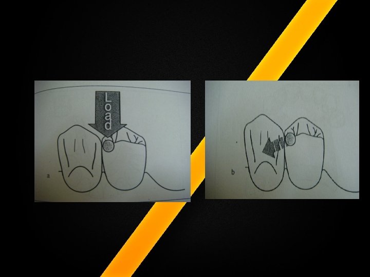
�The rest, located on the mesial occlusal surface of the abutment tooth, acts as the point of occlusion and exerts a mesial force on the tooth rather than a distal displacing force. �Pressure exerted on the extension base moves the proximal plate tissueward without torquing the tooth. �The I bar also moves mesiogingivally away from the tooth under masticatory load

�In contrast with the Kratochvil’s basic design, which necessitates heavy preparation, Krol developed a modification that avoids tooth preparation.

�KROL’S SYSTEM �This concept was introduced in 1973. �The state emphasis in Krol’s system is stress control with minimal tooth coverage and minimal gingival coverage �Krol’s clasp assemply includes the three elements: Ø Ø Ø mesial rest, proximal plate and I-bar. �Each element, however, has undergone significant change to meet Krol’s criteria. . RPI (Rest, Proxim~1 Plate, I Bar) Clasp Retainer and Its Modifications Arthur J. Krol, Dental Clinics of North America - Vol. 17, No. 4, Octoher 1973

�The current concept of Krol differ from the basic design in the following aspect: 1. The rest preparation is less extensive and rests extend only into the triangular fossa and canine rest seats are often circular, concave depressions prepared in mesial marginal ridges �Mesio-occlusal rest with the minor connector placed into the mesio-lingual embrasure, but not contacting the adjacent tooth.
 The proximal plate makes the greatest departure from Kratochvil’s design: �The prepared")
� 2) The proximal plate makes the greatest departure from Kratochvil’s design: �The prepared guiding plane is 2 to 3 mm high occlusogingivally, and the proximal plate contacts only the apical 1 mm of the guiding plane. �A distal guiding plane, extending from the marginal ridge to the junction of the middle and gingival thirds of the abutment tooth, is prepared to receive a proximal plate. . RPI (Rest, Proxim~1 Plate, I Bar) Clasp Retainer and Its Modifications Arthur J. Krol, Dental Clinics of North America - Vol. 17, No. 4, Octoher 1973

�Relief is provided at the tooth-tissue junction to allow the proximal plate to disengage when loaded. �The bucco-lingual width of the guiding plane is determined by the proximal contour of the tooth. �The proximal plate, in conjunction with the minor connector supporting the rest, provides the stabilizing and reciprocal aspects of the clasp assembly

�The retentive tip contacts the tooth from the undercut to the height of contour. This area of contact along with the rest and proximal plate contact provides stabilization through encirclement.

�In RPI system: Ø Ø Ø R = Rest P = Proximal plate I = I-bar

�MESIAL REST:

�I-BAR RETAINER:

�DISTAL PROXIMAL PLATE-LONG DISTAL GUIDING PLANE THAT EXTENDS IN TO THE TOOTH TISSUE JUNCTION:

REST �Rest preparations are less extensive in the RPI system. �The mesial rest extends only into the triangular fossa, even in molar preparations, and canine rests are often circular concave depressions prepared in the mesial marginal ridge RPI (Rest, Proxim~1 Plate, I Bar) Clasp Retainer and Its Modifications Arthur J. Krol, Dental Clinics of North America - Vol. 17, No. 4, Octoher 1973
. Giles Perryer 1997")
The Lower Free End Saddle (distal extension saddle). Giles Perryer 1997

�When aesthetics permits incisal rests can be used in mandibular anteriors �And they can be used to splint the periodontally weakened teeth

Functions of Rests � 1. To direct forces along the long axis of the abutment tooth. � 2. To prevent the denture base from moving cervically and impingingival tissue. � 3. To maintain a planned clasp-tooth relationship. � 4. To prevent extrusion of abutment teeth. � 5. To provide positive reference seats in rebasing and/or impression procedures. � 6. To serve as an indirect retainer by preventing rotation of the partial denture (Class I or II RPD’s only). Removable Partial Denture Manual Robert W. Loney, DMD, MS 2011

�REASONS FOR MESIAL REST: � As the distance from the denture base to teeth increase, the associated radius also increase and the arc or rotation become linear, hence anterior placement of rest help direct the forces more vertically onto tissues of the residual ridge

PROXIMAL PLATE: �The proximal plate makes greatest departure from Kratochvil’s design. �The prepared guide plane is 2 to 3 mm high occlusogingivally and the proximal plate contacts only 1 mm of the gingival portion of the guide plane

� Relief is provided at the tooth – tissue junction to allow the proximal plate to disengage into the proximal undercut under occlusal loading. �This proximal plate, in conjunction with the minor connector supporting the rest, provides the stabilizing and reciprocal aspects of the clasp assembly.

Advantages �Improved stabilisation �Reunites and stabilizes remaining teeth with the dental arch �Retention Improves by limiting the paths of removal and insertion �Reduces food impaction between teeth and proximal plate and protects teeth tissue junction �Provides reciprocation during insertion and removal �Distribute the forces through out the arch

I – bar: �The I-bar should be located in the gingival thirds of the buccal or labial surface of the abutment in a 0. 001 inch undercut. �The whole arm should be tapered into the terminus, with no more than 2 mm of its tip contacting abutment. 2 mm

�The retentive tip contacts the tooth from the undercut to the height of contour. �This area of contact along with the rest and proximal plate contact provides stabilization through encirclement.

�The horizontal portion of the approach arm must be located at least 3 -4 mm from the gingival margin and even farther if possible.

ADVANTAGES: �Food accumulation minimized �Approach arm does not contact abutment teeth so lateral forcers are minimized. DISADVANTAGES: � Less horizontal stabilization � Less retention

�There are three basic approaches to the application of the RPI system. �The location of the rest, the design of the minor connector (proximal plate) as it relates to the guiding plane, and the location of the retentive arm are factors that influence how this clasp system functions. �All advocate the use of a rest located mesially on the primary abutment tooth adjacent to the extension base area. RPI (Rest, Proxim~1 Plate, I Bar) Clasp Retainer and Its Modifications Arthur J. Krol, Dental Clinics of North America - Vol. 17, No. 4, Octoher 1973

I approach : �This approach recommends that the guiding plane and corresponding proximal plate minor connector extend the entire length of the proximal tooth surface, with physiological tissue relief to eliminate impingement of the free gingival margin
 and corresponding proximal plate (PP) extend")
�Bar clasp assembly in which guiding plane (GP) and corresponding proximal plate (PP) extend entire length of proximal tooth surface to contact greater surface area of guide plane which directs functional forces in horizontal direction , thus tooth {teeth} are loaded more than edentulous ridge.

II approach: �This approach suggests that the guiding plane and corresponding proximal plate minor connector extend from the marginal ridge to the junction of the middle and gingival thirds of the proximal tooth surface

�Both approaches recommend that the retaining clasp arm be located in the gingival third of the buccal or labial surface of the abutment in a 0. 001 inch undercut �This decrease amount of surface area contact of proximal plate on guide plane more evenly distributes functional force between tooth and edentulous ridge

III approach: �This approach favours a proximal plate minor connector that contacts approximately 1 mm of the gingival portion of the guiding plane and retentive clasp arm located in a 0. 001 inch undercut in the gingival third of the tooth at the greatest prominence or to the mesial away from the edentulous area
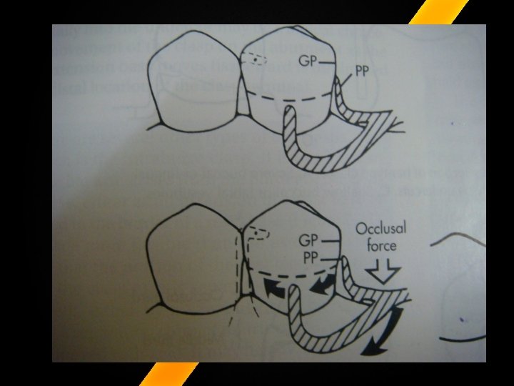

�During function, proximal plate and I-bar clasp arm are designed to move in mesiogingival direction, and disengaging tooth. �Lack of sustained contact between proximal plate and guide plane distributes more functional force to edentulous ridge. �Application of each approach is predicated on the distribution of load to be applied to the tooth and edentulous ridge. a

�The stated purpose of reducing the proximal plate is to improve gingival health by opening up embrasure spaces as much as possible.

MOUTH PREPARATION Rest Seat Preparations: � 1. For distal extension base partial dentures where a bicuspid serves as the abutment tooth Ø a mesial rest preparation is made. Ø For posterior teeth, where restorations are not placed. this rest seat can be prepared in the appropriate triangular fossa with a No. 6 carbide bur or diamond stone. Ø The marginal ridge must be lowered about 1. 5 mm and the resulting preparation must have the deepest portion in the center of the triangular fossa RPI (Rest, Proxim~1 Plate, I Bar) Clasp Retainer and Its Modifications Arthur J. Krol, Dental Clinics of North America - Vol. 17, No. 4, Octoher 1973

Ø Sufficient bulk of metal must be provided to permit the rest to function without fracturing or bending. Ø Gold requires larger and deeper preparations than the non-precious metals (chrome cobalt, nickel cobalt, etc. ). Ø This preparation should be rounded and fully polished to permit some rotation when depression of the extension base occurs.

�If a cuspid is to serve as the abutment, Ø a mesiolingual rest preparation is made. Ø The rest seat must be deep enough to prevent the metal rest from slipping gingivally. Ø As a general rule, mandibular cuspids have a thin enamel covering and when preparing an adequate rest seat, penetration into the dentin is often inevitable. Ø If dentin is exposed , the preparation should be deepened and modified to accept a gold foil, amalgam, or other restorations which can be properly contoured
 describes them as two or more vertical parallel")
Guide Planes � Mc. Cracken (2005) describes them as two or more vertical parallel surfaces of abutment teeth, so shaped to direct a prosthesis during placement and removal. � Guiding planes are used to control and limit the directions of movement of a removable partial denture as it is being inserted, removed or while it is in function.
")
Functions of guiding planes Six functions are attributed to guiding planes (Mc. Cracken 2005) � To provide one path of placement and removal �To ensure planned and intended action of the retentive and bracing components of the partial denture � To eliminate detrimental strain to the abutment teeth and the components of the framework in placing and removing the prosthesis

�To eliminate gross food traps between the abutment teeth and the denture base � To provide retentive characteristics against dislodgement of the denture when the dislodging force other than parallel to the path of removal is applied � To provide bracing characteristics against horizontal rotation of the denture

�To do this, bracing elements or proximal plates should, whenever possible, be the initial portions of the partial denture to contact the abutments. � In this way, the teeth are stabilized from the potential moving forces as retentive elements of direct retainers flex over the heights of contour into the retentive undercuts

�A guide plane is prepared on the distal surface of the abutment tooth at the occlusal one third as proposed by Pouer and associates, and should extend lingually justify enough so that the proximal plate together with the mesial minor connector will prevent lingual migration of the tooth. � The guide planes should be approximately 2 to 3 mm in height occluso-gingivally FUNDAMENTALS OF REMOVABLE PARTIAL PROSTHODONTIC DESIGN Kenneth R. Mc. Henry, D. D. S. , M. S. Terrence Mc. Lean, D. D. S.

�This guide plane will often permit the proximal plate and the mesial minor connector to contact the tooth simultaneously and provide proper reciprocation against the force exerted by the retentive buccal clasp arm during the seating and removal of the denture. �If the mesial minor connector and proximal plate cannot contact simultaneously, as may occur with cuspid abutments, then the retentive I bar should engage the mesiobuccal undercut and receive its reciprocation from the proximal plate alone

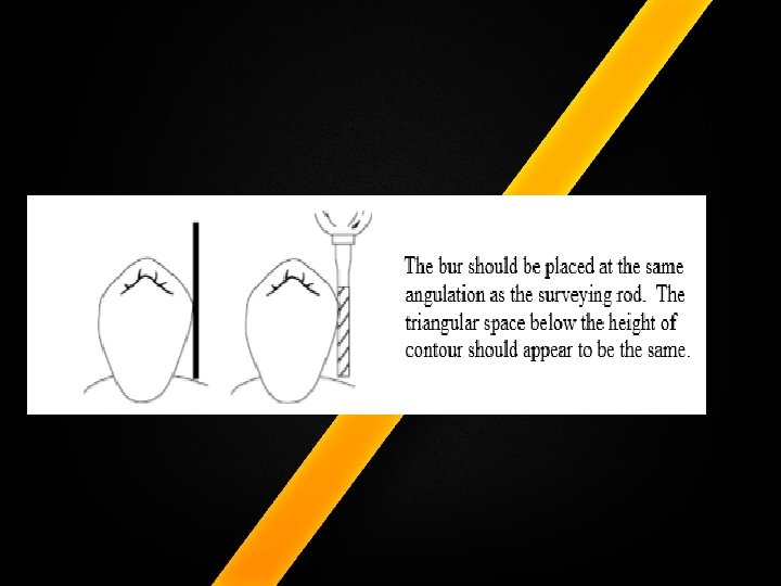
�Selection and Preparation of Guiding Planes: �a. A path of insertion is selected. �b. The number and position of guiding planes is selected. �c. With the diagnostic cast as a guide, parallel surfaces are prepared intraorally with straight cylindrical burs (#1156 or #557 L or equivalent cylindrical bur). �The surveyed cast should be nearby for comparison, so that the bur can be placed in the same relationship to the tooth as the analyzing rod makes with the diagnostic cast. � The bur should be placed at the same angulation as the surveying rod. The triangular space below the height of contour should appear to be the same Removable Partial Denture Manual Robert W. Loney, DMD, MS 2011

� d. Guiding planes should be at least 1/2 to 1/3 of the axial height of the tooth (generally a minimum of 2 mm in height). � Use a light sweeping stroke continuing to pass the bucco- and the linguo proximal line angles. � Reduction should follow the bucco-lingual curvature of the tooth, rather than slicing straight across the tooth.

�Guide planes for distal-extension cases should be slightly shorter to avoid torquing of the abutment teeth. �Lingual guiding planes for bracing or reciprocal arms should be 2 -4 mm and ideally be located in the middle third of the crown, occluso-gingivally. �Use a good finger rest to establish parallel planes.

�e. If tooth surfaces selected for guiding planes are already parallel to the path of insertion, little if any tooth modification may be necessary. � f. The prepared surfaces are polished rubber wheels or points. � g. Guiding planes are the first features prepared intraorally. If occlusal rest seats are prepared initially, placement of a proximal guiding plane will remove some of the rest seat preparation, and result in a narrowed rest with a sharp occluso-proximal angle.

�ADVANTAGES OF THE RPI CLASP � 1. Vertical masticatory force on the distal extension base causes the I bar to move mesiogingivally away from the tooth and the proximal plate to move further into the undercut of the tooth. Thus, both the I bar and the proximal plate disengage the abutment and thereby reduce torquing of the tooth. � 2. The mesial minor connector together with the proximal plate provide the necessary reciprocation and eliminate the need for a lingual arm. RPI (Rest, Proxim~1 Plate, I Bar) Clasp Retainer and Its Modifications Arthur J. Krol, Dental Clinics of North America - Vol. 17, No. 4, Octoher 1973

� 3. The mesial rest eliminates the potential "pump handle" effect that a force on the base often induces with a distal rest. � 4. The RPI clasp contacts the tooth minimally and is advantageously used on caries prone patients and since the I bar itself makes very little contact with the tooth , � 5. It is usually more esthetic than most other clasp arms

�CONTRAINDICATIONS FOR RPI CLASP �Any of the following conditions would preclude the use of the RPI clasp: �( I) Insufficient depth of vestibule to permit the approach arm of the I bar to be located at least 3 mm from gingival margin �(2) a tooth which has a severe lingual tilt and no labial or buccal undercut � (3) tissue undercut so severe that the approach arm of the I bar would be too far away from the tissue and act as a food trap or irritate the mucosa of the lip or cheek RPI (Rest, Proxim~1 Plate, I Bar) Clasp Retainer and Its Modifications Arthur J. Krol, Dental Clinics of North America - Vol. 17, No. 4, Octoher 1973
 teeth which are severely flared labially or bucally � (5) a tooth which")
�(4) teeth which are severely flared labially or bucally � (5) a tooth which has only a distobuccal retention undercut and does not require a restoration; and � (6) a mouth with a high floor in which a lingual plate is used on the lingual surface of the abutment tooth.

MODIFICATION TO RPI SYSTEM: �Krol in 1976 has given modification to RPI system. That is �RPA in which Ø Ø Ø R = rest P = proximal plate A = Akers clasp

Contraindications for a bar- type clasp q q exaggerated buccal or lingual tilts, severe tissue undercut or a shallow buccal vestibule and the desirable undercut is located in the gingival third of the tooth away from the extension base area, �this modification to RPI i. e. , RPA should be considered.

Ø Tipped abutments and tissue impingements are treated with RPA clasp. �When Akers clasp arm is used, careful attention is paid to relieve all undercuts except at the retentive tip
 Part 2. Effects of Clasp")
Analysis of Abutment Tooth Movement utilizing Mandibular Kinesiograph (MKG) Part 2. Effects of Clasp Design in Unilateral Free-end Denture Masao Moriko et al; Dental. M aterials. J ournal 8(1): 56 -64, 1989 �The Aker's clasp assembly induced the largest tooth movement. �The behaviors of the RPA clasp were generally similar to those of the Aker's. They showed a larger disto-buccal inclination of the tooth. �The RPI clasp seemed to be preferable for protecting the periodontal tissues from damage associated with larger tooth movement since it induced less inclination of the tooth in the distal direction.

A COMPARISON OF TOOTH-BORNE AND TOOTH-TISSUE- BORNE REMOVABLE PARTIAL DENTURES . Mc. Cracken , JPD , 1953, 3, 375 �Support – elastic , fibrous connective tissue covering over the residual alveolar bone , is dependent upon the quality of that support for its stability under functional stresses. �Clasp design – in tooth borne – clasp should deform sufficiently during the insertion and removal in tissue borne – flex sufficiently in the undercut to dissipate the stresses to alveolar bone

STRESS ANALYSIS IN DISTAL EXTENSION PARTIAL DENTURES . GEORGE W. HINDELS, J. Pros. Den. March, 1957 vol 7, 197 �He stated that – the masticatory stresses exerted on the base of a distal extension partial denture are transmitted to the supporting tooth through contacting parts of the appliance � Movement of the denture as a result of vertical stresses and the displaceability of the mucosa must be recognized and dealt with in tissue-borne appliances.

�Partial denture should be constructed so this movement is vertical in relation to the supporting bone �Clasps and rest should be designed to allow for this vertical movement of the denture base. �Stresses other than those vertical to the abutment teeth should be reciprocated

The effect of various clasping systems on the mobility of abutment teeth for distal-extension removable partial dentures Tebrock et al , JPD, 1979, 41, 511 � 1. 2. 3. Three clasp system Cast circumferential buccal retentive arm, a distal rest , and a lingual bracing arm Wrought wire buccal retentive arm , a distal rest , and a lingual bracing arm Buccal I-bar retentive arm , a mesial rest , and a distal plate contacting a guiding plane bracing.

� 1. 2. 3. They concluded that No difference in mobility of abutment in all three cases Any mobility increases were in a buccal direction only , or towards the flexible retentive clasp arm All five patients chose the I-bar retainer as the design of choice due to its increase resistance to dislodgement

Motion vector analysis of an abutment for a distalextension removable partial denture: A pilot study John W. Mc. Cartney, , JPD, 1980, 43, 15 � He concluded from his study that Less force to the abutment tooth was recorded when mesial rest was used as compared to a distal rest. 2. Forces transmitted to the abutment was found to be greater when the vertical load was applied to the denture base on the same side than when applied to the opposite side of the denture base. 1.

Conclusion �Requirement of a Partial denture clasp system i. e. support , stabilization, retention, reciprocation and passivity are all met by RPI system. Successful use of system requires careful analyzing of each component for function it provides and thoughtful execution of system in the abutment preparation.

Summary

References 1. MC CRACKEN’S REMOVABLE PARTIAL PROSTHODONTICS 5 th EDITION. 2. STEWART’S CLINICAL REMOVABLE PARTIAL PROSTHODONTICS 3 RD EDITION 3. INFLUENCE OF OCCLUSAL REST POSITION AND CLASP DESIGN ON MOVEMENT OF ABUTMENT TEETH. . FRANK J. KRATOCHVIL; J. Pros. Den. Jan. . Feb. , 1963 Volun 1 e 13 Number 1 4. RPI (Rest, Proxim~1 Plate, I Bar) Clasp Retainer and Its Modifications Arthur J. Krol, Dental Clinics of North America - Vol. 17, No. 4, Octoher 1973 5. MC CRACKEN’S REMOVABLE PARTIAL PROSTHODONTICS 12 TH EDITION 6. UNDERSTANDING PARTIAL DENTURE DESIGN BY KENNETH TYSON, ROBERT YEMM, BRENDON SCOTT 7. The effect of loading locations and direct retainers on movements of the abutment tooth and denture base of removable partial denture; mizuuchi et al; J ME D DENT SCIN; 2002, 49; 11 -18 8. The mandibular first premolar as an abutment for distal-extension removable partial dentures: a modified clasp assembly design Shifman et al; BRITISH DENTAL JOURNAL, VOLUME 188, NO. 5, MARCH 11 2000

9. Clasp design for distal. Osker sykora et al; QTD, 1995 212 -217 10. The Lower Free End Saddle (distal extension saddle). Giles Perryer 1997 11. Aesthetic clasp design for removable partial denture: a literature review; SADJ June 2005 ; vol 60, n 0 5, 190 -194 12. Clasp design. Davenport et al; BRITISH DENTAL JOURNAL, VOLUME 190, NO. 2, JANUARY 27 2001 13. Removable Partial Denture Manual Robert W. Loney, DMD, MS 2011 14. FUNDAMENTALS OF REMOVABLE PARTIAL PROSTHODONTIC DESIGN Kenneth R. Mc. Henry, D. D. S. , M. S. Terrence Mc. Lean, D. D. S. 15. A COMPARISON OF TOOTH-BORNE AND TOOTH-TISSUE- BORNE REMOVABLE PARTIAL DENTURES . WILLIAM L. MCCRACKEN, J. Pros. Den. May, 1953 ; Volume 3 Number 3 16. STRESS ANALYSIS IN DISTAL EXTENSION PARTIAL DENTURES. GEORGE W. HINDELS, J. Pros. Den. March, 1957 vol 7, 197 17. CONDITIONS WHICH MAY INFLUENCE THE CHOICE OF PARTIAL OR COMPLETE DENTURE SERVICE. OLIVER C. APPLEGATE, J. Pros. Den. &larch, 1957 vol 7 no 2

- Slides: 96