Routing IP Addressing Layer 2 Addressing IP Addressing


")
 네트워크와 Host Address를 구분한다. (2) Destination Host(Address)가 Local인지 Remote인지 구분한다. 서브넷마스크는")

")

 : 라우터의 Operating System이다. ROM (Read Only Memory)")

 # show version")


에 컨솔 케이블을")
#exit Router# “Ctrl +Z”도 exit와 동일하다. 한번에 중첩에서 빠져")
![최초 라우터 설정 Router#setup Continue with configuration dialog? [yes/no]: y Enter host name [Router]:](https://slidetodoc.com/presentation_image_h2/59ec394a8a997d7b6248f46313f955eb/image-32.jpg "최초 라우터 설정 Router#setup Continue with configuration dialog? [yes/no]: y Enter host name [Router]:")


 Router# copy tftp running-config Host or network configuration file")


#config-register 0 x 0 (ROM Monitor Mode) router(config)#config-register 0 x")

![라우터 초기화 하기 Router 01#erase startup-config Building configuration. . . [OK] Router 01#reload Proceed](https://slidetodoc.com/presentation_image_h2/59ec394a8a997d7b6248f46313f955eb/image-40.jpg "라우터 초기화 하기 Router 01#erase startup-config Building configuration. . . [OK] Router 01#reload Proceed")


")


 192. 168. 3. 0 E 0 192. 168. 1. 0 Router")


#router")
#router")


 IGP(Interior Gateway Protocol)의 하나이다. 동일 AS(Autonomous System) 내 동일 Area단위로")
 Routing Table을 구성한다. 대역폭을")
,")


")
 Cisco Router에 직접 연결된 Cisco Router의 정보를 볼 수 있게")


#access-list 12 permit 192. 89. 55. 0 0. 0. 0.")


, Local Subnet Broadcast, Remote Subnet Broadcast등이")

")


")


#ip route 192. 168. 100. 0 255. 0 ethernet 0")

 -")
 ISDN, PSTN을 사용한다. 라우터의 ISDN Port, Aux Port, Serial Port를")
 실제로는")


 Overview The Point-to-Point Protocol (PPP) is generally viewed as the successor")


#int serial 0 Router 02(config-if)#ip address 192. 168.")


 SVCs are temporary connections used for sporadic data transfers. They")
 can be multiplexed onto a")
#int s 1 Router(config-if)#encapsulation x 25 (Router를 DCE로 사용하는 경우는# encap")


 # show version")
")
 외부와 연결되는 라우터 내부에서는 비공인 IP Address 또는 Private IP Address를")


 – routing protocols in an")
- Slides: 157
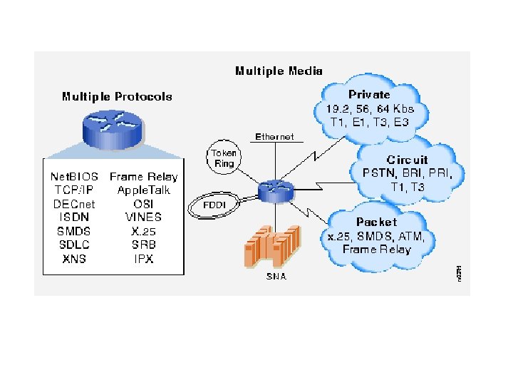
Routing
IP Addressing
Layer 2 Addressing
IP Addressing
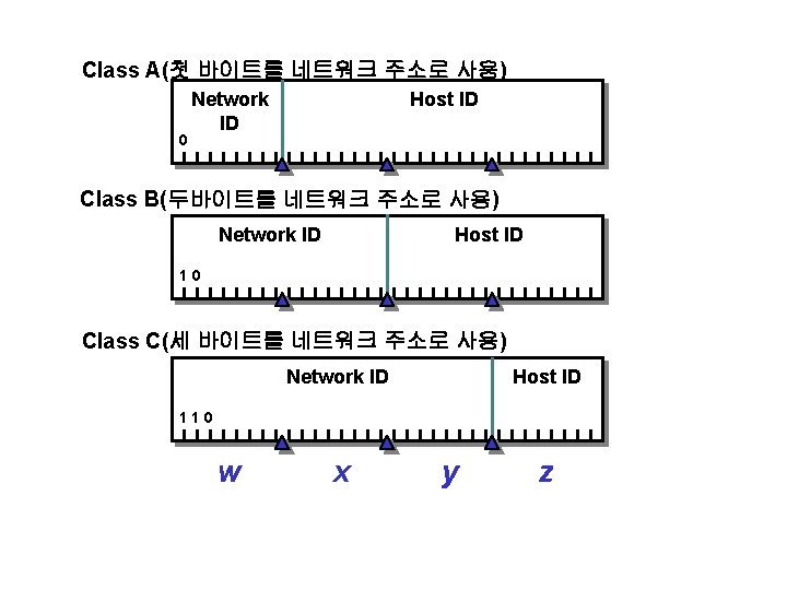
8 Bits 1 1 1 1 128 64 32 16 8 4 2 1 255 Decimal Value 32 Bits Class B Network ID Example: Host ID w. x. y. z. 131. 107. 3. 24
Number of Networks Number of Hosts per Network Range of Network IDs (First Octet) Class A 126 16, 777, 214 1 -126 Class B 16, 384 65, 534 128 -191 Class C 2, 097, 152 254 192 -223 Class A : 0으로 시작하는 1 st Octet = Network Address (1 -126, 127 Loopback, 0제외) Class B : 10으로 시작하는 2개의 Octet = Network Address (128. 0. 0. 0 - 191. 255. 0. 0) Class C : 110으로 시작하는 3개의 Octet = Network Address (192. 0. 0. 0 - 223. 255. 0) Class D : 1110으로 시작하는 4개의 Octet = Specific Multicast Group (224 -239) Class E : 1111로 시작하는 Address = Reserved (240 -255, 255 제외) 참고. 한 네트워크 상에서 호스트수 산정시 첫번째 Address는 네트워크를 나타내는 어드 레스이며, 마지막 어드레스는 브로드캐스트로 쓰인다. 따라서 “조합수 -2”가 필요하다.
Subnet Mask (1) 네트워크와 Host Address를 구분한다. (2) Destination Host(Address)가 Local인지 Remote인지 구분한다. 서브넷마스크는 IP Address 처럼 Dotted Decimal Fromat으로 표시되는데 2진수로 환산했을 때, 1은 Network Portion을, 0은 Host Portion을 의미한다. Default Subnet Mask Address Dotted Decimal Bits Used for Subnet Mask Class Notation Class A 1111 00000000 255. 0. 0. 0 Class B 11111111 00000000 255. 0. 0 Class C 11111111 0000 255. 0 Class B Example IP Address Subnet Mask Network ID Host ID 131. 107. 16. 200 255. 0. 0 131. 107. y. z w. x. 16. 200
공인 Private Address 10. 0 /8 (10. 0. 0. 1 - 10. 255. 254) 172. 16. 0. 0 / 12 (172. 16. 0. 1 - 172. 31. 255. 254) 192. 168. 0. 0 / 16 (192. 168. 0. 1 - 192. 168. 255. 254)
Router Configuration
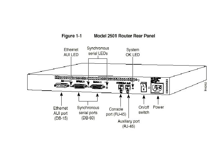
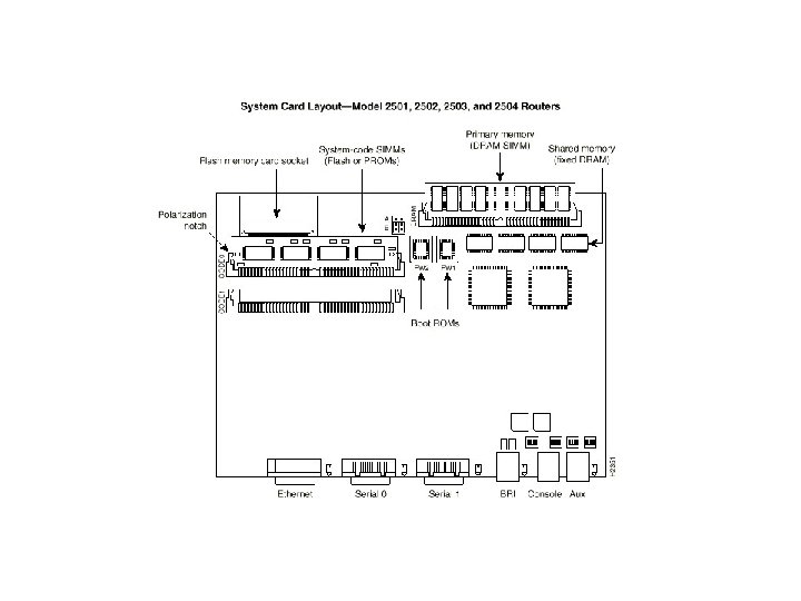
시스코 라우터의 구성 IOS(Internetworking Operating System) : 라우터의 Operating System이다. ROM (Read Only Memory) : Cisco 2500, 4000, 4500은 IOS의 Subset을 갖고 있다. Cisco 7000, 7500은 IOS를 ROM에 보유한다. ROM Chip교환으로 IOS 교체가 가능하다. Flash Memory (Erasable, Programmable Read-Onle Memory) : Cisco 2500 시리즈는 플래쉬 메모리에 IOS를 갖고 있다. IOS Update가 가능하다. NVRAM(Non. Volatile Memory) : 라우터 설정파일을 갖고 있다. RAM(Random Access Memory) - Main Memory : 작동중 IOS, Router Configuration File, ARP Cache를 보유한다. - Shared Memory : 패킷을 임시로 저장하는 Buffer로 사용한다. Interface : 네트워크를 연결하는 Ethernet, Serial Port로 각각 하나의 IP Address가 할당되어야 한다. 라우터에 따라, Ethernet, Token. Ring, FDDI, Serial, ISDN BRI, ATM Interface등을 제공한다. Console Port : Console Cable로 Terminal에 연결하여 라우터를 설정할 수 있다. Auxiliary Port : Modem연결등을 통하여 라우터를 설정할 수 있다.
Routrer Mode Exec Mode : Command를 입력할 수 있는 Mode이다. User Exec Mode Non-Destructive Command, Basic Test, System Information을 볼 수 있다. > Prompt Previleged Exec Mode configure Command, Debug Command를 사용할 수 있다. # Prompt > enable (enter)로 들어간다. ROM Monitor Mode Boot Image를 못 찾는 경우, 또는 Break Key를 사용한 경우에 나타난다. Setup Mode Configuration File이 없는 경우, 자동으로 나타나 Interractive한 라우터 설정을 가능하게 한다. #setup 명령을 통해서도 가능하다. RXBoot Mode Flash Memory에서 Boot Image를 못 찾는 경우, Router<boot>형태의 Prompt로 나타난다. Global Configuration Mode Configure Mode이다. (config)# Prompt exit, Ctrl+Z으로 빠져 나온다.
참고 : Cisco 2500, 4000 라우터 Enable Security Password 복구하기 (1) # show version 확인하여 (일반 Mode에서도 명령 가능하다. ) Configuration register is 0 x 2102 를 기록한다. (2) Router Power Down (3) Router Power ON (4) Break Command (ROM Monitor Mode로 들어간다. ) (5) > o/r 0 x 42 를 입력한다. ( 0 x 42는 Flash Memory에서 Boot, 0 x 41은 Boot ROM에서 Boot 한다. 0 x 41의 경우는 설정화일을 지우거나 보는 것만 가능하고 Password 변경은 안된다. ) (6) > i ( Initialization, Rebooting 한다. ) (7) Initial Configuration dialog? No (8) > enable 하면 # Prompt로 바로 들어 갈 수 있다. (9) # copy startup-configuration running-configuration (10) Password 변경 저장 Router 02#config term Router 02(config)#enable secret korea Router 02#copy running startup (11) Router 02#config term Router 02(config)# config-reg 0 x 2102 Router 02# reload Save ? Yes reload ? <Enter> (12) # show version으로 Register 값 확인
Password 설정 enable secret Password 바꾸기 Router 02#config term Enter configuration commands, one per line. End with CNTL/Z. Router 02(config)#enable secret korea Router 02(config)#^Z Line Console Password 설정 router#config term Enter configuration commands, one per line. End with CNTL/Z. router(config)#line console 0 router(config-line)#password router(config-line)#^Z Virtual Terminal Password 바꾸기 Router 02#config term Enter configuration commands, one per line. End with CNTL/Z. Router 02(config)#line vty 0 4 Router 02(config-line)#password newpass Router 02(config-line)#^Z
모든 Password Encryption 하기 router#config term Enter configuration commands, one per line. End with CNTL/Z. router(config)#service password-encryption router(config)#^Z router#sh runn version 11. 2 service password-encryption enable password 7 03145 A 1815182 E 5 E 4 A line con 0 password 7 01030717481 C 091 D 25 line aux 0 password 7 01030717481 C 091 D 25 line vty 0 4 password 7 01030717481 C 091 D 25
Logging in to the Router Automatically Exec Mode >logout The Default Interval the Router waits for input is 10 Minutes # no exec-timeout = # exec-timeout 0 0 >enable #exit (or logout) Context-Sensitive Help Router#con? configure connect Router#config t? terminal Enhanced Editing Command Ctrl+A, E, B, F Esc+B, F Command History #show history Ctrl+P, N
Router Status Show Version RAM NVRAM Flash Internetwork Operating System Programs Show Processes show protocols Dynamic Configuration Information Show running-config Backup(Startup) Configuration File Routing Tables and Buffers Operating System Inter. Faces Show startup-config Show mem show ip route 기타 : #show buffer (Buffer 상황표시), #show arp (Arp Cache 표시) Show flash Show interfaces
Cisco Router Console에 연결하기 1. 라우터 뒷면의 컨솔 포트(RJ 45 Port 이다)에 컨솔 케이블을 연결한다. 2. 컨솔 케이블을 터미널(통상 Notebook 또는 PC)의 Serial Port(Com 1, Com 2)에 연결한다. 3. Comport 설정을 한다. ( Baud Rate 9, 600, Data Bit 8, Parity Bit No, Stop Bit 2) 4. PC 또는 Notebook에서 Hyper. Terminal등 Emulator S/W를 작동시킨다. 5. 라우터에 전원을 넣는다. 6. 부팅화면이 보인다. 부팅이 끝나면 <Enter> Key를 친다. User EXEC 레벨에서 특권 EXEC 레벨로 들어가기 User EXEC 레벨에서는 제한된 명령만 수행된다. Router>enable Password: Router# 라우터 설정 모드로 들어가기 Router#config terminal Enter configuration commands, one per line. End with CNTL/Z. Router(config)#
라우터 설정 모드에서 빠져 나오기 Router(config)#exit Router# “Ctrl +Z”도 exit와 동일하다. 한번에 중첩에서 빠져 나올 수 있다. Help Router#? Exec commands: access-enable Create a temporary Access-List entry access-template Create a temporary Access-List entry bfe For manual emergency modes setting clear Reset functions clock Manage the system clock configure Enter configuration mode connect Open a terminal connection copy Copy configuration or image data debug Debugging functions (see also 'undebug') disable Turn off privileged commands disconnect Disconnect an existing network connection enable Turn on privileged commands erase Erase flash or configuration memory exit Exit from the EXEC
최초 라우터 설정 Router#setup Continue with configuration dialog? [yes/no]: y Enter host name [Router]: Router 01 Enter enable secret [<Use current secret>]: sk <= Enable Password 대신 사용한다. Enter enable password [password]: telecom <= Enable Secret이 설정된 경우 무의미하다. Enter virtual terminal password [password]: password <= Telnet 등으로 접속시 Password이다. Configure SNMP Network Management? [yes]: y Community string [public]: public 2 Configure IP? [yes]: y Configure IGRP routing? [yes]: n Configure RIP routing? [no]: y Configuring interface Ethernet 0: Is this interface in use? [yes]: y Configure IP on this interface? [yes]: y IP address for this interface [128. 1. 51. 254]: 128. 1. 51. 254 Number of bits in subnet field [0]: 8 Class B network is 128. 1. 0. 0, 8 subnet bits; mask is /24 Configuring interface Serial 0: Is this interface in use? [no]: n Configuring interface Serial 1: Is this interface in use? [no]: n Use this configuration? [yes/no]: y Building configuration. . . [OK] Use the enabled mode 'configure' command to modify this configuration. Router 01#
라우터 설정 보기 Router 01#show running-config <= 현재 설정 보기 Router 01#show startup-config <= 부팅시 설정 보기 Router 01#show running-config Building configuration. . . Current configuration: ! version 11. 2 service udp-small-servers service tcp-small-servers ! hostname Router 01 ! enable secret 5 $1$Ose 4$. vc. Nj. T 7 Hp. L 3 Jv. PV 441 J 6 k/ enable password telecom (enable secret이 설정되지 않았을 때 사용된다. ) ! ! interface Ethernet 0 ip address 128. 1. 51. 254 255. 0 ! interface Serial 0 no ip address shutdown !
interface Serial 1 no ip address shutdown ! router rip network 128. 1. 0. 0 ! router igrp 1 network 128. 1. 0. 0 ! no ip classless snmp-server community public 2 RO ! line con 0 line aux 0 line vty 0 4 password login ! end Router 01#
Loading Configuration File (TFTP Server) Router# copy tftp running-config Host or network configuration file [host]? Address of remote host [255. 255]? 150. 21. 32. 254 Name of Configuration File? Rcfg 1 Configure Using rcfg 1 from 150. 21. 32. 254? Y Booting rcfg 1 from 150. 21. 32. 254: !! [OK-874/1600 bytes] #copy tftp startup-config #copy running-config tftp
System Startup Overview 1. POST 2. IOS Image를 결정하기 위해 Configuration Register를 NVRAM의 Configuration File에서 찾는다. 3. Configuration File이 없으면 Setup Mode로 들어간다. 4. Configuration에 특별한 설정이 없으면 통상 Flash Memory의 Boot Image를 사용한다. 5. 설정이 있는 경우, 설정에 따른 Boot Image로 Boot한다. 6. IOS Image를 못찾는 경우, ROM Monitor Mode로 Boot 한다. 7. Flash Memory에서 Boot Image를 찾게 되었으나 못 찾는 경우, RXBoot Mode로 Boot한다.
Locating Cisco IOS Software Configuration Register Boot Field가 IOS 및 Router Configuration을 가져올 위치를 결정한다. router#sh version Configuration register is 0 x 2102 <= 0 x 2는 NVRAM의 설정을 참조한다는 의미이며, 102는 라우터별로 상이한 번호이다. 기본적으로 플래쉬 메모리에서 IOS Image를 로딩한다. # Boot System 명령으로 순서를 명시할 수 있다. router#config term Enter configuration commands, one per line. End with CNTL/Z. router(config)#boot system flash 80135403. bin router(config)#boot system tftp 80135403. bin 150. 21. 32. 254 router(config)#boot system router#sh flash System flash directory: File Length Name/status 1 4106304 80135403. bin [4106368 bytes used, 87936 available, 4194304 total] 4096 K bytes of processor board System flash (Read ONLY)
Configuration - Register Value router(config)#config-register 0 x 0 (ROM Monitor Mode) router(config)#config-register 0 x 1 (Boot From ROM) router(config)#config-register 0 X 2 (Examine NVRAM for boot system command) router(config)#config-register 0 XF (Examine NVRAM for boot system command)
Creating Software Image Backup Router#copy flash tftp System flash directory: File Length Name/status 1 4106304 80135403. bin [4106368 bytes used, 87936 available, 4194304 total] Address or name of remote host [255. 255]? Source file name? Upgrading IOS Software from Network router#copy tftp flash Proceed? [confirm] System flash directory: File Length Name/status 1 4106304 80135403. bin [4106368 bytes used, 87936 available, 4194304 total] Address or name of remote host [255. 255]? Source file name? Update가 성공하면 최종 Update가 유효하고, 실패하거나 중단되면 기존 IOS Image가 유효하다.
라우터 초기화 하기 Router 01#erase startup-config Building configuration. . . [OK] Router 01#reload Proceed with reload? [confirm] y %SYS-5 -RELOAD: Reload requested System Bootstrap, Version 5. 2(8 a), RELEASE SOFTWARE Copyright (c) 1986 -1995 by cisco Systems 2500 processor with 1024 Kbytes of main memory 라우터 이름 바꾸기 Router. A#config term Enter configuration commands, one per line. End with CNTL/Z. Router. A(config)#hostname Router 02(config)# ^Z Router 02# %SYS-5 -CONFIG_I: Configured from console by console Router 02#copy running-config startup-config Building configuration. . .
Message of the Day Banner 설정 Router. A#config term Enter configuration commands, one per line. End with CNTL/Z. Router. A(config)#banner motd # Contents of Banner # Router 02(config)# ^Z Interface Description 설정 Router. A#config term Enter configuration commands, one per line. End with CNTL/Z. Router. A(config)#int e 0 Router 02(config)# description Engineering LAN, Bldg. 18
enable secret Password 바꾸기 Router 02#config term Enter configuration commands, one per line. End with CNTL/Z. Router 02(config)#enable secret korea Router 02(config)#^Z Virtual Terminal Password 바꾸기 Router 02#config term Enter configuration commands, one per line. End with CNTL/Z. Router 02(config)#line vty 0 4 Router 02(config-line)#password newpass Router 02(config-line)#^Z Routing Protocol 변경 Router 02#config term Enter configuration commands, one per line. End with CNTL/Z. Router 02(config)#no router rip Router 02(config)#router eigrp 10 Router 02(config-router)#network 128. 1. 0. 0 Router 02(config-router)#^Z
Interface IP Address 변경 Router 02#config term Enter configuration commands, one per line. End with CNTL/Z. Router 02(config)#interface ethernet 0 <= 기존 IP Address 지운다. Router 02(config-if)#no ip address Router 02(config-if)# ip address 128. 1. 51. 1 255. 0 Router 02(config-if)#^Z IP Address 추가 설정 Router 02(config)#int e 0 Router 02(config-if)#ip address 172. 16. 3. 2 255. 0 secondary Loopback Interface 설정 실제로 존재하는 Interface가 아니라 소프트웨어적인 어드레스로 , Windows NT의 경우, MS Loopback Address와 유사하다. Router 02#config terminal Enter configuration commands, one per line. End with CNTL/Z. Router 02(config)# int loopback 0 Router 02(config-if)# %LINEPROTO-5 -UPDOWN: Line protocol on Interface Loopback 0, changed state to up Router 02(config-if)# ip address 172. 16. 1. 1 255. 0
Default Route설정 Router 02#config term Enter configuration commands, one per line. End with CNTL/Z. Router 02(config)#ip default-network-number Default Gateway 설정 ip route 0. 0 serail 0 or, ip route 0. 0 210. 116. 119. 94 Default Gateway 여러 개 설정이 가능하다.
IP Host Name # ip host Host 1 128. 1. 51. 123 210. 126. 206. 123 # show hosts Name Server Configuration DNS is Enabled by Default with server address of 255. (Local Broadcast) # no ip domain-lookup으로 Disable 시킬 수 있다. (Broadcast로 찾지 않는다. ) # ip name-server 128. 1. 51. 1 (DNS Server를 6개 까지 구체적으로 설정할 수 있다. ) # ip domain-name companyx. co. kr SNMP 설정 Router 02#config term Router 02(config)#snmp-server community public 3 rw Router 02(config)#snmp-server host 168. 126. 62. 129 public 3 snmp (NMS Server 설정) Verifying Address Configuration # telnet # ping (Simple Ping and Extended Ping) # trace
Configure Serial Line Router#config term Enter configuration commands, one per line. End with CNTL/Z. Router(config)#int s 0 Router(config-if)#clock rate 64000 <= DCE로 사용시 Clock Rate를 설정한다. Router(config-if)#bandwidth 64 Router(config-if)#^Z Router#sh int s 0 Serial 0 is down, line protocol is down Hardware is HD 64570 MTU 1500 bytes, BW 56 Kbit, DLY 20000 usec, rely 255/255, load 1/255 Encapsulation HDLC, loopback not set, keepalive set (10 sec) Router#sh controller s 0 (Interface의 Hardware 설정을 본다. ) HD unit 0, idb = 0 x 906 F 8, driver structure at 0 x 94338 buffer size 1524 HD unit 0, No cable, clockrate 56000 cpb = 0 x 11, eda = 0 x 4940, cda = 0 x 4800 RX ring with 16 entries at 0 x 114800 Router#config term Router(config)#int s 0 Router(config-if)#shutdown %LINK-5 -CHANGED: Interface Serial 0, changed state to administratively down Router(config-if)#no shutdown
router#sh int s 0 Serial 0 is down, line protocol is down Hardware is HD 64570 MTU 1500 bytes, BW 1544 Kbit, DLY 20000 usec, rely 255/255, load 1/255 Encapsulation HDLC, loopback not set, keepalive set (10 sec) Hardware Layer(Layer 1) Carrier Detect Signal을 반영한다. Datalink Layer(Layer 2) Link Beat Detection을 반영한다.
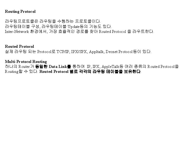
Routing Protocol
Stub Network and Static Routing Stub Network Static Route 사용 및 Default Route 설정을 하여 Dynamic Routing Over. Head를 줄인다.
Stub Network and Static Routing 적용 사례 Current configuration: version 11. 2 no service password-encryption service udp-small-servers service tcp-small-servers hostname Router 1 enable secret 5 $1$4 o. SM$A 9 KN 76 Hjz. UM 0 Ho. IBt. BDNJ 0 enable password router ip subnet-zero interface Ethernet 0 ip address 203. 227. 110. 126 255. 128 interface Serial 0 description ###Router 1### ip address 210. 116. 118. 94 255. 252 전용선 연결을 HDLC 대신 PPP를 사용 encapsulation ppp bandwidth 256 no ip classless Dynamic Route대신 Default-Gateway를 사용 ip route 0. 0 Serial 0 snmp-server community public RO default-value exec-character-bits 8 line con 0 line vty 0 4 password router end
ip subnet-zero Interface Address에 Subnet 0의 사용을 가능하게 한다. Routing Table Update의 경우에도 Subnet 0의 사용을 가능하게 한다. no ip subnet-zero가 Default 값이다. ip classes Default Route가 설정되지 않은 상태에서 라우터가 경로가 나오지 않는 Subnet의 Address를 받은 경우, Supernetting 하여 Packet을 해당 루트로 보내라는 명령이다. default-value exec-character-bits 8 exec 모드에서 사용하는 Character Set을 8 bit ASCII로 사용한다는 명령이다. service udp-small-servers 네트워크 호스트 상의 Minor한 TCP/IP서비스를 사용하기위한 명령이다. service tcp-small-servers 네트워크 호스트 상의 Minor한 TCP/IP서비스를 사용하기위한 명령이다.
Default Route Destination Network에 대한 Entry가 Routing Table에 없는 경우 Packet을 넘겨 주는 경로이다. Default Router 설정 Router 02#config term Enter configuration commands, one per line. End with CNTL/Z. Router 02(config)#ip default-network-number Default Gateway 설정도 동일한 역할을 한다. Router 02#config term Router 02(config)#ip route 0. 0 203. 255. 246. 33
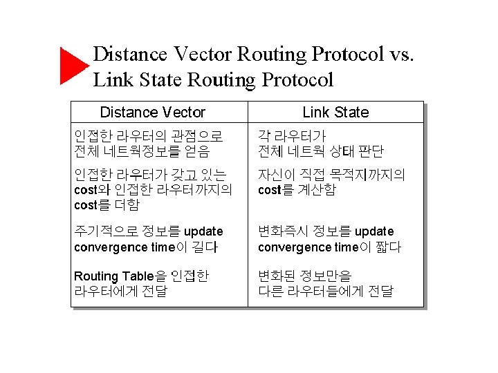
Distance Vector and RIP(Routing Information Protocol)
Router가 Booting되면 라우터는 기본적으로 자신의 Interface에 연결된 네트워크만을 라우팅테이블에 보유한다. 이에 더하여 라우터는 다음 세가지의 방법으로 라우팅 테이블을 구성한다. - Static Routes - Default Routes - Dynamic Routes # no ip routing 명령으로 IP Routing 기능을 Disable 시킬 수 있다. 이 경우, Router가 아닌 일반 Host로서 작동한다. # ip routing으로 Enable 시킨다. (Default는 Enable이다. ) Default Route설정 Router 02#config term Enter configuration commands, one per line. End with CNTL/Z. Router 02(config)#ip default-network-number
Static Route 설정 192. 168. 3. 0 E 0 192. 168. 1. 0 Router A E 0 S 0 Router B S 1 192. 168. 4. 0 192. 168. 2. 0 S 0 Router C E 0 Router A, B, C에서 각각 모든 네트워크에 대한 경로를 잡아 주어야 한다. Router A에서의 설정 Router. A# config term Router. A# ip route 192. 168. 3. 0 255. 0 serial 0 (192. 168. 2. 2도 가능하다. ) Router. A# ip route 192. 168. 4. 0 255. 0 serial 0 Router. A# ip route 192. 168. 5. 0 255. 0 serial 0 Router B에서의 설정 Router. B# config term Router. B# ip route 192. 168. 1. 0 255. 0 serial 0 Router. B# ip route 192. 168. 5. 0 255. 0 serial 1 Router c에서의 설정 Router. C# config term Router. C# ip route 192. 168. 1. 0 255. 0 serial 0 Router. C# ip route 192. 168. 2. 0 255. 0 serial 0 Router. C# ip route 192. 168. 3. 0 255. 0 serial 0 192. 168. 5. 0
Dynamic Routing 설정(RIP) 192. 168. 3. 0 E 0 192. 168. 1. 0 Router A E 0 S 0 Router B S 1 192. 168. 4. 0 192. 168. 2. 0 S 0 Router A에서의 설정 Router. A# config term Router. A(config)# router rip Router. A(config)# network 192. 168. 1. 0 Router. A(config)# network 192. 168. 2. 0 Router. A(config)# ^Z Router B에서의 설정 Router. B# config term Router. B(config)# router rip Router. B(config)# network 192. 168. 2. 0 Router. B(config)# network 192. 168. 3. 0 Router. B(config)# network 192. 168. 4. 0 Router. B(config)# ^Z S 0 Router C E 0 192. 168. 5. 0 Router C에서의 설정 Router. C# config term Router. C(config)# router rip Router. C(config)# network 192. 168. 4. 0 Router. C(config)# network 192. 168. 5. 0 Router. C(config)# ^Z
RIP Router 설정 Router 02#config term Enter configuration commands, one per line. End with CNTL/Z. Router 02(config)#router rip Router 02(config-router)#network 172. 16. 1. 0 Router 02(config-router)#network 172. 16. 2. 0 Router 02(config-router)#^Z router rip network 172. 16. 0. 0 <= 설정 후 show running-config 결과 (RIP Version 1 에서는 특별히 서브넷 마스크 정보를 넘기지 않는다. )
Router 02#sh ip route Codes: C - connected, S - static, I - IGRP, R - RIP, M - mobile, B - BGP D - EIGRP, EX - EIGRP external, O - OSPF, IA - OSPF inter area N 1 - OSPF NSSA external type 1, N 2 - OSPF NSSA external type 2 E 1 - OSPF external type 1, E 2 - OSPF external type 2, E - EGP i - IS-IS, L 1 - IS-IS level-1, L 2 - IS-IS level-2, * - candidate default U - per-user static route, o - ODR Gateway of last resort is not set 172. 16. 0. 0/24 is subnetted, 2 subnets C 172. 16. 1. 0 is directly connected, Loopback 0 C 172. 16. 2. 0 is directly connected, Loopback 1 C 172. 16. 3. 0 is directly connected, Ethernet 0 > debug ip rip 명령은 RIP Routing Update 상황을 Display 해 준다. # no debug ip rip로 Turn-Off 한다.
Router#sh ip protocol Routing Protocol is "rip" Sending updates every 30 seconds, next due in 9 seconds Invalid after 180 seconds, hold down 180, flushed after 240 Outgoing update filter list for all interfaces is not set Incoming update filter list for all interfaces is not set Redistributing: rip Default version control: send version 1, receive any version Routing for Networks: 150. 21. 0. 0 Routing Information Sources: Gateway Distance Last Update Distance: (default is 120) Routing Protocol is "ospf 10” Sending updates every 0 seconds Invalid after 0 seconds, hold down 0, flushed after 0 Outgoing update filter list for all interfaces is not set Incoming update filter list for all interfaces is not set Redistributing: ospf 10 Routing for Networks: 150. 21. 0. 0 Routing Information Sources: Gateway Distance Last Update Distance: (default is 110)
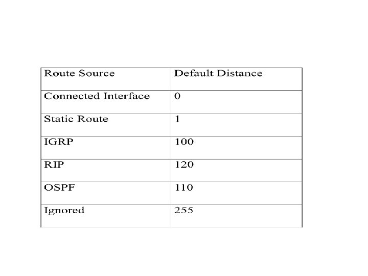
Distance 예를 들어 RIP와 OSPF를 동시에 사용하는 라우터의 경우, 경로 설정시 OSPF의 경로가 우선적으로 결정되는데 이는 OSPF의 Distance 값은 110이 Default이고, RIP는 120이기 때문이다. Distance 명령을 사용하여 바꿀 수 있다. Router 02#config term Enter configuration commands, one per line. End with CNTL/Z. Router 02(config)#router rip Router 02(config-router)#distance 100 Router 02(config-router)#^Z <= RIP 모든 루트(Route)에 대해서 Distance를 100으로 바꾸었다. 특정 네트워크의 Distance를 바꾸려면 distance 명령과, access-list 명령을 같이 사용한다. Router 02(config)#router rip Router 02(config-router)#distance 130 172. 16. 1. 0 0. 0. 0. 255 1 Router 02(config-router)#access-list 1 permit 172. 16. 1. 0 0. 0. 0. 255 Router 02(config)#^Z <= Access-List를 사용하여, 특정 네트워크 172. 16. 1. 0 의 Distance 값을 130으로 바꾸었다.
Distribute-list Incoming, or Outgoing RIP Update 루트를 삭제한다. Distribute-list와 access-list를 사용한다. Router 02#config term Enter configuration commands, one per line. End with CNTL/Z. Router 02(config)#router rip Router 02(config-router)#distribute-list 1 in Router 02(config-router)#^Z Router 02# %SYS-5 -CONFIG_I: Configured from console by console Router 02#config term Enter configuration commands, one per line. End with CNTL/Z. Router 02(config)#access-list 1 deny 172. 16. 4. 0 0. 0. 0. 255 Router 02(config)#access-list 1 permit any Router 02(config)#^Z <= Router 02에 루트를 Update 하는 네트워크 중 172. 16. 4. 0 네트워크로부터의 루트 Update만을 못하게 하고 나머지 네트워크로 부터의 루트 Update는 하게 한다.
Router 02#config term Enter configuration commands, one per line. End with CNTL/Z. Router 02(config)#router rip Router 02(config-router)#distribute-list 1 in ethernet 0 Router 02(config-router)#^Z Router 02# %SYS-5 -CONFIG_I: Configured from console by console Router 02#config term Enter configuration commands, one per line. End with CNTL/Z. Router 02(config)#access-list 1 deny 172. 16. 4. 0 0. 0. 0. 255 Router 02(config)#access-list 1 permit any Router 02(config)#^Z <= Router 02에 루트를 Update 하는 네트워크 중 172. 16. 4. 0 네트워크로부터의 루트 Update만을 못하게 하고 나머지 네트워크로 부터의 루트 Update는 하게 하는데, Ethernet Interface를 명시해서 하는 경우
Router 02#config term Enter configuration commands, one per line. End with CNTL/Z. Router 02(config)#router rip Router 02(config-router)#distribute-list 1 out Router 02(config-router)#^Z Router 02# %SYS-5 -CONFIG_I: Configured from console by console Router 02#config term Enter configuration commands, one per line. End with CNTL/Z. Router 02(config)#access-list 1 deny 172. 16. 1. 0 0. 0. 0. 255 Router 02(config)#access-list 1 permit any Router 02(config)#^Z <= Router 02가 루트를 Update 하는 네트워크 중 172. 16. 1. 0 네트워크로부터의 루트 Update만을 못나가게 하고, 나머지 네트워크의 업데이트는 허용하는 경우
Passive Interface를 해당 Interface에 적용 시키면 해당 Interface는 다른 라우터에 Update를 하지 않는다. Router 02#config term Enter configuration commands, one per line. End with CNTL/Z. Router 02(config)#router rip Router 02(config-router)#passive-interface ethernet 0 Router 02(config-router)#^Z
Link State and OSPF
OSPF(Open Short Path First) IGP(Interior Gateway Protocol)의 하나이다. 동일 AS(Autonomous System) 내 동일 Area단위로 라우팅이 이루어진다. Link State Routing Algorythm을 사용한다.
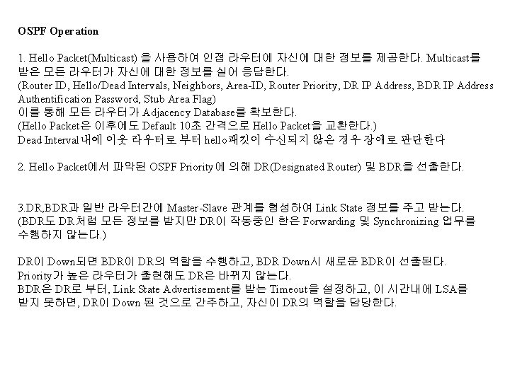
4. 각 라우터는 Link State Database를 가지고, SPF(Short Path First) Routing Table을 구성한다. 대역폭을 기준으로 Short Path를 구성한다. 즉 최고의 경로를 산정한다. 5. Link State에 변화가 생기는 경우, 각 라우터는 224. 0. 0. 6(to OSPF DR and BDR)으로 LSU(Link State Update) Packet을 보낸다. 여기에는 LSA(Link State Advertisement) Entry가 들어 있다. DR은 LSAck Packet을 해당 라우터에 보낸 후 224. 0. 0. 5(to all OSPF Routers) 으로 LSU를 Flooding 한다. 각 라우터는 LSAck로 응답한다. 각 라우터는 매 30분 간격으로 Link State Update Packet을 발생시켜 라우팅테이블을 Update한다.
OSPF의 장점 빠른 Convergence가 가능하다. OSPF는 사용 가능한 모든 경로에 Load Balancing한다. OSPF는 VLSM(Subnetting), CIDR(Class Inter-Domain Routing, Supernetting)을 지원한다. 멀티캐스트의 사용으로 네트워크 트래픽에 유리하다. OSPF에서의 Cost 값 산정 cost = 10000(10 EXP 8) / Bandwidth in bps 10 M ethernet = 10 EXP 8 / 10 EXP 7 = 10 E 1 라인 = 10 EXP 8 / 2048000 = 49 (10 M Ethernet에 비해 높은 코스트를 갖는다. ) 임의로 수정해 줄 수도 있다. CIDR(Class Interdomain Routing) 서브네팅 진행 되면서 라우팅 테이블이 증가하게 된다. CIDR은 이러한 인터넷 라우팅 테이블의 폭증을 막는 방법으로 Supernetting이라고도 한다. CIDR은 복수의 라우팅 테이블을 보다 작은 수로 집약한다. route summarization Consolidation of advertised addresses in OSPF and IS-IS. In OSPF, this causes a single summary route to be advertised to other areas by an area border router. It Uses Common Subnetbits to summarize routes.
Area 네트워크가 증가하면 각 라우터의 Link State Datebase가 커지고 Short Path Tree 계산에도 시간이 걸리는등 네트워크 퍼포먼스가 떨어지므로 Area라는 제한된 영역으로 라우팅 영역을 분할 하게 된다. 하나의 AS(Autonomous System)는 여러 개의 Area로 나누어 질 수 있다. OSPF Area가 하나 이상일 경우 반드시 area 0라는 Backbone Area를 갖어야 한다. 나머지 Area는 Area 0에 연결되어야 한다. Area 내의 라우터를 Internal Router라 한다. Area 간 중간에서 연결하는 라우터를 Area Border Router라 한다. Backbone Area에 간접적으로 새로운 Area에 연결되는 것을 Virtual Link라 한다. Backbone Area에 연결된 Area로 더 이상 다른 Area로 연결되지 않은 Area를 Stub Area라 한다. Autonomous system border routers (ASBRs) -- ASBRs are OSPF routers that participate in multiple autonomous systems. An ASBR can be connected to a number of OSPF autonomous systems, or to one or more OSPF autonomous systems and one or more networks running another routing protocol.
Other AS Backbone Area Stub Area Other AS ABR Virtual Link Area
OSPF Routing Hierarchy
OSPF Packet Header Format Type -- Identifies the OSPF packet type as one of the following Hello -- Establishes and maintains neighbor relationships. Database description -- Describes the contents of the topological database. These messages are exchanged when an adjacency is being initialized. Link-state request -- Requests pieces of the topological database from neighbor routers. These messages are exchanged after a router discovers (by examining database description packets) that parts of its topological database are out of date. Link-state update -- Response to a link-state request packet. These messages are also used for the regular dispersal of LSAs. Several LSAs can be included within a single link-state update packet. Link-state acknowledgment -- Acknowledges link-state update packets.
OSPF Router 설정 Back. Bone Router 02#config term Enter configuration commands, one per line. End with CNTL/Z. Router 02(config)#router ospf 10 <= 10은 AS Number이다. Router 02(config-router)#network 172. 16. 1. 0 0. 0. 0. 255 area 0 <= area 0는 Backbone Area임을 나타낸다. Router 02(config-router)#area 0 range 172. 16. 1. 0 255. 0 Router 02(config-router)#network 172. 16. 3. 0 0. 0. 0. 255 area 10 <=area 10은 Backbone Area에 area 10이 연결되고 있음을 나타낸다. Border Router 03#config term Enter configuration commands, one per line. End with CNTL/Z. Router 03(config)#router ospf 10 <= 10은 AS Number이다. Router 03(config-router)#network 172. 16. 4. 0 0. 0. 0. 255 area 10 <=area 10은 Backbone Area에 area 10이 Router 02(config-router)#area 10 range 172. 16. 4. 0 255. 0 연결되고 있음을 나타낸다.
Virtual Link Router A # router ospf 10 # area 1 virtual link 192. 168. 2. 1 Router B # router ospf 10 # area 1 virtual link 192. 168. 1. 1 Router 0 Area 0 Virtual Link Router A 192. 168. 1. 1 Backbone Router Border Router Area 1 Router B 192. 168. 2. 1 Area 2
Router interface의 Cost값을 임의 변경 하기 Router 02#config term Enter configuration commands, one per line. End with CNTL/Z. Router 02(config)#int ethernet 0 Router 02(config-if)#ip ospf cost 100 라우팅 경로를 바꾸거나, Load Balancing을 조절할 수 있다. # show ip ospf ethernet 0로 확인할 수 있다. Optional Command # ip ospf priority number (0 -255)
Verifying OSPF Operation show ip route show ip protocol show ip ospf interface show ip ospf neighbor detail show ip ospf database show ip ospf border-routers show ip ospf virtual-links debug ip ospf ? clear ip ospf ?
CDP (Cisco Discovery Protocol)
CDP (Cisco Discovery Protocol) Cisco Router에 직접 연결된 Cisco Router의 정보를 볼 수 있게 하는 프로토콜이다. Datalink Layer에서 작동한다. Physical Layer는 LAN, WAN(Frame Relay, SMDS, ATM)등을 지원한다. 상위 프로토콜(IP, IPX, Appletalk)에 상관 없이 작동한다. Cisco Router, Switch, Access Server간에도 작동한다. # show cdp neighbors details # show cdp entry Router. B 등의 명령을 사용, 인접 시스코 라우터의 정보를 볼 수 있다. # cdp timer 30 (Update Time) # cdp holdtime 90 ( CDP Packet 보유시간) 등의 명령으로 파라미터를 조정할 수 있다. router#config term router(config)#no cdp run <= 전체적으로 Disable 시킨다. router#config term router(config)#int e 0 router(config-if)#no cdp enable <= Interface별로 Disable 시킨다.
Access List
Routing and Firewalls
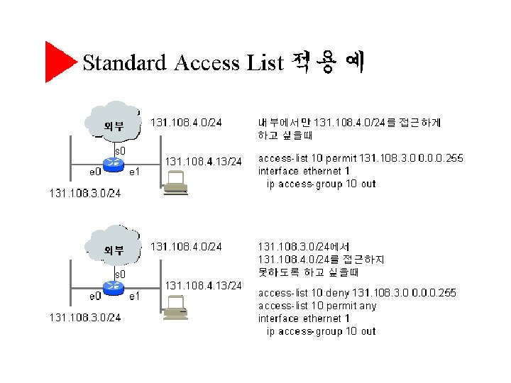
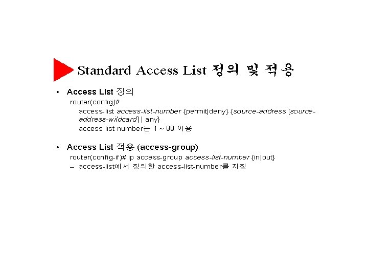
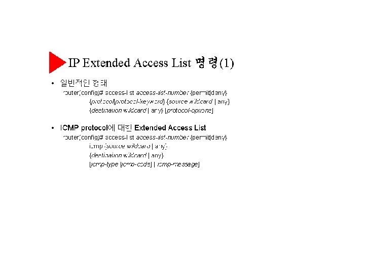
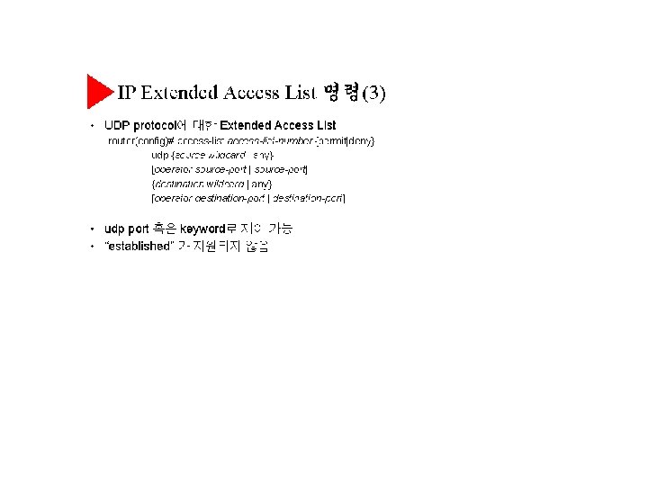
Access List IP 트래픽에 대한 필터링 기능을 수행한다. 라우터에 기본적으로 금지된 Broadcast Forwarding을 필요한 서브넷에 Enable 시켜 줄 수 있다. Standard IP Access List와 Extended IP Access List가 있다. Standard IP Access List 송신지의 IP Address만으로 Access를 통제한다. Access List 번호 1 -99번을 사용한다. Access List가 특정 Address를 Reject하는 경우, 라우터는 패킷을 버리고 “Host Unrechable” ICMP Message를 돌려준다. Extended IP Access List 송신지의 IP Address, Port Address 도착지의 IP Address, Port Address를 사용하여 Access를 통제한다. Access List 번호 100 -199를 사용한다. Helper Addressing 라우터는 기본적으로 브로드캐스트를 차단한다. Helper Service는 브로드캐스트를 목적 서버에 Direct로 Forwarding할 수 있게 한다.
Standard IP Access List 예제 2. 192. 168. 3. 0 E 0 192. 168. 1. 0 Router A E 0 S 0 Router B S 1 192. 168. 4. 0 192. 168. 2. 0 S 0 Router C E 0 192. 168. 5. 0 위 구성에서 192. 168. 3. 0 네트워크의 모든 호스트가 192. 168. 5. 0 네트워크에 Access하지 못하게 설정한다. Router C에서의 설정 Router. C# config term Router. C(config)# access-list 1 deny 192. 168. 3. 0 0. 0. 0. 255 Router. C(config)# access-list 1 permit 0. 0 255 Router. C(config)# interface serial 0 Router. C(config-if)# ip access-group 1 in Router. C(config)# ^Z 192. 168. 3. 0 0. 0. 0. 255은 192. 168. 3. 0 네트워크의 모든 호스트가 해당됨을 의미한다. Access list 설정을 하면(permit이건 deny이건) 암묵적으로 모든 패킷에 대해 deny설정을 하므로 반드시 “permit 0. 0 255”를 해주어야 한다.
Any = 0. 0 255 = any Address Wildcard Mask가 생략되면 0. 0을 의미한다.
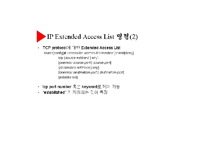
192. 168. 3. 0 Extended IP Access List 예제 1. E 0 192. 168. 1. 0 Router A E 0 S 0 Router B S 1 192. 168. 4. 0 192. 168. 2. 0 S 0 Router C E 0 192. 168. 5. 0 192. 168. 1. 0 네트워크에 있는 서버 A(192. 168. 1. 11)에 Telnet 만을 제외하고 모든 TCP Access를 막는다. 192. 168. 3. 0에서는 192. 168. 5. 0에 Access할 수 없다. 192. 168. 1. 0과 192. 168. 5. 0 네트워크는 상호 통신 가능해야 한다. Router. A# config term Router. A(config)# access-list 100 deny tcp any host 192. 168. 1. 11 eq telent Router. A(config)# access-list 100 deny ip 192. 168. 3. 0 0. 0. 0. 255 192. 168. 5. 0 0. 0. 0. 255 Router. A(config)# access-list 100 permit ip any Router. A(config)# interface serial 0 Router. A(config)# ip access-group 100 in Router. A(config)# ^Z Router. C# config term Router. C(config)# interface serial 0 Router. C(config)# ip access-group 100 in
Extended IP Access List 예제 2 128. 88. 1. 0 e 0 A e 1 128. 88. 3. 0 Router B 128. 88. 1. 2 access-list 104 permit tcp any 128. 88. 0. 0. 255 established (현재 설정된 TCP Port 허용) access-list 104 permit tcp any host 128. 1. 1. 2 eq smtp access-list 104 permit udp any eq domain any access-list 104 permit icmp any any echo-reply interface e 1 ip access-group 104 in
Access List를 어떤 Port에 적용할 것인가? Extended의 경우는 Deny하려는 Traffic의 소스에 가장 가까운 Port에 적용하며, Standard의 경우는 Deny 하려는 Traffice의 Destination에 가장 가까운 Port에 적용한다. Verifying Access List # show ip interface # show access-list # show start-config, or running-config
Virtual Terminal Aceess 제한 Router(config)#access-list 12 permit 192. 89. 55. 0 0. 0. 0. 255 Router(config)#line vty 0 4 Router(config-line)#access-class 12 in
Helper - Address
Helper - Address 144. 253. 1. 0 A e 0 144. 253. 1. 1 e 1 144. 253. 2. 0 Router 144. 253. 1. 1 144. 253. 2. 2 Boot. P Server Interface e 0 ip address 144. 253. 1. 1 255. 0 ip help-address 144. 253. 2. 2 ( Broadcast => Unicast) ( e 0에 도착하는 Subnet Broadcast를 144. 253. 2. 2로 Unicast 한다. ) Interface e 0 ip address 144. 253. 1. 1 255. 0 ip help-address 144. 253. 2. 2 ip forward-protocol udp 3000 no ip forward-protocol udp 69 (e 0에 도착하는 Broadcast를 144. 253. 2. 2로 Unicast 하는데 있어, UDP Destination Port 3000번을 쓰는 Packet은 넘기고, 69번을 쓰는 Packet은 Filtering 한다. 즉 69번을 쓰는 Packet만 Filtering된다. ) Interface e 0 ip address 144. 253. 1. 1 255. 0 ip help-address 144. 253. 2. 255 (Broadcast => Broadcast) ( e 0에 도착하는 Broadcast를 144. 253. 2. 255로 Broadcast한다. )
참고 : 라우터와 Broadcast Address에는 제한된 Broadcast(255. 255), Local Subnet Broadcast, Remote Subnet Broadcast등이 있는데 라우터의 Default 설정의 경우, Remote Subnet Broadcast만 해당 네트워크로 Forwarding된다. Helper-Address를 설정하면 제한된 Broadcast, Local Subnet Broadcast도 Forwarding 할 수 있다. 제한된 Broadcast(255. 255)는 통상 DHCP Broadcast의 경우처럼 해당 호스트의 IP Address가 설정이 안된 경우등 제한된 경우에 발생한다.
DHCP와 제한된 Broadcast DHCPDISCOVER DHCPREQUEST Source IP Address = 0. 0 Dest. IP Address = 255 Hardware Address = 08004. . . . Requested IP Address = 131. 107. 8. 13 Server Identifier = 131. 107. 3. 24 DHCPOFFER DHCPACK Source IP Address = 131. 107. 3. 24 Dest. IP Address = 255 Offered IP Address = 131. 107. 8. 13 Client Hardware Address = 08004. . . Subnet Mask = 255. 0 Length of Lease = 72 hours Server Identifier = 131. 107. 3. 24 DHCP Option: Router = 131. 107. 8. 1
IGRP(Interior Gateway Routing Protocol)
IGRP Broadcast : 90 sec Intervals로 자신의 라우팅테이블을 Broadcast한다. 새로운 Path가 Cost 값이 적으면 새로운 Route로 Update한다. 270초 안에 Route Update가 일어나지 않으면 그 Route는 Inaccessible로 선언하고, 이후 제거한다. Flash Updates : Network Topology 변경이 발견되면 Flash Updates가 일어난다. Hold Down Timer : 100 sec # no metric holddown 명령으로 Disable 시킬 수 있다. RIP가 홉수를 메트릭 값으로 사용하듯이, IGRP는 Dimensionless Cost를 메트릭 값으로 사용한다. 대역폭(Bandwidth), 지연(Delay), 신뢰성(Reliability), 부하(Loading), MTU(송수신시 패킷 사이즈) 가 Dimensionless Cost의 구성요소이다. Default로 Bandwidth와 Delay로 Cost를 결정하나, 다른 요소를 추가할 수 있다.
IGRP 설정방법 Router 02#config term Enter configuration commands, one per line. End with CNTL/Z. Router 02(config)#router igrp ? <1 -65535> Autonomous system number Router 02(config)#router igrp 100 Router 02(config-router)# network 172. 16. 1. 0 Router 02(config-router)# network 172. 16. 2. 0 Router 02(config-router)# network 172. 16. 3. 0 Router 02(config-router)#^Z Router 02#show running-config router igrp 100 network 172. 16. 0. 0 <= Default Subnetmask를 적용한 형태의 네트워크로 나타난다. 인접라우터에서 라우팅테이블을 보면 위 세개의 네트워크가 모두 나타난다.
Display IGRP Routing Information show ip route show ip protocols show ip interfaces debug ip igrp transaction debug ip igrp events
EIGRP(Enhanced IGRP)
EIGRP 설정방법 Router 02#config term Enter configuration commands, one per line. End with CNTL/Z. Router 02(config)#router eigrp ? <1 -65535> Autonomous system number Router 02(config)#router eigrp 100 Router 02(config-router)#network 172. 16. 1. 0 Router 02(config-router)#network 172. 16. 2. 0 Router 02(config-router)#network 172. 16. 3. 0 Router 02(config-router)#^Z Router 02#show running-config router eigrp 100 network 172. 16. 0. 0 (Auto Summary: Default) no auto-summary
Redistribution
RIP와 OSPF Ridistribution router ospf 10 restribute rip metric 10 network 192. 168. 48. 0 0. 0. 15. 255 area 2 router rip redistribute ospf 10 metric 1 network 192. 168. 49. 0 network 192. 168. 62. 0 network 192. 168. 65. 0
RIP 와 EIGRP Redistribution router eigrp 10 redistribute rip metric 10000 1000 255 1 1500 (B/W, Delay, Rely, Load, MTU) network 192. 168. 2. 0 network 192. 168. 3. 0 network 192. 168. 4. 0 router rip redistribute eigrp 10 metric 1 network 192. 168. 2. 0 network 192. 168. 3. 0 network 192. 168. 4. 0 rip metric 수치는 #show interface ethernet 0(Ethernet 0의 경우)로 파악할 수 있다. Router#sh int e 0 Ethernet 0 is up, line protocol is down Hardware is Lance, address is 0000. 0 c 92. 80 ed (bia 0000. 0 c 92. 80 ed) Internet address is 150. 21. 32. 252/16 MTU 1500 bytes, BW 10000 Kbit, DLY 1000 usec, rely 128/255, load 1/255 Encapsulation ARPA, loopback not set, keepalive set (10 sec) ARP type: ARPA, ARP Timeout 04: 00
Static Route Redistribution Router 02(config)#ip route 192. 168. 100. 0 255. 0 ethernet 0 등으로 Stastic Route를 을 추가한 후 Router 02(config)# router rip Router 02(config-router) redistribute static 으로 Static Route를 Redisribute하면 이후 라우터간에 Static Route도 Update된다.
WAN Service설정 - PPP & HDLC - Frame Relay - X. 25
WAN Connectivity - Dedicated Connectivity Leased Line CSU/DSU를 사용한다. 56 K/64 K(DS 0) - 115 M(OC 3)까지 지원한다. 통상 T 1(1. 544 M) /E 1(2. 048 M) / T 3(45 M)까지 사용한다. PPP or HDLC at Data Link Layer - Asynchronous Dial-in Connectivity Modem을 사용 , PSTN을 경유하여 Remote Access Server에 접속하여 LAN에 연결되는 방식이 있다. (Cisco 2511등의 경우, 115 K Async Port를 지원한다. Cisco 2501의 aux Port의 경우 38. 4 K 까지 지원한다. ) Terminal Server의 Virtual Terminal (ex. Telnet) Session으로 접속하는 방법이 있다.
- DDR(Dial-On Demand Routing) ISDN, PSTN을 사용한다. 라우터의 ISDN Port, Aux Port, Serial Port를 사용하여 연결한다. (주로 ISDN Port를 사용한다. ) Network Busy시 Load Balancing, Network Down시 Backup 경로로 많이 사용한다. SOHO Network의 연결에도 사용된다. PPP or HDLC at Data Link Layer(2 B) , LAPD(1 D) MP(Multi-Link PPP)를 지원한다. ISDN 연결 ISDN BRI의 경우 NT를 사용 연결하며, PRI의 경우 CSU를 사용한다. Cisco 2500의 경우 ISDN BRI를 지원하고(Router ISDN Port + NT + Carrier ISDN Switch ) Cisco 4000, 7000 Series의 경우 ISDN PRI를 지원한다. (ISDN PRI Port + CSU + Carrier ISDN Switch) 라우터의 일반 Serial Port를 사용하는 경우는 (Router + TA + NT순으로 연결한다. ) Cisco 1004의 경우는 ISDN 라우터로 NT를 내장하고 있으므로, 별도의 NT가 필요 없다.
- Packet Switched Network Frame Relay, X. 25, ATM, SMDS(Switched Multimegabit Data Service) 실제로는 Virtual Circuit을 사용한다. (PVC, SVC) Cisco 4, 000, 7, 000, 3600, 2600, Light. Stream 1010 ATM Switch등이 ATM 을 지원한다. Router의 Serial Port가 Frame Relay를 지원하며, DSU/CSU를 사용하여 연결할 수도 있고, 프레임릴레이 스위치에 바로 연결할 수도 있다.
Point-to-Point Protocol. A successor to SLIP, PPP provides router-to-router and host-to-network connections over synchronous and asynchronous circuits. High-Level Data Link Control. Bit-oriented synchronous data link layer protocol developed by ISO. Derived from SDLC, HDLC specifies a data encapsulation method on synchronous serial links using frame characters and checksums. Synchronous Data Link Control. SNA data link layer communications protocol.
PPP & HDLC Configuration
Point-to-Point Protocol (PPP) Overview The Point-to-Point Protocol (PPP) is generally viewed as the successor to the Serial Line IP (SLIP) protocol. PPP provides router-to-router and host-to-network connections over both synchronous and asynchronous circuits. PPP emerged in the late 1980 s in response to a lack of encapsulation protocols for the Internet that was blocking growth of serial-line access. PPP was bascially created to solve remote Internet connectivity problems. PPP supports a number of network layer protocols, including Novell IPX and DECnet. PPP Supports - Asynchronous Serail - HSSI(High Speed Serail Interface) : T 3 Serail Line - ISDN - Synchronous Serail : Leased Line
PPP Frame Formats Flag -- Indicates the beginning or end of a frame and consists of the binary sequence 01111110. Address -- Consists of the standard broadcast address, binary sequence 1111. PPP does not assign individual station addresses. Control -- 1 byte that consists of the binary sequence 00000011, which calls for transmission of user data in an unsequenced frame. A connectionless link service similar to that of Logical Link Control (LLC) Type 1 is provided. Protocol -- 2 bytes that identify the protocol encapsulated in the Information field of the frame. Data -- Zero or more bytes that contain the datagram for the protocol specified in the Protocol field. The default maximum length of the Information field is 1, 500 bytes. By prior agreement, consenting PPP implementations can use other values for the maximum Information field length. Frame Check Sequence (FCS) -- Normally 16 bits (2 bytes).
PPP 설정 WAN을 경유하는 라우터간에는 동일한 Encapsulation 방식을 사용해야 한다. ISO HDLC Protocol은 동일한 Vendor Router를 사용해야 한다. 상이한 Vendor의 라우터간에 Packet Encapsulation에 호환성을 부여하기 위한 프로토콜이 PPP(Point to Point Protocol)로 전용선 및 PSTN, ISDN 등을 지원한다. Router#config term Router(config-if)#int s 1 Router(config-if)#ip address 210. 123. 1. 1 255. 0 Router(config-if)#bandwidth 64 Router(config-if)#username Router. C password ( Remote Router 설정, password 를 동일 하게 설정해야 한다. ) Router(config-if)#encapsulation ppp Router(config-if)#ppp authentication chap (pap, chap 등을 선택할 수 있다. ) Router(config-if)#ppp chap hostname common (각 라우터의 공통 호스트 이름을 동일하게 설정 한다. ) Router(config-if)#ppp chap password (Unknown Host에 대한 인증 Password) Router(config-if)#no shutdown Verifying PPP #show interfaces s 1
Frame Relay Configuration
Basic Configurartion Router 02#config term Router 02(config)#int serial 0 Router 02(config-if)#ip address 192. 168. 3. 2 255. 0 Router 02(config-if)#encapsulation frame-relay Router 02(config-if)#frame-relay lmi-type ansi Router(config-subif)#frame-relay map ip 192. 168. 3. 1 110 broadcast Router(config-if)#bandwidth 64 Router 02(config)#router rip Router 02(config-router)#network 192. 168. 3. 0 Router 03#config term Router 03(config)#int serial 0 Router 03(config-if)#ip address 192. 168. 3. 1 255. 0 Router 03(config-if)#encapsulation frame-relay Router 03(config-if)#frame-relay lmi-type ansi Router(config-subif)#frame-relay map ip 192. 168. 3. 2 120 broadcast Router 03(config-if)#bandwidth 64 Router 02(config)#router rip Router 02(config-router)#network 192. 168. 3. 0 LMI(Link Management Interface) Protocol: 주기적으로 PVC등의 연결을 Polling하는 프로토콜로 LMI Type은 프레임릴레이 스위치 방식에 따라 결정된다. Keepalive 값은 Polling 주기 이다. 단위는 sec이다.
Multi-Point Subinterface Configuration DLCI =120 10. 17. 0. 1 /24 DLCI =110 s 1. 1 s 1. 2 s 1. 3 s 1. 1=10. 17. 0. 2/24 DLCI =130 s 1. 1=10. 17. 0. 3 /24 DLCI =140 Router#config term Router(config)#int s 1 Router(config-if)#no ip address Router(config-if)#encapsulation frame-relay Router(config-if)#int serial 1. 1 multipoint Router(config-subif)#ip address 10. 17. 0. 1 255. 0 Router(config-subif)#bandwidth 64 Router(config-subif)#frame-relay map ip 10. 17. 0. 2 120 broadcast Router 02(config)#router rip Router 02(config-router)#network 10. 0 s 1. 1=10. 17. 0. 4 /24 각 라우터 설정 int serial 1 no ip address encapsulation frame-relay int serial 1. 1 multipoint ip address 10. 17. 0. 2 255. 0 bandwidth 64 frame-relay map ip 10. 17. 0. 1 110 broadcast router rip network 10. 0
Point-to-Point Subinterface Configuration DLCI =120 10. 17. 0. 1 /24 DLCI =110 s 1. 1 s 1. 2 s 1. 3 s 1. 1=10. 17. 0. 2/24 DLCI =130 s 1. 1=10. 17. 0. 3 /24 DLCI =140 Router#config term Router(config)#int s 1 Router(config-if)#no ip address Router(config-if)#encapsulation frame-relay Router(config-if)#int serial 1. 1 point-to-point Router(config-subif)#ip unnumbered loopback 0 Router(config-subif)#bandwidth 64 Router(config-subif)#frame-relay interface-dlci 120 broadcast Router 02(config)#router rip Router 02(config-router)#network 10. 0 s 1. 1=10. 17. 0. 4 /24 각 라우터 설정 int serial 1 no ip address encapsulation frame-relay int serial 1. 1 point-to-point ip unnumbered loopback 0 bandwidth 64 frame-relay interface-dlci 110 broadcast router rip network 10. 0
X. 25 Configuration
X. 25 1970 s 초반, PSTN을 사용하여 Dummy Terminal과 Main. Frame을 연결하기 위한 Protocol로 시작 되었다. 다양한 Network Layer Protocol이 X. 25 Virtual Circuit을 통해 전송 가능하며, Layer 3 Packet이 X. 25 Layer 3 Packet으로 Encapsulation되어 전달된다. LAPB는 두 지점간의 Drop 및 Duplication이 없는 순서 있는 전송을 보장한다. PLP(Packet Level Protocol)는 LAPB 상에서 Drop 및 Duplication이 없는 순서 있는 전송을 보장한다. Digital Line을 사용하는 현재의 WAN 환경에서 X. 25의 Layer 3 Control의 의의가 거의 없다. 따라서 F/R로 대체되고 있으며, 주로 Host / Terminal 방식의 통신에 사용되고 있다. X. 25 Protocol Stack
LAPB Frame Format LAPB Frame Header Source X. 121 X. 25 Layer 2 Header Dest. X. 121 X. 25 Layer 3 Header IP Data Protocol(IP) Header + Data X. 25 Data terminal equipment (DTE) : Router, PAD X. 25 Data circuit-terminating equipment (DCE) : X. 25 Switch, or Concentrator
Switched virtual circuit (SVC) SVCs are temporary connections used for sporadic data transfers. They require that two DTE devices establish, maintain, and terminate a session each time the devices need to communicate. Permanent virtual circuit (PVC) PVCs are permanently established connections used for frequent and consistent data transfer. They do not require that sessions be established and terminated. DTE can begin transferring data whenever necessary, because the session is always active.
Virtual Circuits and Multiplexing Multiple virtual circuits (logical connections) can be multiplexed onto a single physical circuit (a physical connection). . Virtual circuits are demultiplexed at the remote end, and data is sent to the appropriate destinations. - 4095개의 SVC가 한 물리적회선에 가능하며, Protocol별로(ex. TCP/IP등) 8개의 SVC가 할당이 가능하다. - Protocol별로 하나의 SVC를 할당할 수도 있고, 하나의 SVC에 Multi-Protocol을 할당할 수도 있다.
X. 25 Configuration Router(config)#int s 1 Router(config-if)#encapsulation x 25 (Router를 DCE로 사용하는 경우는# encap x 25 dce를 사용한다. ) Router(config-if)#x 25 address 311082194567 (X. 121 Address) Router(config-if)#ip address 10. 60. 8. 1 255. 248. 0 Router(config-if)#x 25 map ip 10. 60. 8. 2 31182191234 broadcast (건너편 X. 25 Connection에 대한 설정, Broadcast Option은 라우팅테이블을 보낸다는 설정이다. ) Router(config-if)#x 25 ips 1024 (Input Default Packet Size, Bytes, Default : 128 Bytes) Router(config-if)#x 25 ops 1024(Output Default Packet Size) Router(config-if)#x 25 win 7(Input Window Size, Packet , Default : 2 Packets) Router(config-if)#x 25 wout 7(Output Window Size) Monitoring X. 25 # show interface s 0 # show x. 25 map # show x. 25 vc
Trouble Shooting
Trouble Shooting Router 02#show interface serial 0 Serial 0 is down, line protocol is down Hardware is HD 64570 Internet address is 192. 168. 3. 2/24 MTU 1500 bytes, BW 1544 Kbit, DLY 20000 usec, rely 255/255, load 1/255 Encapsulation FRAME-RELAY, loopback not set, keepalive set (10 sec) LMI enq sent 119, LMI stat recvd 0, LMI upd recvd 0, DTE LMI down LMI enq recvd 0, LMI stat sent 0, LMI upd sent 0 LMI DLCI 0 LMI type is ANSI Annex D frame relay DTE Broadcast queue 0/64, broadcasts sent/dropped 0/0, interface broadcasts 0 Last input never, output hang never Last clearing of "show interface" counters never Input queue: 0/75/0 (size/max/drops); Total output drops: 0 Queueing strategy: weighted fair Output queue: 0/64/0 (size/threshold/drops) Conversations 0/0 (active/max active) Reserved Conversations 0/0 (allocated/max allocated) 5 minute input rate 0 bits/sec, 0 packets/sec 5 minute output rate 0 bits/sec, 0 packets/sec 0 packets input, 0 bytes, 0 no buffer Received 0 broadcasts, 0 runts, 0 giants 0 input errors, 0 CRC, 0 frame, 0 overrun, 0 ignored, 0 abort 0 packets output, 0 bytes, 0 underruns 0 output errors, 0 collisions, 13 interface resets 0 output buffer failures, 0 output buffers swapped out 0 carrier transitions DCD=down DSR=down DTR=down RTS=down CTS=down
BW 1544 Kbit Interface 대역폭을 의미한다. 전용선, FR의 경우 1544 K로 설정되므로 설정변경 필요시 다음과 같이 변경한다. Router 02#config term Enter configuration commands, one per line. End with CNTL/Z. Router 02(config)#int serial 0 Router 02(config-if)#bandwidth 2048 <= E 1 라인인 경우 rely 255/255 인터페이스 신뢰성으로 78% 이하의 경우 라우터와 회선 점검이 필요하다. Load 1/255 인터페이스 부하를 나타낸다. Encapsulation atm-dxi, frame-relay, hdlc(전용선의 경우), lapb(X. 25 Level 2), ppp(Point to Point) smds, x. 25등이 있다. Collision 약간의 Collision은 정상적이다. Collision 발생비율이 계속적으로 증가하면 Segmentation을 고려해야 한다. 케이블 길이의 문제 일수도 있다. CRC 회선이 안 좋은 경우, CRC Error 발생이 많다. Interface 회선이 안 좋은 경우, Up / Down이 밚이 발생한다.
참고 : Cisco 2500, 4000 라우터 Enable Security Password 복구하기 (1) # show version 확인하여 (일반 Mode에서도 명령 가능하다. ) Configuration register is 0 x 2102 를 기록한다. (2) Router Power Down (3) Router Power ON (4) Break Command (ROM Monitor Mode로 들어간다. ) (5) > o/r 0 x 42 를 입력한다. ( 0 x 42는 Flash Memory에서 Boot, 0 x 41은 Boot ROM에서 Boot 한다. 0 x 41의 경우는 설정화일을 지우거나 보는 것만 가능하고 Password 변경은 안된다. ) (6) > i ( Initialization, Rebooting 한다. ) (7) Initial Configuration dialog? No (8) > enable 하면 # Prompt로 바로 들어 갈 수 있다. (9) # copy startup-configuration running-configuration (10) Password 변경 저장 Router 02#config term Router 02(config)#enable secret korea Router 02#copy running startup (11) Router 02#config term Router 02(config)# config-reg 0 x 2102 Router 02# reload Save ? Yes reload ? <Enter> (12) # show version으로 Register 값 확인
NAT(Network Address Translation)
NAT(Network Address Translation) 외부와 연결되는 라우터 내부에서는 비공인 IP Address 또는 Private IP Address를 사용하고, 외부에서는 공인 IP Address를 사용해야 하는 경우 라우터를 통하여 Address 변환을 한다. Dynamic Source Address Translation Local Address를 Address Pool에 있는 Global Address로 변환 시킨다. Dynamic Port Translation IP Address 절약을 위해 Local Address를 동일한 하나의 Global Address로 변환하되, 서로 다른 Port Address를 할당하는 방법이다. Static Address Translation 내부 Local Address와 Global Address를 1대1로 Mapping한다. Destination Address Rotry Translation Destination Address가 특정 Global Address인 경우, Local Address Pool에 있는 여러 개의 Private Address로 Round- Robin 방식의 Mapping이 가능하다.
Dynamic Source Address Translation 공인 IP Address : 211. 113. 125. 0 / 24 192. 168. 1. 1 e 0 211. 112. 7. 10 Router A s 0 ISP Router Internet 내부 네트워크 : 192. 168. 0. 0 /16 Router A 설정 ip nat pool nat-01 211. 113. 125. 254 netmask ip nat inside source list 10 pool nat-01 interface serial 0 ip address 211. 112. 7. 10 255. 0 ip nat outside interface ethernet 0 ip address 192. 168. 1. 1. 255. 0. 0 ip nat inside access-list 10 permit 192. 168. 0. 0. 255 255. 0
Static Address Translation 내부 네트워크 : 192. 168. 0. 0 /16 공인 IP Address : 211. 113. 125. 0 / 24 192. 168. 1. 1 e 0 211. 112. 7. 10 Router A s 0 ISP Router Internet Server A 192. 168. 1. 2 Router A 설정 ip nat pool nat-02 192. 168. 1. 1 192. 168. 1. 5 netmask static 211. 113. 125. 2 192. 168. 1. 2 ip nat inside Destination list 10 pool nat-02 interface serial 0 ip address 211. 112. 7. 10 255. 0 ip nat outside interface ethernet 0 ip address 192. 168. 1. 1. 255. 0. 0 ip nat inside access-list 10 permit 211. 112. 7. 0 0. 0. 0. 255. 0. 0
Router / Bridge Operation Router에 Routing 및 Bridging을 Configuration한 경우 Non-Routable Protocol은 Forwading되고, Routable Protocol은 정상적으로 Routing 된다. 예를 들어 Netbui의 경우, Non-Routable Protocol로 Bridging을 Enable 시키면 서브넷을 경유할 수 있고, TCP/IP는 기존의 라우팅 설정대로 Routing 된다. Router. A Router. B bridge 1 protocol ieee interface ethernet 0 ip address 193. 1. 1. 1 255. 0 bridge group 1 interface ethernet 0 ip address 194. 1. 1. 1 255. 0 bridge group 1 interface serail 0 ip address 195. 1. 1. 1 255. 0 bridge-group 1 interface serail 0 ip address 195. 1. 1. 2 255. 0 bridge-group 1
IGP and EGP • • IGP (Interior Gateway Protocol) – routing protocols in an AS : IGP – routers inside an AS, and the protocol : interior gateways – example of IGP : GGP in 1982, RIP, OSPF and IGRP today EGP (Exterior Gateway Protocol) – routing protocols that exterior neighbors use to advertise reachability information to other ASs – example of EGP : EGP, BGP (Border Gateway Protocol) 15. 1. 1. 1 19. 0. 0. 0 R 1 router bgp 1 network 19. 0. 0. 0 neighbor 15. 1. 1. 2 remote-as 2 15. 1. 1. 2 15. 0. 0. 0 R 2 router bgp 2 network 19. 0. 0. 0 neighbor 15. 1. 1. 1 remote-as 1