
ROTATIONAL MOULDING INTRODUCTION Rotational moulding is a process






- Slides: 90
ROTATIONAL MOULDING
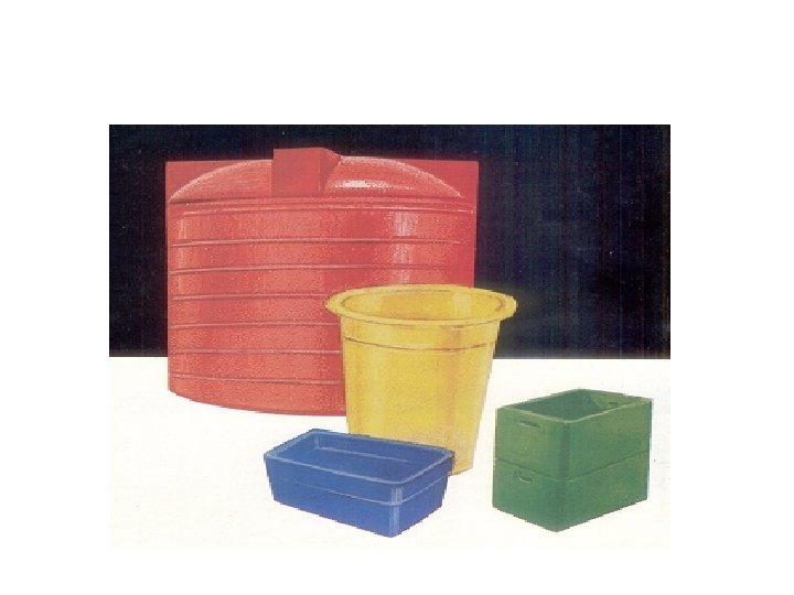
INTRODUCTION • Rotational moulding is a process of making hollow articles. • The part is formed inside a closed female mould. • In this process the mould rotates biaxially during heating and cooling cycle. • Rotational moulded pieces are stress free because the pieces are produced without any external pressure.
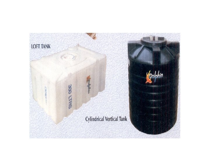
• The ability to manufacture large containers of capacity 30, 000 gallons as well as small items like golf ball is responsible for the growth of this process. • The Process requires relatively in expensive equipment and exerts on only small pressure on the material being formed.
PRINCIPLE • The principle of the process is that finely divided plastic material becomes molten when comes in contact with hot metal surface of the mould and takes up the shape of that surface. • As only female mould is used, the only pressure exerted are those induced by gravity and centrifugal force.
• The polymer is then cooled while still in contact with the metal mould to get the solid copy of the surface. • Rotational moulding permits to make a wide variety of fully and partially closed items. CORPORATE TRAINING AND PLANNING
ADVANTAGES AND DISADVANTAGES Advantages • The major advantage of rotational moulding as compared to other plastic moulding processes is that it can make very large parts. • It requires comparatively low cost input. • The products are stress free with strong out side corners. There are no weldlines, sprue or gate marks.
• Here impact toughness is improved and failure due to brittleness is reduced • The external dimensional details can be easily moulded with better surface glossiness. • The colour changes in the product can be made easily. Similarly mould changes can also be done rapidly. • Multilayer moulding is also possible for providing chemical resistance and strength to the part.
DISADVANTAGES • The moulding cycles are longer compared to blow moulding and thermoforming. • In case of big parts loading and unloading is very labour intensive. • The process is not suitable for parts with wall thickness less than 0. 03”. • The conversion of plastic granules to powder form increases the equipment and process cost.
LIMITATIONS 1. It is an open moulding process and so there are no cores inside the hollow parts 2. Surface details and dimensions can only be provided and controlled on the side of the part. 3. The process requires heating and cooling of not only plastic material but also the mould as well. 4. The long heating cycle increase the possibility of thermal degradation.
ROTATIONAL MOULDING PROCESS • Loading • Heating & Moulding • Cooling • Unloading
LOADING • This step includes weighing of the charge for a particular product then transferring it to the open cold mould. • The mould surface usually coated with a mould releasing agent. • The raw material can be in the form of powder or liquid state.
• The wall thickness can be controlled by varying the amount of raw material charged. • After the material is charged the mould is closed and clamped to the arm of the machine. • Then the mould is moved to an oven for heating
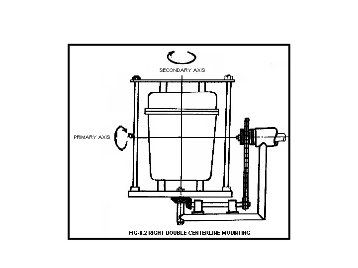
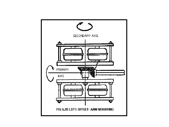
HEATING & MOULDING • The mould fixed to the arm now moved to a closed chamber where it undergoes intense heating. • During heating the mould rotates in two planes perpendicular to each other. • The rotational speed varies in the range of 0 -40 rpm on minor & 0 -12 rpm on the major axis. • 4: 1 ratio is the most commonly used for symmetric article.
• For moulding unsymmetrical products a wide variability of ratios is necessary. • The revolving motion distributes the plastic material uniformly over the inside surface of the mould. • The plastic material fuses into layers to form a hollow article. • In case of hot air oven the temperature should be between 200ºc to 500ºc.
• The moulding cycle time varies from 2 to 20 minutes depending upon the wall thickness of the article. • The wall thickness can vary from 2 to 12 mm or more. • The heating chamber should be large enough to house the mould and rotate it freely.
COOLING • For cooling the mould is transferred to the cooling station while still rotating. • The cooling should be made as quickly as possible to avoid the plastic part to shrink away form the mould. • Otherwise the part will get distorted. • Cooling can be done by air or water. To provide faster cooling cold water is sprayed over the mould.
UNLOADING • After cooling the mould is transferred to the unloading station. • In this step the mould is opened and the cooled part is taken out. • It can be done assistance. manually or with mechanical • The ejection can also be done by forced air. • The mould is cleaned and the charge is loaded for the next cycle.
HEATING SYSTEM IN ROTATIONAL MOULDING • The rotational molding process heats and cools both the mold and the plastic material. • Cavities are build up with materials having high thermal conductivity, in order to minimize the time required for heat to pass through the wall of the cavity.
• Rotational molds may be heated by either an open-flame method, a hot air re-circulating oven method, or by a hot-oil jacketed mold system. • Molten Salt-it leads to corrosion. • Infrared Heater-Very efficient but costly method. • The most used system is a re-circulating hot-air oven.
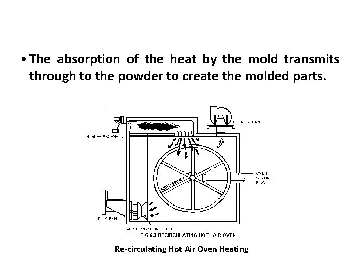
RE-CIRCULATING HOT AIR OVEN METHOD • In this system a positive displacement circulating fan distributes air through a system of ducts into the swept volume of the oven. • The capacity of the fan (cubic meters of air per minute), will determine the number of air changes per minute.
• On contemporary machines, air should be changed in the oven approximately 25 -30 times per minute in order to provide an effective heating for the mold. • Direction of the air in the oven is generally caused by the directional louvers so that no “dead spots” are created. • The static pressure capability of the fan system provides force to push the air over the mold and provide the scrubbing action of the hot air on the mold.
• The absorption of the heat by the mold transmits through to the powder to create the molded parts. Re-circulating Hot Air Oven Heating
• The medium for heating hot-air ovens may either be natural gas or oil with a modulating burner. • In some cases, electric heaters are used to generate the hot air environments. • The regulation of air temperature in the swept volume of the oven is controlled by sophisticated electronic temperature control devices. • The time that the mold remains in the oven is known as “Oven residence time”.
• The oven residence time necessary to cure a part will depend upon the wall thickness of the part, the type of plastic material being used to mold the part, and the conductivity of the metal of the mold. • Aluminum with a higher conductivity, allows heat to transfer from the air stream to the mold and the powder at a much faster rate than does steel. • Thinner gauge aluminum helps to increase the conductivity.
ROTATIONAL MOULDING MACHINES Three basic types of machines are : i. Batch type ii. Semiautomatic type iii. Continuous or rotary type
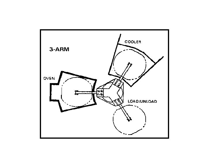
• Batch type is used in prototype or low volume production. This method requires less capital but most involvement of manual labour. • Continuous or rotary type method include three basic stations arranged 120º apart from arms attached to a central hub containing the drive mechanism. • Advantage of this system is minimal labour and high production rate.
ROTATIONAL MOULDING BY CAROUSEL-TYPE MACHINES • The carousel type machine is a three-station rotary indexing type with a central turret and three cantilevered mould arms. • Individual arms are involved in different operations simultaneously so that no arms are idle at any time. • All operations are automated and at the end of each cycle the turret is indexed 120º, thereby moving each mould arms to its next station.
• Newer carousel machines being offered today have four arms. • The additional arm can be used in a second oven, cooler or load station, depending on, which is the most time-consuming part of the over all cycle. • The four-arm carousel machines increase the production by allowing the indexing from station to occur more frequently than could be managed on a three-arm machines.
MULTILAYER ROTATIONAL MOULDING • It is used to combine two different colours of the same material or two dissimilar material into one part. • It offers potential advantages of increased stiffness. • When solid and foam are combined, improved barrier properties and permeation resistance by using thin inner or outer layer of low permeable material.
• It is a two staged process in which the skin of one material is combined with an inner layer of another material. • The first shot of material moulds in the normal fashion and the material adheres to the mould.
CASTING • Resin casting is a method of plastic casting where a mold is filled with a liquid synthetic resin, which then hardens. It is primarily used for small-scale production like industrial prototypes and dentistry. It can be done by amateur hobbyists with little initial investment, and is used in the production of collectible toys, models and figures, as well as small-scale jewellery production. • The synthetic resin for such processes is a monomer for making a plastic thermosetting polymer. During the setting process, the liquid monomer polymerizes into the polymer, thereby hardening into a solid. • Single-monomer resins may be used in the process, which form homopolymers (polymers containing only one type of polymer). • In such uses, the "curing agent" mixed with the resin contains what is loosely referred to as a "catalyst, " but which is more technically an initial source of free radicals (such as MEKP) to act as an initiator in a free-radical chemical chain reaction polymerization.
• Alternately, resin casting may be accomplished with a resin plus a nearly equal amount of a "hardener" liquid (as in many epoxy resin or polyester resinsystems), which functionally contains a second polymer, for use in forming a final product plastic which is a copolymer. Copolymers contain two different alternating chemical entities in the final polymer molecule. • Process Most commonly a thermosetting resin is used that polymerizes by mixing with a curing agent (polymerization catalyst) at room temperature and normal pressure. • The resins are named by analogy with plant resins, but are synthetic monomers for making polymer plastics. The so-called synthetic resins used include polystyrene resin, polyurethane resin, epoxy resin, unsaturated polyester resin, acrylic resin and silicone resin. • Epoxy resin has a lower viscosity than polyurethane resin; polyester resin also shrinks markedly while curing.
• Acrylic resin, in particular the methyl methacrylate type of synthetic resin, produces acrylic glass (also called PMMA, Lucite, Plexiglass), which is not a glass but a plastic polymer that is transparent, and very hard. • It is suitable for embedding objects (such as, for example, acrylic trophies), for display purposes. • Styrene is a similar liquid monomer at room temperature, which will also polymerize into clear glass-like polystyrene plastic, with addition of a suitable catalyst. • A flexible mold can be made of latex rubber, room temperature vulcanized silicone rubber or other similar materials at relatively low cost, but can only be used for a limited number of castings. • The simplest method is gravity casting where the resin is poured into the mold and pulled down into all the parts by gravity.
• When the two part resin is mixed air bubbles tend to be introduced into the liquid which can be removed in a vacuum chamber. • The casting can also be done in a vacuum chamber (when using open molds) to either extract these bubbles, or in a pressure pot, to reduce their size to the point where they aren't visible. • Pressure and/or centrifugal force can be used to help push the liquid resin into all details of the mold. The mold can also be vibrated to expel bubbles. • Each unit requires some amount of hands-on labor, making the final cost per unit produced fairly high. This is in contrast to injection molding where the initial cost of creating the metal mold is higher, but the mold can be used to produce a much higher number of units, resulting in a lower cost per unit.
Machining Plastic Parts
Outline • Why Machine Plastics • Process Considerations • Material Considerations
Why Machine Plastic? • Cost Effective – Low Volume Production – Secondary Operations • Material Limitations – Thermosets – Composites – Ultra-High Mw Materials
Machining Plastics vs Metals • Ventilation Concerns • Annealing – To Avoid Warpage • Robust Fixturing • Tooling Considerations – Sharper – More Clearance (“Rake”)
Factors Affecting Cutting Action In Plastics • Heat – Thermal Conductivity < Metal • Resists Compressive Fracture • Factors Promoting Tensile Fracture: – Sharp Tools – Large Rake Angles
Factors Affecting Cutting Action In Plastics • Chip Formation – Want Continuous Flow Type • Smooth and Continuous • High Elastic Deformation
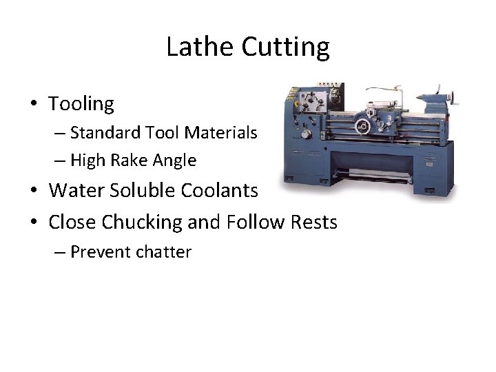
Lathe Cutting • Tooling – Standard Tool Materials – High Rake Angle • Water Soluble Coolants • Close Chucking and Follow Rests – Prevent chatter
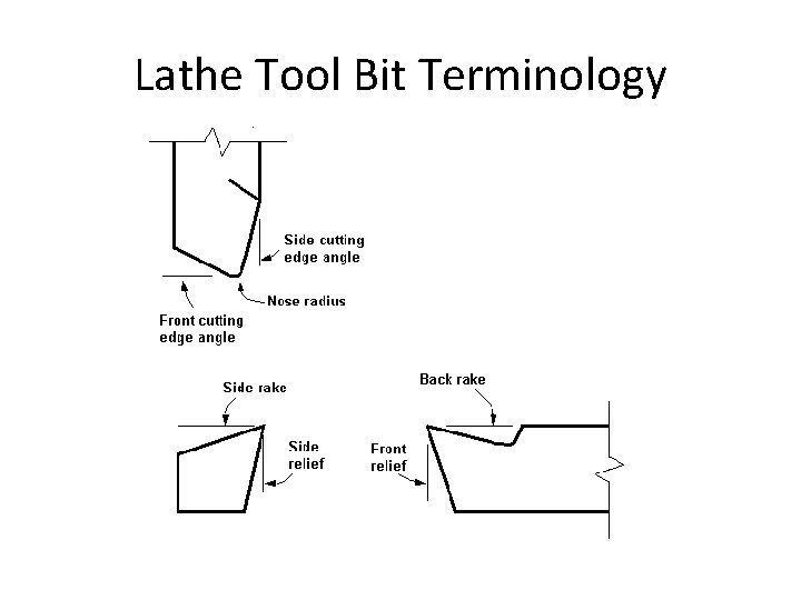
Lathe Tool Bit Terminology
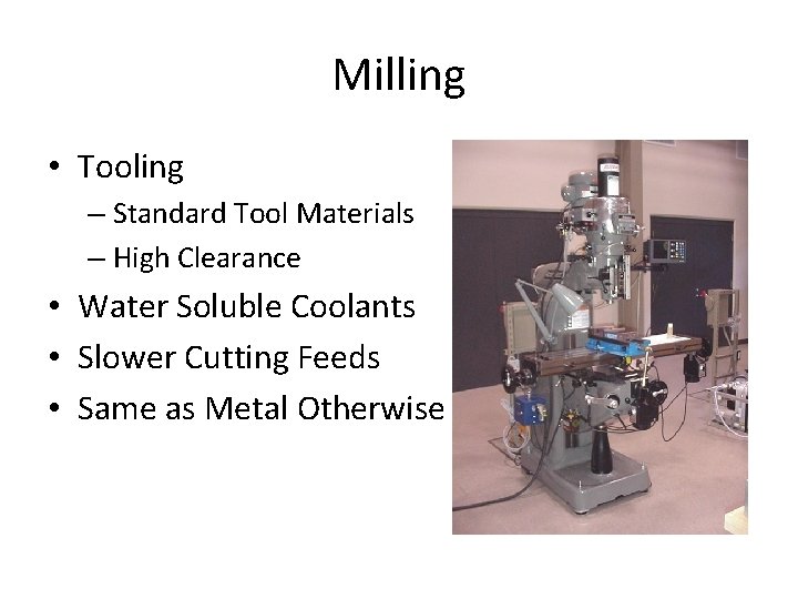
Milling • Tooling – Standard Tool Materials – High Clearance • Water Soluble Coolants • Slower Cutting Feeds • Same as Metal Otherwise
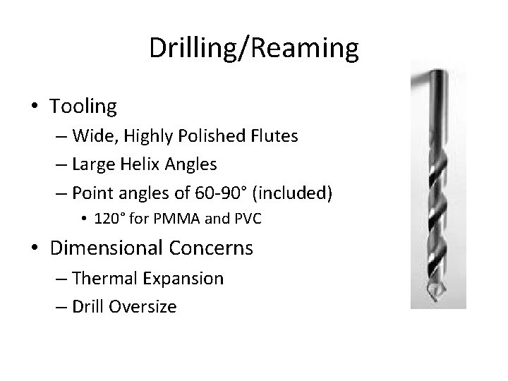
Drilling/Reaming • Tooling – Wide, Highly Polished Flutes – Large Helix Angles – Point angles of 60 -90° (included) • 120° for PMMA and PVC • Dimensional Concerns – Thermal Expansion – Drill Oversize
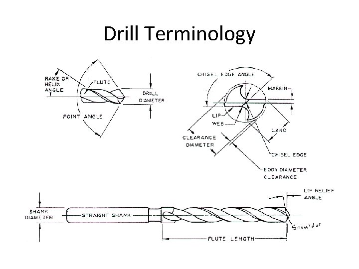
Drill Terminology
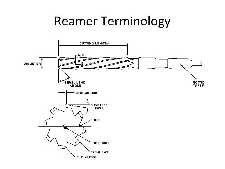
Reamer Terminology
Tapping/Threading • Tooling – Same Tools as Metal – Blunt Withdrawal Edges • Speeds – 50 ft/min Most Plastics – 25 ft/min Filled Materials
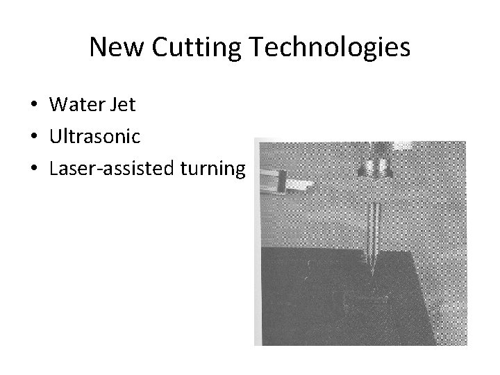
New Cutting Technologies • Water Jet • Ultrasonic • Laser-assisted turning
Material Specific Considerations
Machining Neat Plastics • Teflon, Acetal, Acrylics – Generous Rake – Low Cutting Speeds (< 1 m/min) • Nylon – Continuous Chips – Rake, Depth and Speed • Annealing – Standard – Double Anneal (Teflon)
Machining Thermosets • Base Resin Mixtures – Phenolic, Urea, Melamine, Silicone • Most similar to metal – High speeds and feeds – Finishing required
Machining Reinforced Plastics • Fiber-Reinforced Plastics (FRPs) • Base Materials – Polyesters, Polyamides, Expoxy Resins • Matrix (Filler) Materials – Glass, Carbon, Aramid Fibers
Machining Reinforced Plastics cont. • Usage Limitations • Chip/Dust Production • Surface Details – Unique Modes of Failure – Different Fracture Characteristics
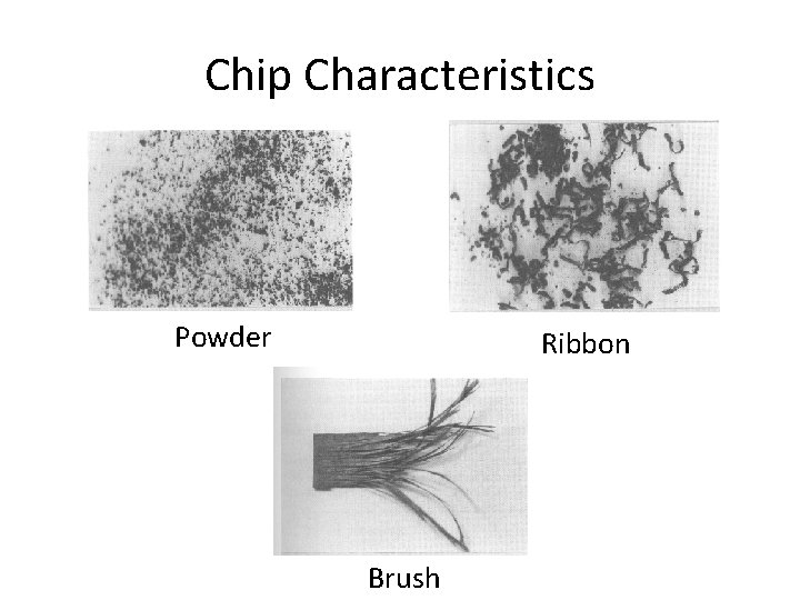
Chip Characteristics Powder Ribbon Brush
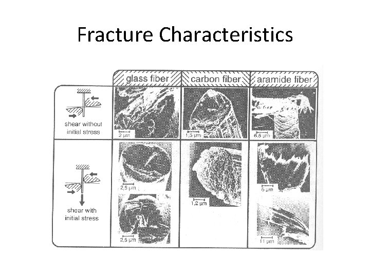
Fracture Characteristics
Machining Reinforced Plastics cont. • Tooling – Longer Life With K-Carbide • Cutting Speed 38 m/min – Single Crystal Diamond Tooling • Better Life • Cutting Speed 426 m/min
Conclusion • Cost Effective – Low Volume – Difficult to Mold Materials • Promote Tensile Fracture – Continuous Flow Chips – Generous Rake – Sharp Tools • Low Cutting Speeds
JOINING OF PLASTICS Fasteners, Welding, & Bonding
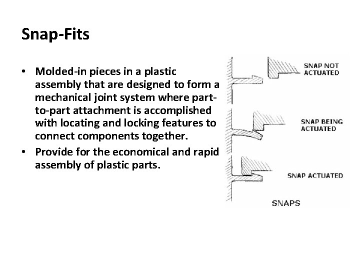
Snap-Fits • Molded-in pieces in a plastic assembly that are designed to form a mechanical joint system where partto-part attachment is accomplished with locating and locking features to connect components together. • Provide for the economical and rapid assembly of plastic parts.
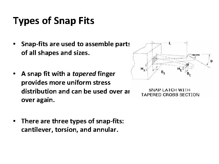
Types of Snap Fits • Snap-fits are used to assemble parts of all shapes and sizes. • A snap fit with a tapered finger provides more uniform stress distribution and can be used over and over again. • There are three types of snap-fits: cantilever, torsion, and annular.
Use of Snap-Fits • Snap-fits are often used for high-volume production. • In many products, snap-fits are designed for one-time assembly without any provision for nondestructive disassembly. – For example, snap-fit designs, such as those used in the plastic shell of small kitchen appliance or a child’s toy, are not designed to be taken apart without destroying the product. • Where servicing is anticipated, snap-fits can be designed that allow for release of the assembly with an appropriate tool. – For example, snap-fit designs, such as those used in battery compartment covers for calculators and radios, are designed for easy release and reassembly over hundreds or even thousands of cycles.
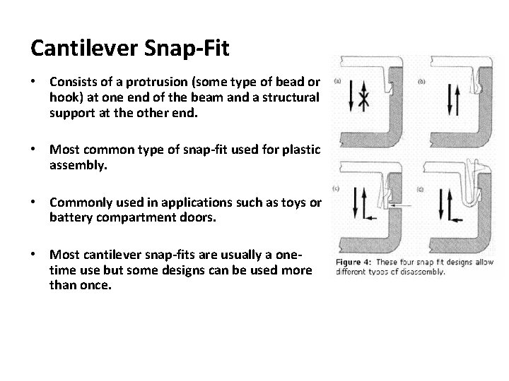
Cantilever Snap-Fit • Consists of a protrusion (some type of bead or hook) at one end of the beam and a structural support at the other end. • Most common type of snap-fit used for plastic assembly. • Commonly used in applications such as toys or battery compartment doors. • Most cantilever snap-fits are usually a onetime use but some designs can be used more than once.
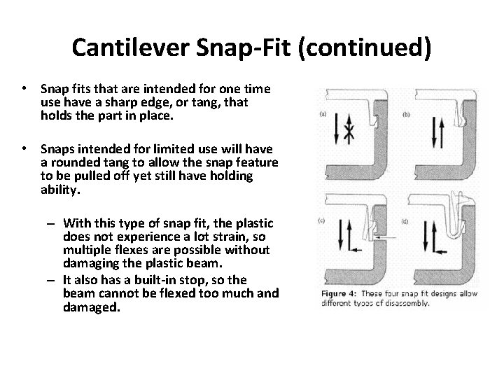
Cantilever Snap-Fit (continued) • Snap fits that are intended for one time use have a sharp edge, or tang, that holds the part in place. • Snaps intended for limited use will have a rounded tang to allow the snap feature to be pulled off yet still have holding ability. – With this type of snap fit, the plastic does not experience a lot strain, so multiple flexes are possible without damaging the plastic beam. – It also has a built-in stop, so the beam cannot be flexed too much and damaged.
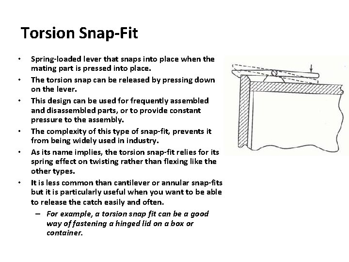
Torsion Snap-Fit • • • Spring-loaded lever that snaps into place when the mating part is pressed into place. The torsion snap can be released by pressing down on the lever. This design can be used for frequently assembled and disassembled parts, or to provide constant pressure to the assembly. The complexity of this type of snap-fit, prevents it from being widely used in industry. As its name implies, the torsion snap-fit relies for its spring effect on twisting rather than flexing like the other types. It is less common than cantilever or annular snap-fits but it is particularly useful when you want to be able to release the catch easily and often. – For example, a torsion snap fit can be a good way of fastening a hinged lid on a box or container.
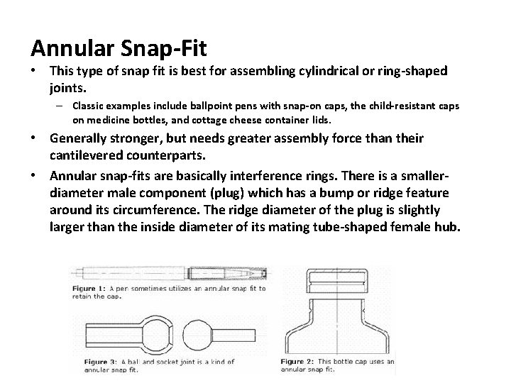
Annular Snap-Fit • This type of snap fit is best for assembling cylindrical or ring-shaped joints. – Classic examples include ballpoint pens with snap-on caps, the child-resistant caps on medicine bottles, and cottage cheese container lids. • Generally stronger, but needs greater assembly force than their cantilevered counterparts. • Annular snap-fits are basically interference rings. There is a smallerdiameter male component (plug) which has a bump or ridge feature around its circumference. The ridge diameter of the plug is slightly larger than the inside diameter of its mating tube-shaped female hub.
Benefits of Snap-Fits • An integral element of the plastic part – no other components are needed. • Can replace screws, nuts, and washers. • Easy automation can reduce assembly costs. • No other fastener, adhesive, solvent, welding, or special equipment is needed. • Design can minimize the risk of improper assembly. • Can be designed to engage and disengage.
Factors Regarding Snap-Fits • Snap-fits that are assembled under stress will allow creep, a plastic's deformation under load (tension, compression or flexure) over time. • It is difficult to design snap-fits with hermetic seals. If the beam or ledge of the snap-fit relaxes, it could decrease the effectiveness of the seal. • Snap-fits can be damaged by mishandling and abuse prior to assembly. • The key to successful snap-fit design is to have adequate holding power without exceeding the elastic or fatigue limits of the material.
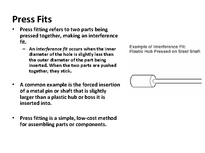
Press Fits • Press fitting refers to two parts being pressed together, making an interference fit. – An interference fit occurs when the inner diameter of the hole is slightly less than the outer diameter of the part being inserted. When the two parts are pushed together, they stick. • A common example is the forced insertion of a metal pin or shaft that is slightly larger than a plastic hub or boss it is inserted into. • Press fitting is a simple, low-cost method for assembling parts or components.
Use of Press Fits • Used in the telecommunications and computer industries, as well as in automobiles, airplanes, office equipment, and consumer goods. • Press fitting is a lower quality fitting process. However, once a press fit is in place, it will not come loose. • The particular application dictates whether a press fit or other fastening method is used. Press fits are sometimes used to get a complete alignment between two pieces. • Press fits are also used to prevent bearings from spinning. It is a good fastening method for components that undergo temperature fluctuations, such as automotive assemblies. Regardless of the temperature, the interference fit or force between the two parts is always there.
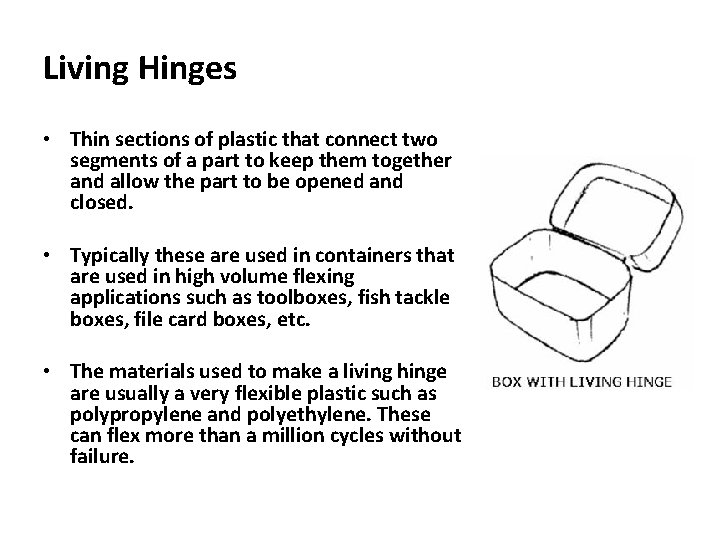
Living Hinges • Thin sections of plastic that connect two segments of a part to keep them together and allow the part to be opened and closed. • Typically these are used in containers that are used in high volume flexing applications such as toolboxes, fish tackle boxes, file card boxes, etc. • The materials used to make a living hinge are usually a very flexible plastic such as polypropylene and polyethylene. These can flex more than a million cycles without failure.
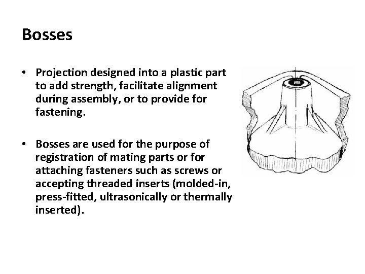
Bosses • Projection designed into a plastic part to add strength, facilitate alignment during assembly, or to provide for fastening. • Bosses are used for the purpose of registration of mating parts or for attaching fasteners such as screws or accepting threaded inserts (molded-in, press-fitted, ultrasonically or thermally inserted).
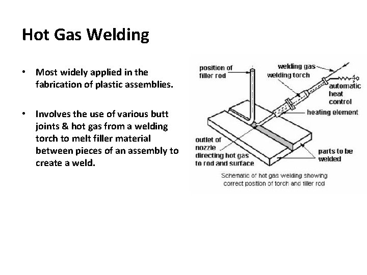
Hot Gas Welding • Most widely applied in the fabrication of plastic assemblies. • Involves the use of various butt joints & hot gas from a welding torch to melt filler material between pieces of an assembly to create a weld.
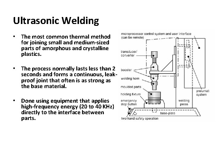
Ultrasonic Welding • The most common thermal method for joining small and medium-sized parts of amorphous and crystalline plastics. • The process normally lasts less than 2 seconds and forms a continuous, leakproof joint that often is as strong as the base material. • Done using equipment that applies high-frequency energy (20 to 40 KHz) directly to the interface between parts.
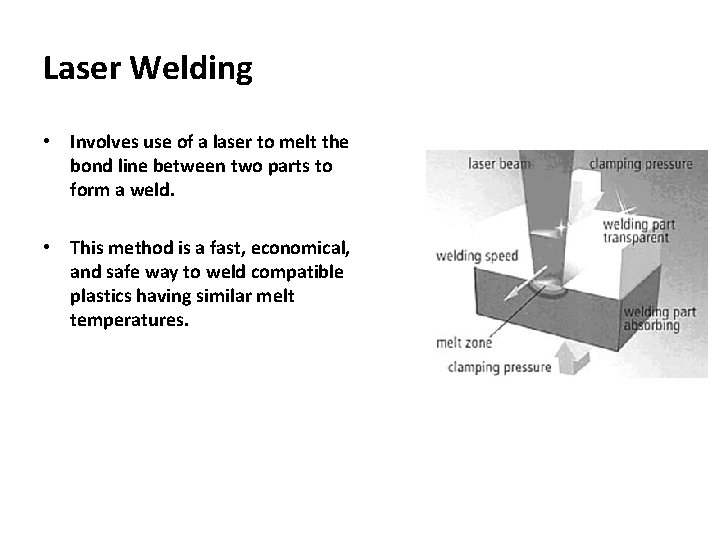
Laser Welding • Involves use of a laser to melt the bond line between two parts to form a weld. • This method is a fast, economical, and safe way to weld compatible plastics having similar melt temperatures.
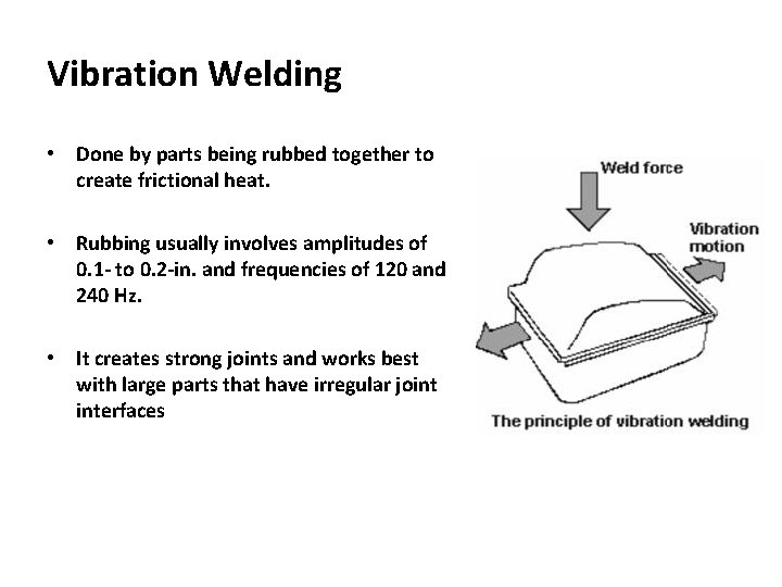
Vibration Welding • Done by parts being rubbed together to create frictional heat. • Rubbing usually involves amplitudes of 0. 1 - to 0. 2 -in. and frequencies of 120 and 240 Hz. • It creates strong joints and works best with large parts that have irregular joint interfaces
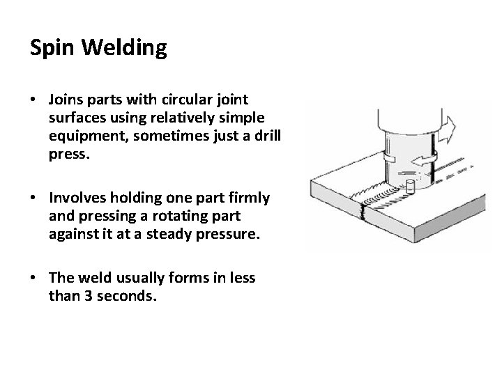
Spin Welding • Joins parts with circular joint surfaces using relatively simple equipment, sometimes just a drill press. • Involves holding one part firmly and pressing a rotating part against it at a steady pressure. • The weld usually forms in less than 3 seconds.
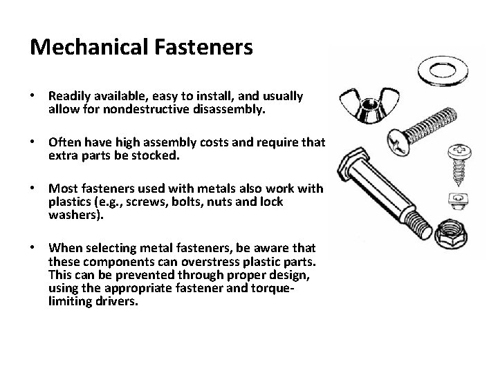
Mechanical Fasteners • Readily available, easy to install, and usually allow for nondestructive disassembly. • Often have high assembly costs and require that extra parts be stocked. • Most fasteners used with metals also work with plastics (e. g. , screws, bolts, nuts and lock washers). • When selecting metal fasteners, be aware that these components can overstress plastic parts. This can be prevented through proper design, using the appropriate fastener and torquelimiting drivers.
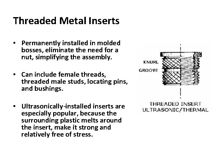
Threaded Metal Inserts • Permanently installed in molded bosses, eliminate the need for a nut, simplifying the assembly. • Can include female threads, threaded male studs, locating pins, and bushings. • Ultrasonically-installed inserts are especially popular, because the surrounding plastic melts around the insert, make it strong and relatively free of stress.
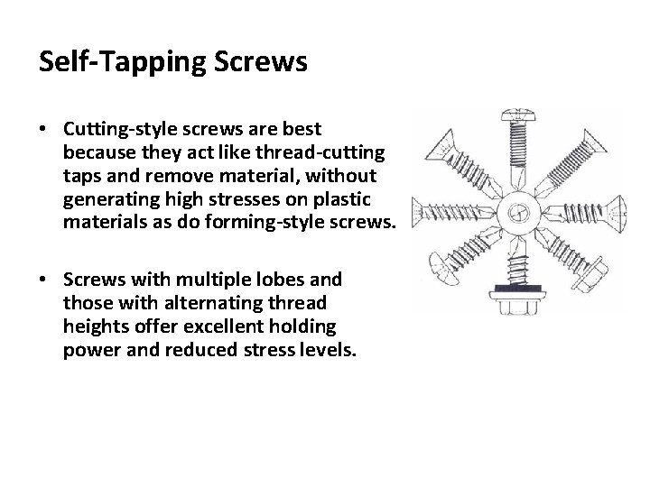
Self-Tapping Screws • Cutting-style screws are best because they act like thread-cutting taps and remove material, without generating high stresses on plastic materials as do forming-style screws. • Screws with multiple lobes and those with alternating thread heights offer excellent holding power and reduced stress levels.
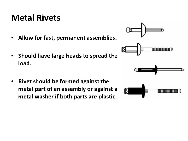
Metal Rivets • Allow for fast, permanent assemblies. • Should have large heads to spread the load. • Rivet should be formed against the metal part of an assembly or against a metal washer if both parts are plastic.
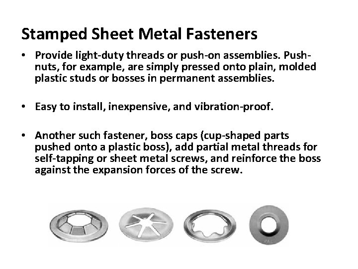
Stamped Sheet Metal Fasteners • Provide light-duty threads or push-on assemblies. Pushnuts, for example, are simply pressed onto plain, molded plastic studs or bosses in permanent assemblies. • Easy to install, inexpensive, and vibration-proof. • Another such fastener, boss caps (cup-shaped parts pushed onto a plastic boss), add partial metal threads for self-tapping or sheet metal screws, and reinforce the boss against the expansion forces of the screw.
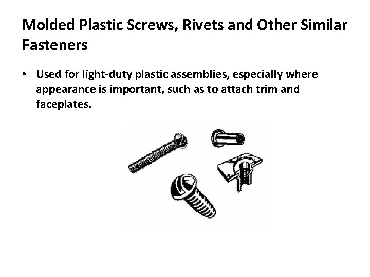
Molded Plastic Screws, Rivets and Other Similar Fasteners • Used for light-duty plastic assemblies, especially where appearance is important, such as to attach trim and faceplates.
Solvent Bonding • A liquid applied just before assembly dissolves the joint surfaces. This is enough for a weld to remain after the solvent evaporates. This method is limited to compatible materials that dissolve in the same solvent or solvents. • The chemical resistance of many plastics limit this method from being used.
Adhesive Bonding • Occurs when a third substance bonds a plastic to another plastic or to metal, rubber, ceramic, glass, or wood. • Adhesives frequently used with thermoplastics include epoxy, acrylic, polyurethane, phenolic, rubber, polyester and vinyl. Cyanoacrylate (superglue) adhesives are popular because they work rapidly. • Many adhesives contain solvents that partially dissolve the plastic surface, which improves adhesion. • Surface preparation is also critical for successful adhesion. • Many materials must be roughened or etched to eliminate overly smooth surfaces. They also may need thorough cleaning because grease, mold release compound, and other contaminants can spoil a bond.