Rotational Linear Velocity Acceleration Motion Angular Velocity Angular

 (perpendicular distance) (Fig 1 -2. ) (J: moment")


 , 2. Increase Velocity")


")
 X X Force South pole X Angular velocity X Zero")


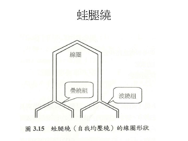
 折疊 波繞")


")


- Slides: 64
Rotational • Linear Velocity • Acceleration Motion . Angular Velocity . Angular
Newton’s Law of Rotation (force applied) (perpendicular distance) (Fig 1 -2. ) (J: moment of Inertia. )
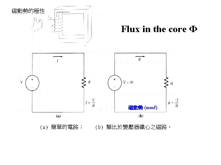
Magnetic Field 磁場 安培定律是說明電流產生磁場的基本定律。 • Ampere’s Law I • Magnetic Field Intensity H
Magnetic Flex Φ, B • Magnetic Flex Φ • Magnetic Flex Density B
EX 1 -2 given : B, N, R find: R, Ф, I
EX 1 -3 given : N, I, R find: R, Ф
1. 6 Induced Force on a wire Motor action I
1. 7 Induced Voltage + _
1. 8 the Linear DC Machine Fig 1 -19.
Starting the DC Machine
Linear DC Machine Behaves: 1. At Start: 2. Force: 3. Accelerate: 4. Reduce I : 5. Decrease F: 6. At F=0; 7. Move at a constant speed
Linear DC Machine as a Motor: is applied to the bar: 1. 2. 3. 4. 5. Bar begins to slow down, Induced voltage drops Decrease current: Increase Until; Fig 1 -23
Linear DC Machine as a Generator 1. Applied force (right) , 2. Increase Velocity v 3. Induced Voltage 4. With 5. Current 6. Induced force 7. 8. , (Battery is charging)
http: //www. mpoweruk. com/machines. htm
DC Machine
DC Machinery Fundamentals
DC Gen
DC & AC Gen
DC Generator
The Induce Torque
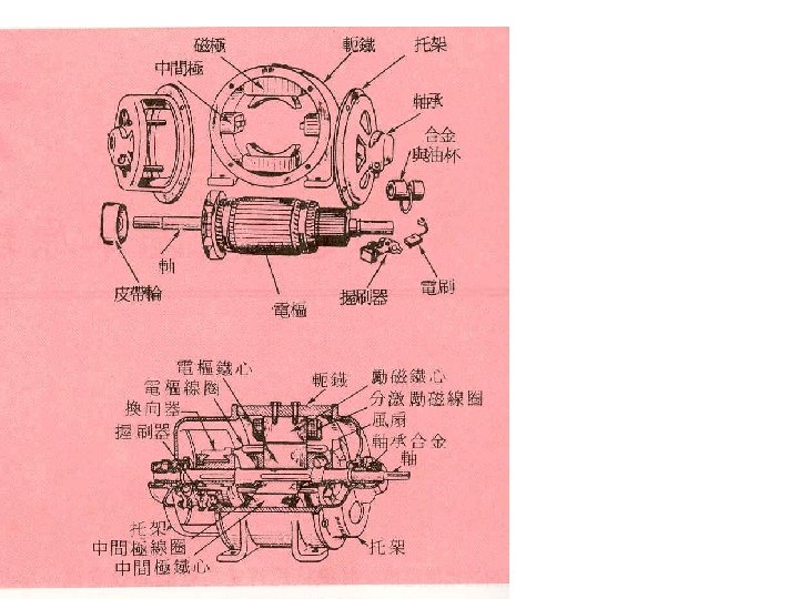
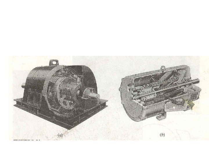
Structure
Ex 8 -1 Give: a. Switch closed Steady state:
b. Starting condition Noload steady-state condition
C. load torque is applied ; 1. Speed decrease: …………………. 2. Rotor current: …………… 3. 4. until:
Power supplied to the shaft: Power out of battery:
d. A Torque Is Applied in Direction of Motion , a. The rotor accelerates ; Speed increase
D b. c. d. (charge)
DC machine basics(換相 ) X X Force South pole X Angular velocity X Zero Force North pole
換相 Commutation
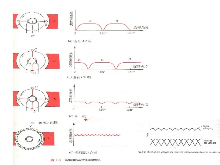
Basic theory
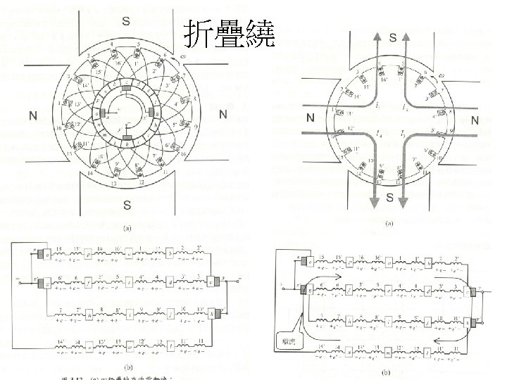
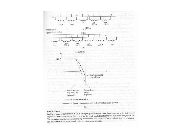
8. 2 Commutation (2 P) 折疊 波繞
Lap-wound A lap winding is m-plax; Pitch: Current path: 折疊
Lap-Wound
The Wave Winding Pitch: Multiplex wave C is the number of coil on the rotor. Current path:
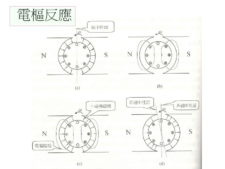
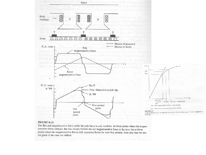
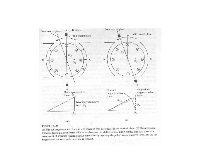
8. 4 Problems With Commutation Armature Reaction Neutral-plane shift a. Arcing and sparking b. Total average flux is decrease flux weakening. (8 -24 8 -25) Voltage will be induced in the …. commutation segment.
Armature Reaction
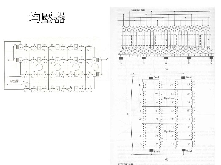
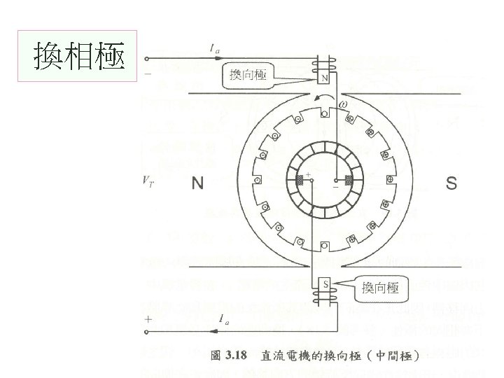
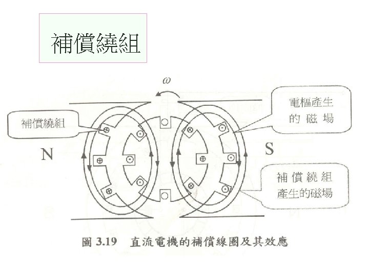
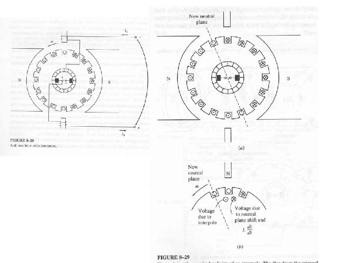
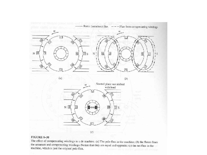
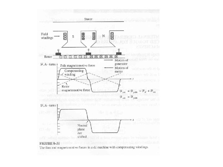
Solutions to the Problems With Commutation Three approaches have been developed to correct the problems of armature reaction and voltage. 1. Brush shift(depend on load; G; M 2. Commutating poles or interpoles 3. Compensating winding )
Basic theory
Ex 3. 3
Ex 3. 4
Ex 3. 4 b
Ex 3. 4 c
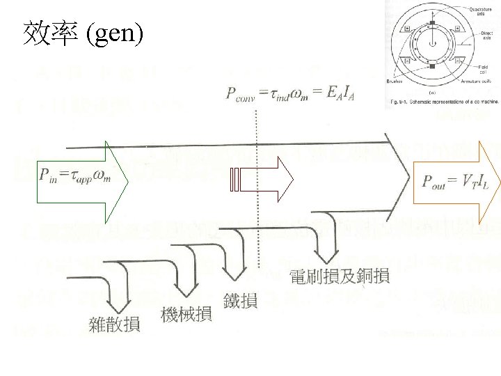
效率 與 損失 1. Copper Losses: 2. Core losses a. hysteresis loss b. eddy current loss 3. Mechanical Losses 4. Stray Losses (Miscellaneous Losses )
效率 (motor)
Losses Generator Motor
Voltage Regulation