Rotary cutting instruments Historical development Rotary speed ranges


 ¢ medium or")
 ¢ b. Low speed")
 It has been observed clinically low speed requires 2 -5 pounds force,")


 shank, (2) neck, and (3) head.")


 is advocated")


 instruments.")


 ¢ Medium")


- Slides: 84
Rotary cutting instruments
¢ Historical development. ¢ Rotary speed ranges. ¢ Instrument design. ¢ General Design of Dental Burs & associated terminology. ¢ Dental Abrasive Stone. ¢ Cutting mechanisms. ¢ Hazards with rotary cutting instruments.
Historical development ¢ cutting - thick, bulky chisels and excavators. ¢ The chisel was used to gain entrance through the carious dentin and make its removal possible by hand excavators.
1728 – HAND ROTATED INSTRUMENT. Taft described them as "bur drills". ¢
¢ 1850
¢ 1728 ¢ 1871 ¢ 1874 ¢ 1914 ¢ 1942 ¢ 1946 Hand-rotated 300 instruments Foot engine 700 Electric engine 1000 Dental unit 5000 Diamond cutting 5000 instruments Old units converted to 10, 000 increase speed
1947 Tungsten carbide bur 12, 000
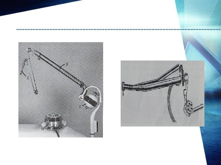
GEAR DRIVEN HANDPIECE ¢ Rotary power is tansferred to the straight handpiece by a belt that runs from electric engine over a series of pulleys & a 3 piece extension cord arm. ¢ Function best at low speed because of so many moving parts with metal to metal contact.
Water Driven Handpiece o 1955 Turbo-jet o Designed as compact mobile unit & only electricity is needed to operate it. o
¢A soundproof cabinet contain a motor, water pump , water reservoir & plumbing for circulating the water. ¢ Water is conveyed to & from the handpiece by a co-axial type tubing.
Belt Driven Handpieces ¢ 1955. Page. Chayes ¢ All gears were eliminated by having a small belt run inside the handpiece sheath over ball bearing pulleys in the angle sections. ¢ Improved models -Page-Chayes 909 and the Twin 909 ¢
Air Driven Handpieces ¢ 1957 ¢A small compact unit consists of a handpiece, control box, foot control and various connector hoses. ¢ When the foot control is activated, compressed air flows through the control box and is carried by a flexible hose to the back of the handpiece.
¢ From here the air is directed to the head of the handpiece and is blown against the blades of a small turbine to produce rotation while the greater, part is exhausted at the back of the handpiece or returned to the control box.
¢ The electric motor high-speed handpiece performed as well as, but not better than, the air turbine high-speed handpiece in the fabrication of highquality cavity preparations. (J Am Dent Assoc, 2005, Vol 136, No 8, 1101 -1105 )
ROTARY SPEED RANGES Acc. to Charbonneau: ¢ Conventional of low speed Below 10, 000 rpm ¢ Increased or high speed 10, 000 to 150, 000 Rpm (maximum range of bell. Drivenequipment) ¢ Ultra speed Above 150, 00 rpm
According to Sturtevant ¢ low or slow speeds (below 12000 rpm) ¢ medium or intermediate speeds (12, 000 to 200000 rpm) ¢ high or ultrahigh speeds (above 200000 rpm).
Acc. to Marzuonk ¢ a. Ultra-low speed (300 -3000 RPM) ¢ b. Low speed (3000 -6000 RPM) ¢ c. Medium high speed (20, 000 -45, 000 RPM) ¢ d. High speed (45, 000 - 100, 000 RPM) ¢ e. Ultra-high speed (10, 000 RPM and more
Pressure (P) It has been observed clinically low speed requires 2 -5 pounds force, o high speed requires less force (1 pound) o ultra-high speed still less force (1 -4 ounces) for efficient cutting. o
Heat production Heat is directly proportional to ¢ 1. Pressure ¢ 2. RPM ¢ 3. Area of tooth in contact with the tool
Vibration ¢ Vibration is not only a major annoying factor for the patient, but it also cause fatigue for the operator. ¢ Vibration is a product of the equipment used and the speed of rotation.
The following criteria should be used in evaluating handpieces : Friction will occur in the moving parts of handpiece; especially the turbine. handpieces are equipped with bearings: ball bearing, needle bearings, glass and resin bearings, etc a.
b. Torque ¢ Torque is the ability of the handpiece to withstand lateral pressure on the revolving tool without decreasing its speed or reducing its cutting efficiency. ¢ Torque is dependent upon the type of bearing used and the amount of energy supplied to the handpiece.
C. Vibration ¢ While some vibration is unavoidable, care should be taken not to introduce it unnecessarily. ¢ Excessive wear of the turbine bearings, will cause eccentric running which creates substantial vibration.
DENTAL BURS ¢ All rotary cutting instruments that have-bladed cutting heads. This includes instruments intended for such purposes as finishing metal restorations and surgical removal of bone, & tooth preparation.
COMMON DESIGN CHARACTERISTICS ¢ three parts: (1) shank, (2) neck, and (3) head.
Shank Design ¢ part that fits into the handpiece, accepts the rotary motion from the hand -piece, and provides a bearing surface to control the alignment and concentricity of the instruments. ¢ straight handpiece shank, ¢ latch-type angle handpiece shank, ¢ friction-grip angle handpiece shank,
Neck Design ¢ intermediate portion of an instrument that connects the head to the shank. ¢ The main function of the neck is to transmit rotational and translational forces to the head.
Head Design ¢ working part of the instrument. ¢ the cutting edges or points that perform the desired shaping of tooth structure. bladed instruments Ø abrasive instruments Ø
Historical Development of Dental Burs earliest burs : ü expensive ü variable in dimension and performance • first machine made burs introduced in 1891
Carbide burs ¢ introduced ¢ All in 1947. carbide burs have heads of cemented carbide in which microscopic carbide particles, usually tungsten carbide, are held together in a matrix of cobalt or nickel.
¢ In most burs, the carbide head is attached to a steel shank and neck by welding or brazing. ¢ Although most carbide burs have the joint located in the posterior part of the head, others are sold that have the joint located within the shank and therefore have carbide necks us well as heads.
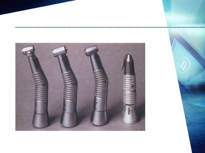
Bur Classification Systems BASED ON MODE OF ATTACTMENT TO HANDPIECE: ¢ latch-type ¢ friction-grip
COMPOSITION: Stainless steel o Tungsten carbide burs o combination o
MOTION: Right bur o Left bur o
LENGTH OF THEIR HEAD: Long o Short o regular o
USES: Cutting burs o Finishing & polishing burs o
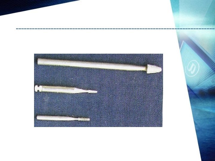
1. Head shapes o o o o round, inverted cone, pear, straight fissure, tapered fissure , Wheel shaped, End cutting bur
Round bur ¢ spherical . ¢ initial entry into the tooth , ¢ extension of the preparation, ¢ preparation of retention features/and caries removal. ¢ numbered from ¼, ½, 1, and 2 to 10.
Inverted cone bur ¢ providing undercuts in tooth preparations. ¢ numbered from 33¼, 33½, 34, 35 to 39.
Pear-shaped bur ¢A normal-length pear bur (length slightly greater than the width) is advocated for use in Class I tooth preparations for gold foil. ¢ long-length pear bur (length three times the width) is advocated for tooth preparations for amalgam. ¢ They are numbered from 229 to 333 and mainly used in pedodontics.
Straight fissure bur ¢ Elongated cylinder. ¢ amalgam tooth preparation. ¢ They are numbered from 555, 556 to 560.
Tapered fissure bur ¢ slightly tapered cone with the small end of the cone directed away from the bur shank. ¢ Tooth ¢ They preparations for indirect restorations. are numbered from 168, 169 to 172.
Wheel burs ¢ They ¢ are numbered as 14 and 15. They are wheel shape and are used to place grooves and for gross removal of tooth structure.
End cutting burs ¢ They are cylindrical in shape, with just the end carrying blades. ¢ ¢ They are very efficient in extending preparations without axial reduction. They are numbered from 900 to 904.
Modifications in Bur Design ¢ Reduced use of crosscut , ¢ extended heads on fissure burs , ¢ rounding of sharp tip angles.
General design of dental bur ¢ The dental burs are small milling (cutting) instruments.
CUTTING MECHANISMS ¢ For cutting, it is necessary to apply sufficient pressure to make the cutting edge of a blade or abrasive particle dig into the surface. ¢ The process by which rotary instruments cut tooth structure is complex and not fully understood.
BLADED CUTTING ¢ Tooth structure like any other brittle material undergoes both brittle and ductile fracture. ¢ Brittle fracture involves plastic deformation of a material usually proceeding with shear. ¢ Low speed tends to proceed by plastic deformation before tooth structure fractures. High speed cutting, especially of enamel proceeds with brittle fracture.
BLADED CUTTING ¢ the blade to initiate the cutting action, it must be sharp, have a higher hardness and modulus of elasticity than the material and must be pressed against the surface with sufficient force.
¢ Sheared segments accumulate in a distorted layer as it rotates. The chips that accumulate in the clearance space between blades until washed out or thrown out by centrifugal force.
¢ Mechanical distortion of the tooth surface ahead of the blade produces heat. ¢ Frictional heat is produces by both the rubbing action of the cut chips against the rake face of the blade and the blade tip against the cut surface of the tooth immediately behind the edge
¢ This can produce extreme temperature increase in both the tooth and the bur in the absence of adequate cooling.
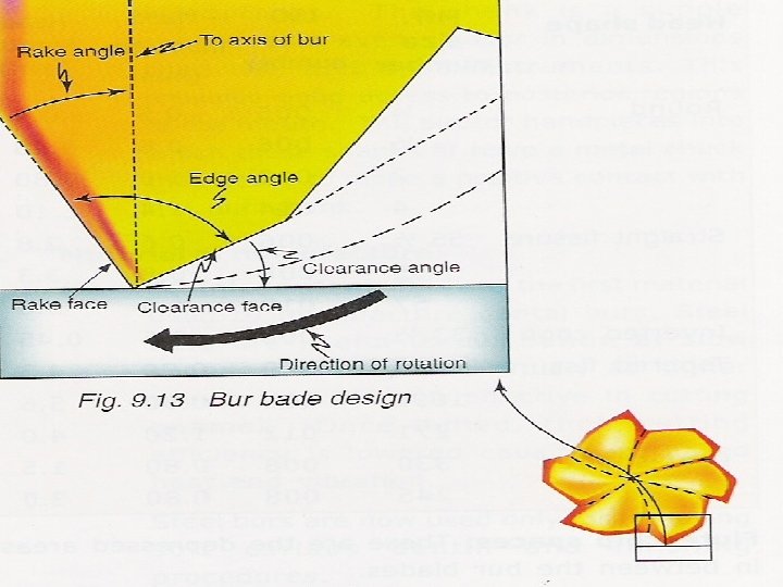
Factor influencing the cutting effectiveness & efficiency of a bur ¢ Rake angle, clearance angle & blade angle. ¢ Neck diameter. ¢ Spiral angle & crosscuts.
Concentricity & run-out ¢ Concentricity is a direct measurement of the symmetry of the bur head. ¢ It measures how closely a single circle can be passed through the tip of all the blades. ¢ It is an indication whether one blade is longer or shorter than the other. ¢ It is only a static measurement.
¢ Run-out refers to the eccentricity or maximum displacement of the bur head from its axis of rotation while the bur runs. ¢ clinically acceptable run-out is about 0. 023 mm.
¢ Heat treatment. ¢ Influence of load. ¢ Influence of speed. ¢ Number of teeth.
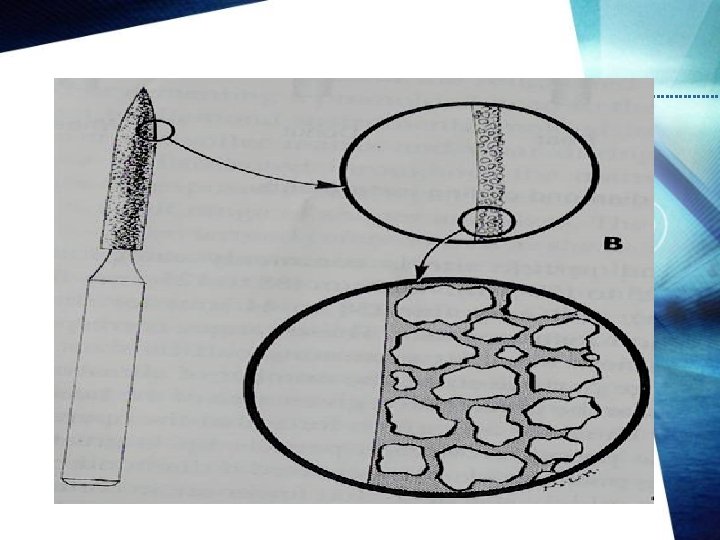
ABRASIVE INSTRUMENT
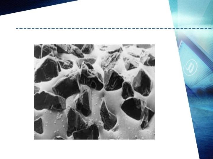
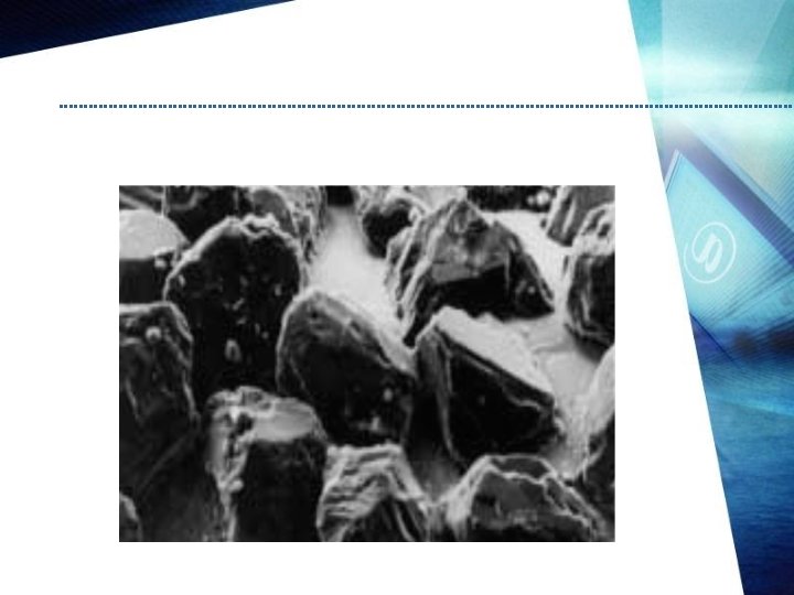
¢ Diamond stones ¢ They are hardest and most efficient abrasive stones for removing tooth enamel.
Carbides ¢ They may be silicon carbides or boron carbides. Sand ¢ Sand other forms of quartz (cuttle) can be bound and mounted into different shapes of discs, stones, and strips. Aluminum oxide o Natural or extracted pure aluminum oxide is one of the most efficient abrasives for stones in fine cutting.
Garnet ¢ These particles contain a number of different minerals which possess similar physical properties and crystalline forms. Stones made of these can be used for finishing and polishing of dental appliances
CLASSIFICATION ¢ Coarse grit diamond burs ( 125 -150 um particle size) ¢ Medium grit diamond burs (88 -125) ¢ Fine grit diamond burs (60 -74 ) ¢ Very Fine grit diamond burs (38 -44 )
Factors Influencing the Abrasive Efficiency of Dental Stones ; ü Size of abrasive particles. ü Shape of abrasive particles. Density of the abrasive particles. (Grajower etal 1979) density about -60 diamonds mm 2 cutting efficency –constant after 4 min. ü
ü Clogging of the abrasive particles. ü Hardness of the abrasive particles. ü Speed & pressure. ü Miscellaneous.
¢ Moulded ¢ Coated abrasive instrument.
Manufacture of diamond burs ¢ Electrodeposition ¢ 1 stage ¢ 2 stage ¢ Brazing ¢ Sintering JADA, VOI 129, JUNE 1998.
¢ CONVENTIONAL MIN. ¢ DISPOSABLE DIAMOND BUR— 60 -90 – 20 TO 30 MIN. L. CLERK, ABRASIVE TECHNOLOGY INC , ORAL COMMUNICATION , JAN 31 , 1994.
ABRASIVE CUTTING ¢ When diamond instrument are used to cut ductile materials, some material will be removed as chips, but much will flow laterally, around the cutting point and be left as a ridge of deformed material on the surface.
¢ Repeated deformation work hardens the distorted material until irregular portions become brittle and break of before being removed. ¢ This type of cutting is less effective than that of the blade; therefore burs are generally used for cutting ductile materials such as dentin.
¢ Diamonds cut brittle materials by a different mechanism. Most cutting results from tensile fractures that produce a series of subsurface cracks. ¢ Diamonds are most efficient when used to cut brittle materials and are superior to burs for the removal of dental enamel.
Disposable diamond abrasives ¢ Cleaning includes presoaking, hand scrubbing or ultrasonic cleaning and then drying before packaging for the sterilization process. ¢ Further, many manufacturers recommend that diamond burs be run against a sharpening stone before ultrasonic cleaning or that the tips be scrubbed with a wire brush to remove any organic debris before sterilization (M. Logan, Brasseler USA, oral communication, July 7, 1994)
STERILIZATION
HAZARDS WITH CUTTING INSTRUMENTS ¢ PULPAL PRECAUTIONS ¢ SOFT TISSUE PRECAUTIONS ¢ EYE PRECAUTIONS ¢ EAR PRECAUTIONS ¢ INHALATIONAL PRECAUTIONS
Advantages It is a familiar and well known procedure. ¢ Precision is obtained i. e. margins are clearly identifiable. ¢ It is easy to control the cutting ¢ The practitioner has tactile perception of the extent of cutting ¢
¢ Debris can be removed by water lavage and use of suction. ¢ Practitioner's vision while cutting is relatively good.
DISADVANTAGES ¢ Cutting with these instruments usually causes pain. ¢ Vibration caused by cutting usually cracks or fractures tooth structure. ¢ Noise produced with their use is objectionable. ¢ Constant use and sterilization cause them to breakdown.
¢ Dull burs produce lot of heat and potential pulp damage. ¢ Overcutting is easy if the operator loses control or the patient moves inadvertently.