
ROLLING STOCK REFERENCES IRCA Conference Rules pt III





- Slides: 130
ROLLING STOCK
REFERENCES IRCA Conference Rules, pt. III for Goods stock IRCA Conference Rules, pt. IV for Coaching stock Schedule of Dimensions Maintenance Manual for BG Coaches, 1995 Maintenance Manual for Wagons, 2001 RDSO’s Manual of Instructions (MI) for Coaching Stock – 105 kmph standard – 110 - kmph standard – Rajdhani standard • AC Traction Manual, Signal Manual etc • Various respective Instructions, Manuals and Circulars • • •
ROLLING STOCK • There are three distinct portions of rolling stock: • Wheel sets • Suspension system • Vehicle body
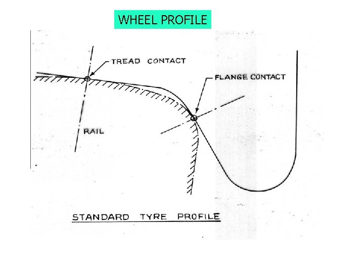
WHEEL PROFILE
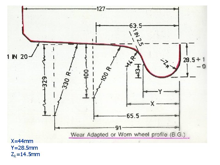
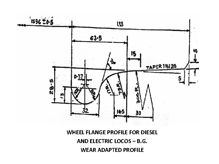
WORN WHEEL/WEAR ADAPTED PROFILE • Rail interaction with IRS wheel profile results in rapid wear of the flange and root of the flange during initial stages till a wear adapted/worn wheel profile is obtained • Since the wear after the worn wheel profile is obtained in service is considerably less, wheels are now provided with worn wheel/wear adapted profile
X=44 mm Y=28. 5 mm ZR=14. 5 mm
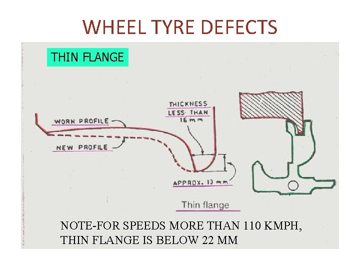
WHEEL TYRE DEFECTS THIN FLANGE NOTE-FOR SPEEDS MORE THAN 110 KMPH, THIN FLANGE IS BELOW 22 MM
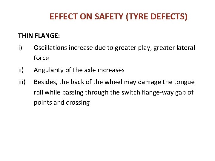
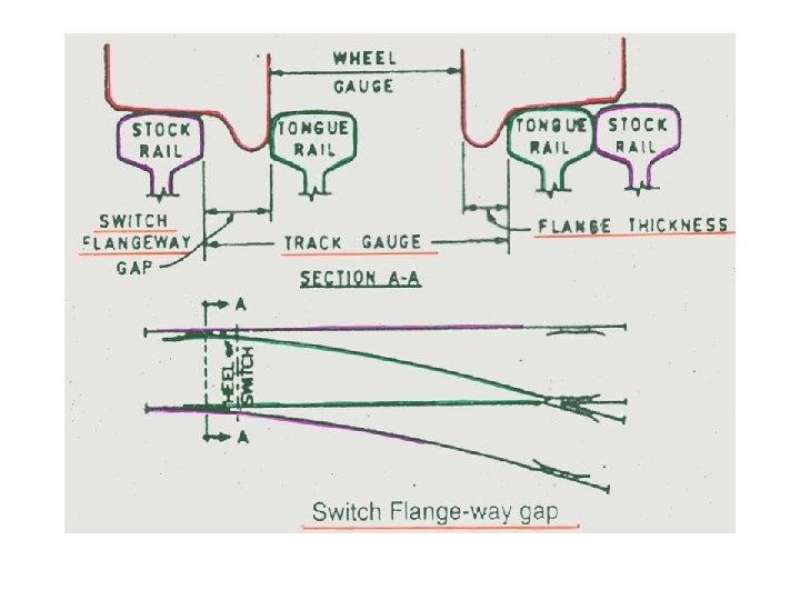
EFFECT ON SAFETY (TYRE DEFECTS) THIN FLANGE: i) Oscillations increase due to greater play, greater lateral force ii) Angularity of the axle increases iii) Besides, the back of the wheel may damage the tongue rail while passing through the switch flange-way gap of points and crossing
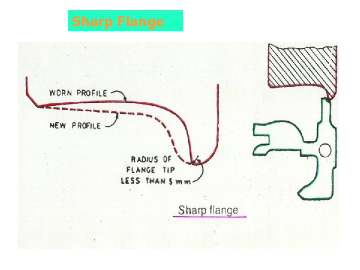
Sharp Flange
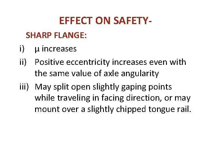
EFFECT ON SAFETYSHARP FLANGE: i) µ increases ii) Positive eccentricity increases even with the same value of axle angularity iii) May split open slightly gaping points while traveling in facing direction, or may mount over a slightly chipped tongue rail.
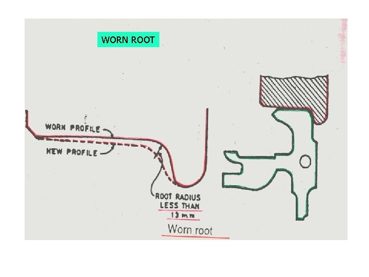
WORN ROOT
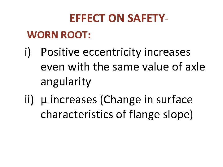
EFFECT ON SAFETYWORN ROOT: i) Positive eccentricity increases even with the same value of axle angularity ii) µ increases (Change in surface characteristics of flange slope)
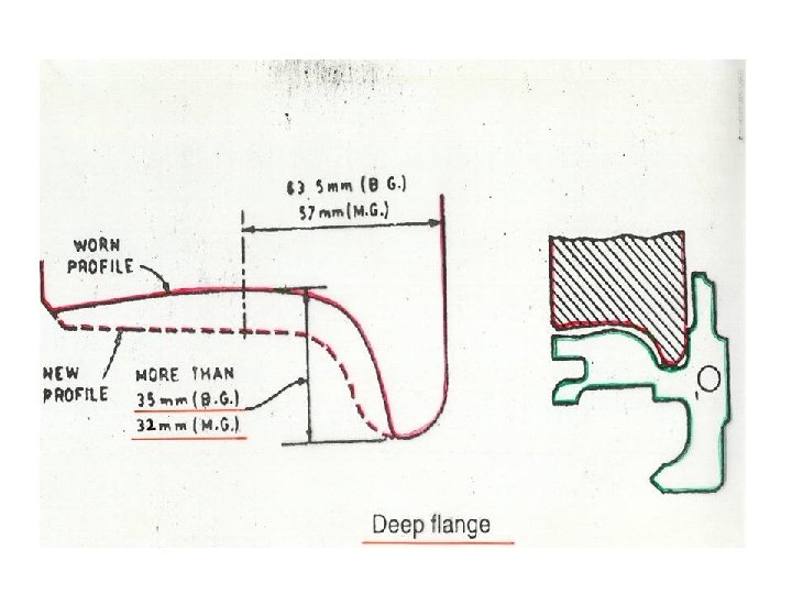
EFFECT ON SAFETYDEEP FLANGE • Deep flange coupled with vertical wear of the rail head would tend to ride on the fish plates and check / distance blocks-> not desirable
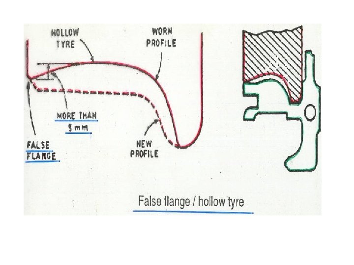
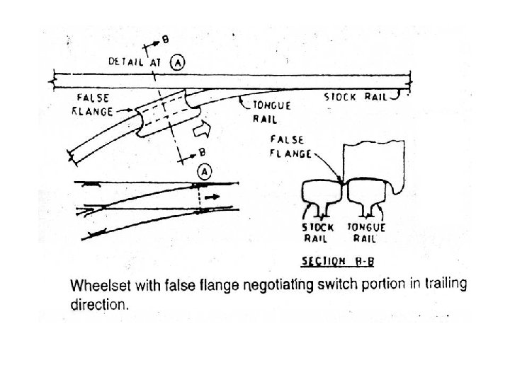
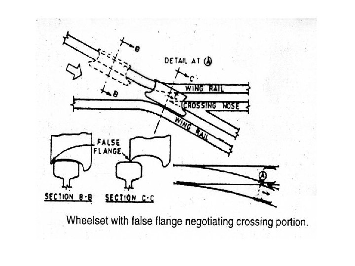
EFFECT ON SAFETYFALSE FLANGE / HOLLOW TYRE (i) May split open points while traveling in trailing direction (ii) May get suddenly lifted and dropped down near the nose of the crossing while negotiating the crossing.
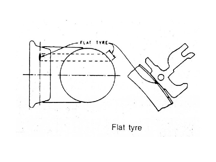
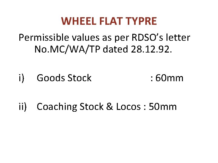
WHEEL FLAT TYPRE Permissible values as per RDSO’s letter No. MC/WA/TP dated 28. 12. 92. i) Goods Stock : 60 mm ii) Coaching Stock & Locos : 50 mm
EFFECT ON SAFETY- FLAT TYRE • Cause high dynamic augments on the rails. Rail stresses may get increased by 2½ times particularly at slow speeds of 20 -25 kmph • More awareness should be inculcated in all the staff to observe flat tyre and report.
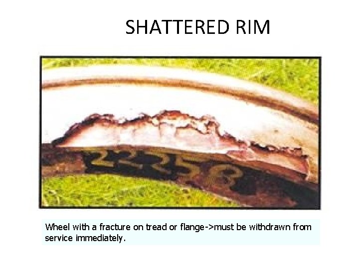
SHATTERED RIM Wheel with a fracture on tread or flange->must be withdrawn from service immediately.
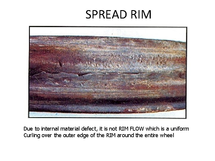
SPREAD RIM Due to internal material defect, it is not RIM FLOW which is a uniform Curling over the outer edge of the RIM around the entire wheel
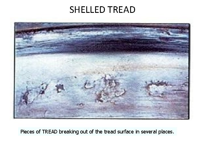
SHELLED TREAD Pieces of TREAD breaking out of the tread surface in several places.
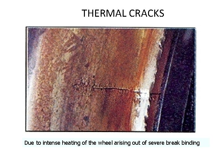
THERMAL CRACKS Due to intense heating of the wheel arising out of severe break binding
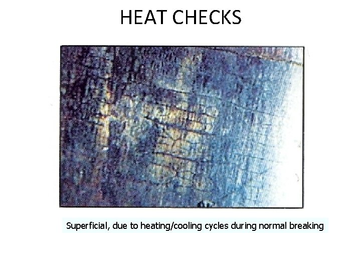
HEAT CHECKS Superficial, due to heating/cooling cycles during normal breaking
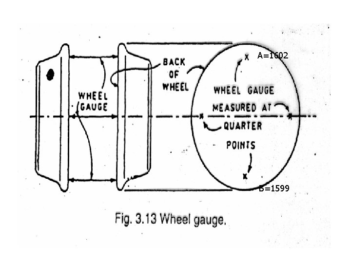
WHEEL GAUGE • To be checked at Quarter Points • COACHING /GOODS STOCK 1600 MM (1602 -1599) § No variation among the values of quarter points of same axle is permitted, § If variation-> a bent axle
A=1602 B=1599
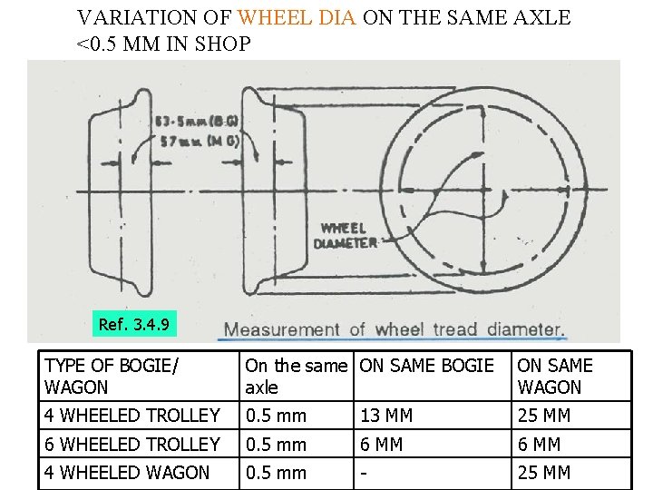
VARIATION OF WHEEL DIA ON THE SAME AXLE <0. 5 MM IN SHOP Ref. 3. 4. 9 TYPE OF BOGIE/ WAGON On the same ON SAME BOGIE axle ON SAME WAGON 4 WHEELED TROLLEY 0. 5 mm 13 MM 25 MM 6 WHEELED TROLLEY 0. 5 mm 6 MM 4 WHEELED WAGON 0. 5 mm - 25 MM
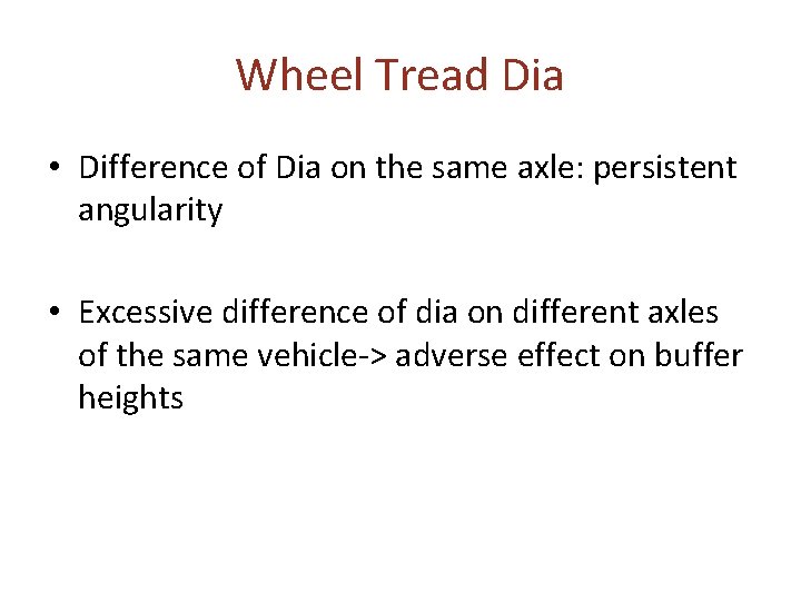
Wheel Tread Dia • Difference of Dia on the same axle: persistent angularity • Excessive difference of dia on different axles of the same vehicle-> adverse effect on buffer heights
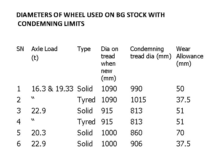
DIAMETERS OF WHEEL USED ON BG STOCK WITH CONDEMNING LIMITS SN Axle Load (t) Type 1 2 3 4 16. 3 & 19. 33 Solid 1090 “ Tyred 1090 22. 9 Solid 915 “ Tyred 915 990 1015 813 50 37. 5 51 51 5 6 20. 3 22. 9 860 906 70 37. 5 Solid Dia on tread when new (mm) 1000 Condemning Wear tread dia (mm) Allowance (mm)
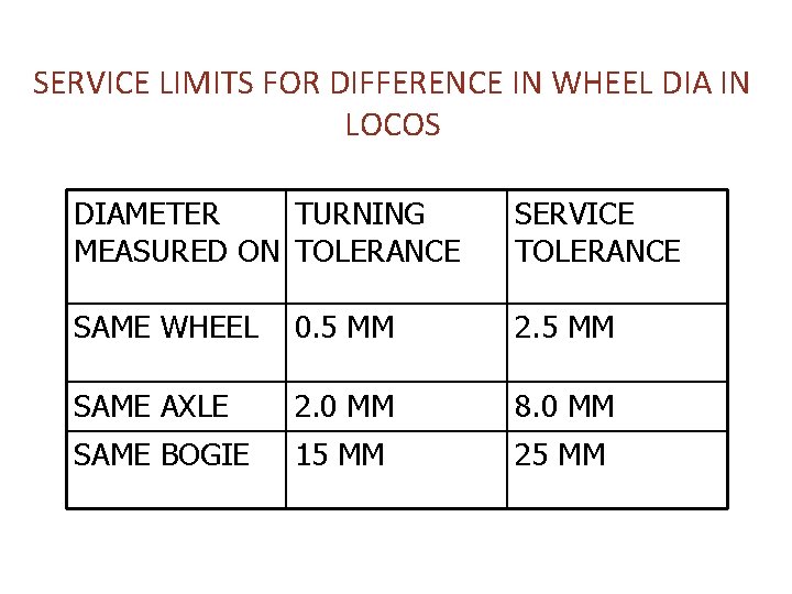
SERVICE LIMITS FOR DIFFERENCE IN WHEEL DIA IN LOCOS DIAMETER TURNING MEASURED ON TOLERANCE SERVICE TOLERANCE SAME WHEEL 0. 5 MM 2. 5 MM SAME AXLE 2. 0 MM 8. 0 MM SAME BOGIE 15 MM 25 MM
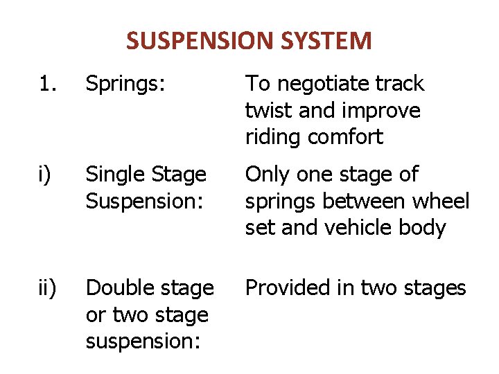
SUSPENSION SYSTEM 1. Springs: To negotiate track twist and improve riding comfort i) Single Stage Suspension: Only one stage of springs between wheel set and vehicle body ii) Double stage or two stage suspension: Provided in two stages
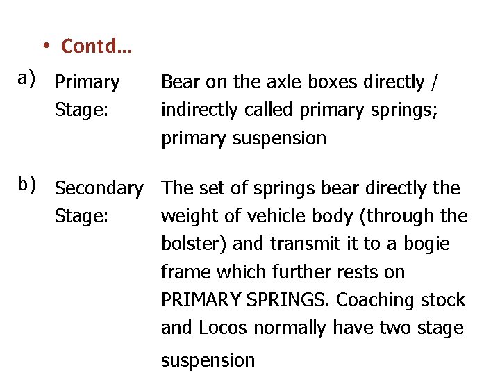
• Contd… a) Primary Stage: Bear on the axle boxes directly / indirectly called primary springs; primary suspension b) Secondary The set of springs bear directly the Stage: weight of vehicle body (through the bolster) and transmit it to a bogie frame which further rests on PRIMARY SPRINGS. Coaching stock and Locos normally have two stage suspension
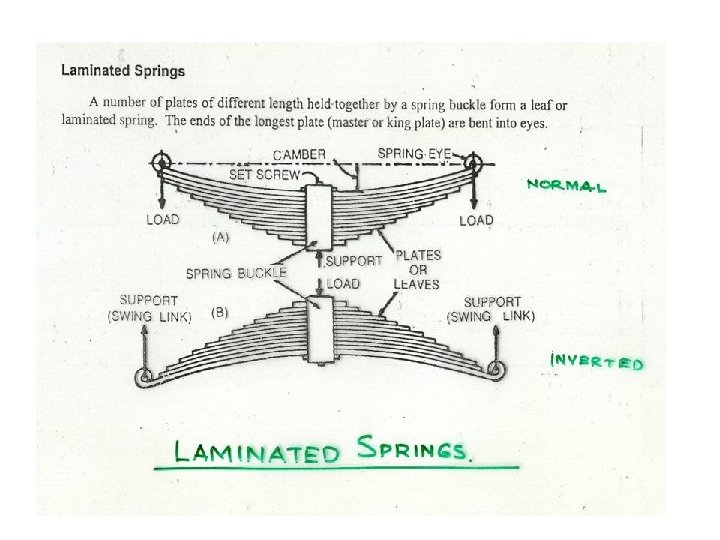
LAMINATED SPRINGS 1. GRADING: Springs are divided in 4 groups according to variation in camber w. r. t. nominal size viz; ‘A’, ‘B’, ‘C’ & ‘D’. It should be ensured that, all four springs of a wagon belong to the same group or one group higher or lower.
DEFECTS IN LIMINATED SPRINGS • FREE CAMBER: In general tolerances of measured free camber from design camber are: i) Loco & Carriage Springs-> – 0 +3 mm ii) Goods Stock, BG-> -0 +6 mm • WORKING CAMBER: Measured on a level track in loaded condition – In case of a 4 -wheeler wagon, difference in working camber between any two springs shall not exceed 13 mm (Worse if the difference on diagonally opposite springs)
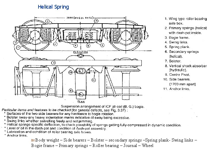
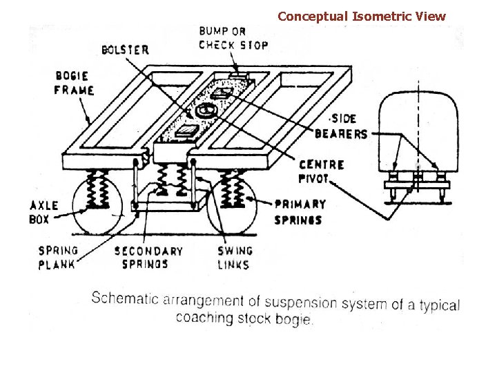
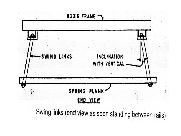
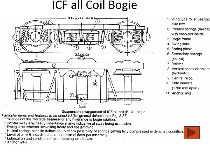
Helical Spring Body weight – Side bearers – Bolster – secondary springs –Spring plank- Swing links – Bogie frame – Primary springs – Roller bearing – Journal – Wheel
LAMINATED Vs HELICAL SPRINGS 1. Laminated springs require periodical attention and maintenance 2. Laminated springs provide excessive damping if not maintained properly 3. Laminated springs’ action is erratic 4. Some laminated spring assemblies are ineffective at high speed 5. Laminated springs required more raw material 6. Helical springs require use of dampers 7. Helical springs are of low weight
COMMON DEFECTS IN HELICAL SPRINGS 1. 2. 3. 4. Cracked or broken Shifted spring Spring fully compressed Loss of elasticity (fully compressed in dynamic condition) 5. Tapped with a light hammer. A dull sound would indicate the presence of crack or flaw.
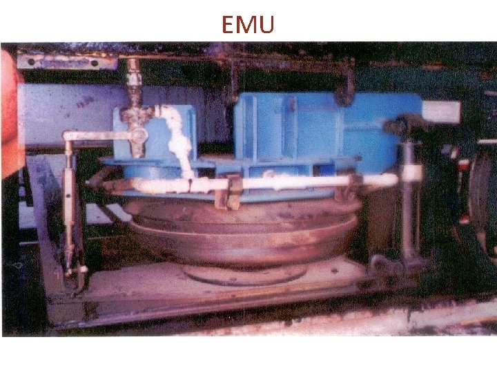
AIR SPRING • • • Ideal for passenger carrying vehicles and is used where there is a large payload ratio (pay load to tare weight) and a requirement to tailor the breaking effort to the vehicle mass Similar to a car tyre and is permanently connected to an auxiliary surge reservoir by an interconnecting pipe. The mass of air in the system is controlled by means of a mechanical levelling valve. In EMU trains of CR and WR
EMU
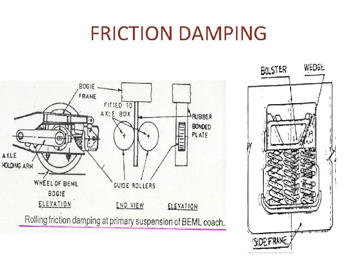
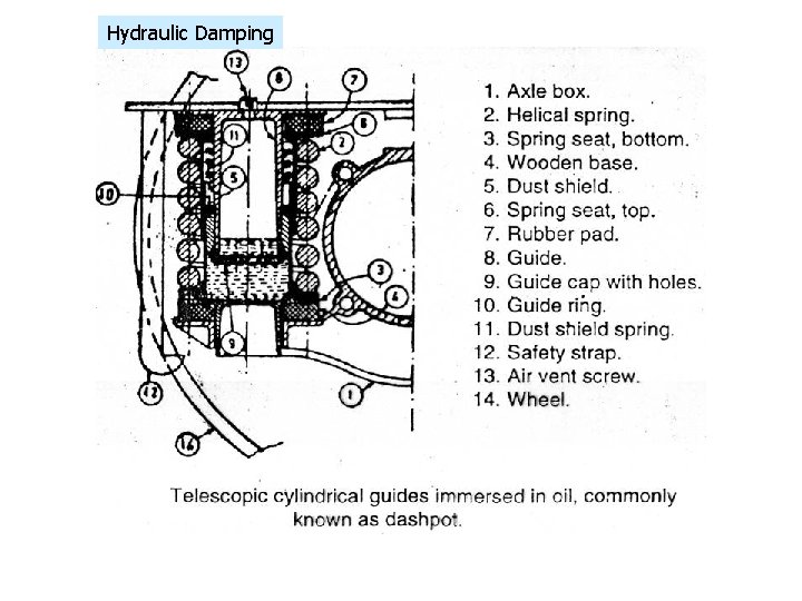
DAMPING • FRICTION DAMPING; laminated spring, also in BEML coaches • HYDRAULIC DAMPING-ICF all coil, locos
FRICTION DAMPING
Hydraulic Damping
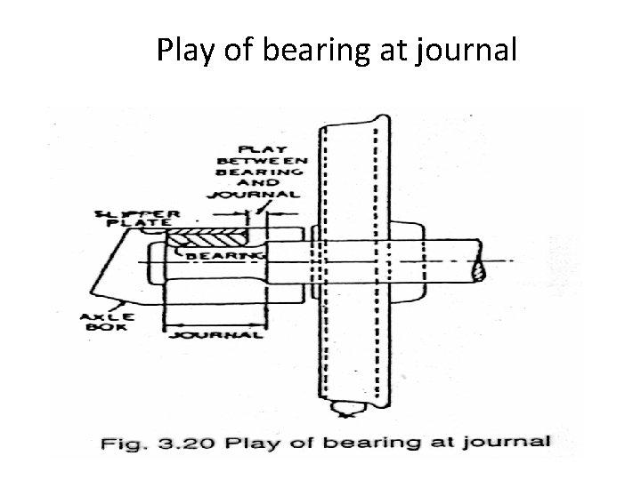
Play of bearing at journal
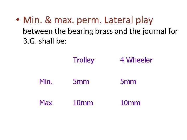
• Min. & max. perm. Lateral play between the bearing brass and the journal for B. G. shall be: Trolley 4 Wheeler Min. 5 mm Max 10 mm
AXLE GUARD HORN CHEEKS Ø to hold the axles in a rigid wheel-base Ø while performing the above function, to permit unhindered relative vertical movement between the vehicle body and the axle, to enable the springs to deflect and function freely
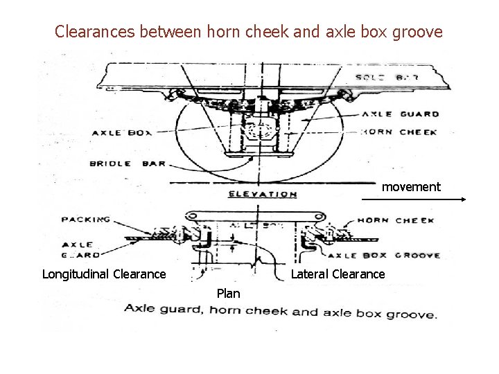
AXLE GUARD HORN CHEEKS • To have maximum life out of the axle guards, a piece called horn cheek is rivetted to the axle guard • It rubs against the groove surfaces. On wearing out, the horn cheek can be replaced by a new one without the need of replacing the entire axle guard.
Clearances between horn cheek and axle box groove movement Longitudinal Clearance Lateral Clearance Plan
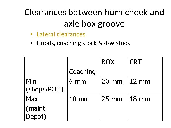
Clearances between horn cheek and axle box groove • Lateral clearances • Goods, coaching stock & 4 -w stock BOX CRT Coaching 6 mm 20 mm 12 mm 25 mm 18 mm Min (shops/POH) Max 10 mm (maint. Depot)
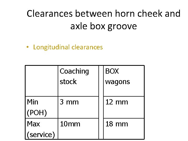
Clearances between horn cheek and axle box groove • Longitudinal clearances Coaching stock BOX wagons 3 mm 12 mm Max 10 mm (service) 18 mm Min (POH)
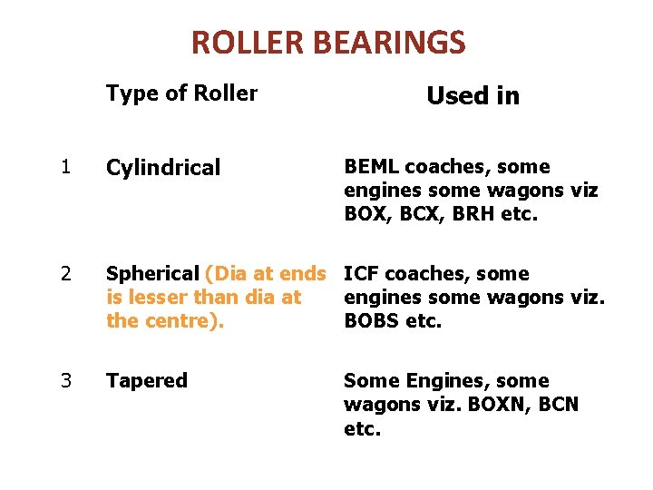
ROLLER BEARINGS Type of Roller Used in 1 Cylindrical 2 Spherical (Dia at ends ICF coaches, some is lesser than dia at engines some wagons viz. the centre). BOBS etc. 3 Tapered BEML coaches, some engines some wagons viz BOX, BCX, BRH etc. Some Engines, some wagons viz. BOXN, BCN etc.
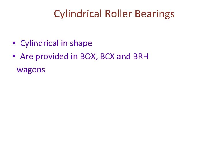
Cylindrical Roller Bearings • Cylindrical in shape • Are provided in BOX, BCX and BRH wagons
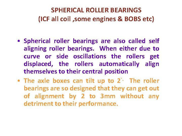
SPHERICAL ROLLER BEARINGS (ICF all coil , some engines & BOBS etc) • Spherical roller bearings are also called self aligning roller bearings. When either due to curve or side oscillations the rollers get displaced, the rollers automatically align themselves to their central position • The axle boxes can tilt up to 2°. The roller bearings are so designed that they can get out of alignment by 2 to 3 mm without any detriment to their performance.
TAPERED CATRIDGE (Some Locos, BOXN, BCN ) • These bearings are designed to take both radial and lateral loads. • It consists of 2 rows of tapered roller bearings kept apart by a spacer ring over the inner race • During the run the outer race is held firm in the adaptor and the inner race rotates along with the axle and the roller bearings, rotating about the axis of journal. • In case of any defect, the outer ring starts rotating under the adapter producing a loud whistling noise
PR Plates • On the left hand side of each sole bar or on the wagon body, PR plates are fitted or PR particulars are stenciled • P: Periodical overhaul of axle boxes • R: Re-examination and greasing of axle boxes
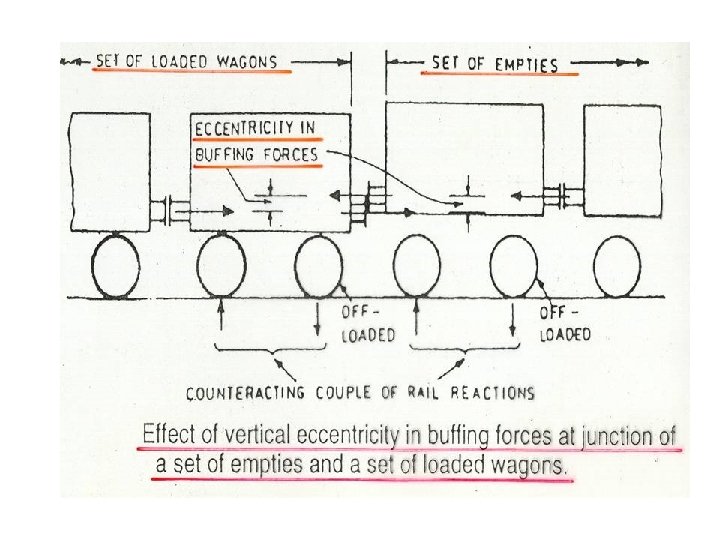
BUFFING GEARS/BUFFERS Performs the basic function of absorbing buffing impacts • Buffer defects have significant effect on derailment proneness • The effect is due to eccentricity of buffing forces Ø The eccentricity of buffing forces may be in vertical and/or horizontal direction •
DEFECTS RESULTING IN VERTICAL ECCENTRICITY BUFFING FORCES: (i) DIFFERENCE IN HEIGHT OF BUFFERS. Max. & Min. perm. Buffer heights BG (Goods & Coaching) Empty Loaded 1105 mm 1030 mm Note: To make up the buffer heights to max. permissible limits due to reduced dia of wheels, a packing piece of required design and size may be interposed between axle box crown and spring buckle
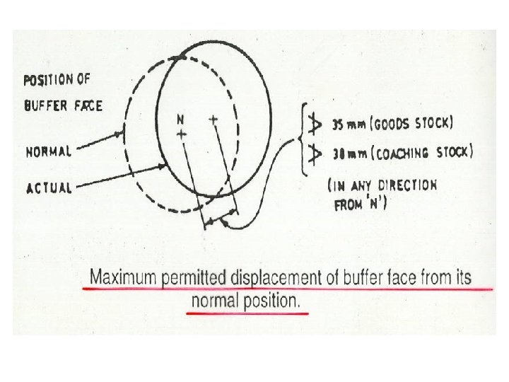
Contd. Defects in Buffer (ii) Drooping buffer; Buffer displaced vertically from its normal position due to headstock being bent. - On B. G. max. permitted displacement of buffer face due to head stock bent is 35 mm in any direction from its normal position for wagons and 38 mm for coaches
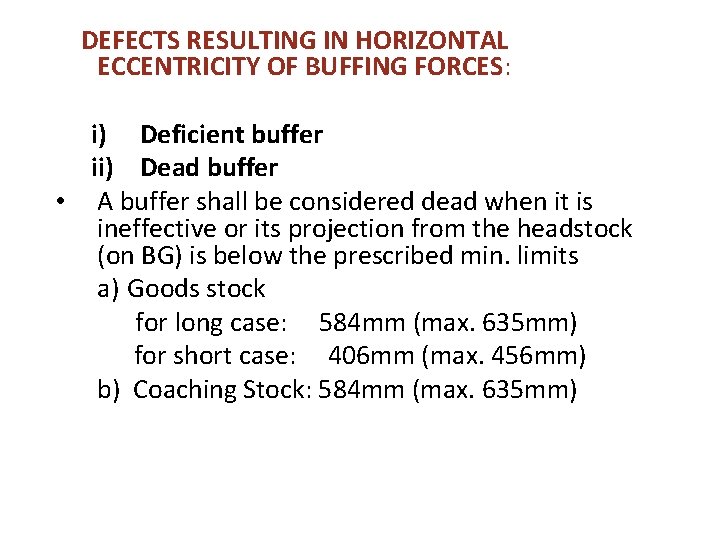
DEFECTS RESULTING IN HORIZONTAL ECCENTRICITY OF BUFFING FORCES: i) Deficient buffer ii) Dead buffer • A buffer shall be considered dead when it is ineffective or its projection from the headstock (on BG) is below the prescribed min. limits a) Goods stock for long case: 584 mm (max. 635 mm) for short case: 406 mm (max. 456 mm) b) Coaching Stock: 584 mm (max. 635 mm)
DEFECTS RESULTING IN ECCENTRICITY OF BUFFING FORCES IN BOTH DIRECTIONS • Buffer face is displaced from its normal position in an inclined direction, due to headstock being bent. • On B. G. maximum permitted displacement of buffer face due to headstock being bent is 35 mm in any direction from its normal position in case of wagons and 38 mm in case of coaching stock
BUFFERING GEAR DEFECTS - REJECTION 1. i) ii) GOODS STOCK If any buffer deficient More than one dead buffer on two consecutive wagons on a train iii) More than three rivets missing from a buffer plunger iv) Buffer spindle broken or nut deficient or of incorrect size
2. COACHING STOCK: i) Buffer deficient or drooping ii) Any buffer dead iii) Buffer spindle broken or nut deficient
• CAUSES FOR LOW BUFFER HEIGHT 1. 2. 3. 4. 5. Overloading Uneven loading Weak or defective springs Less dia of the wheel Worn out axle brass
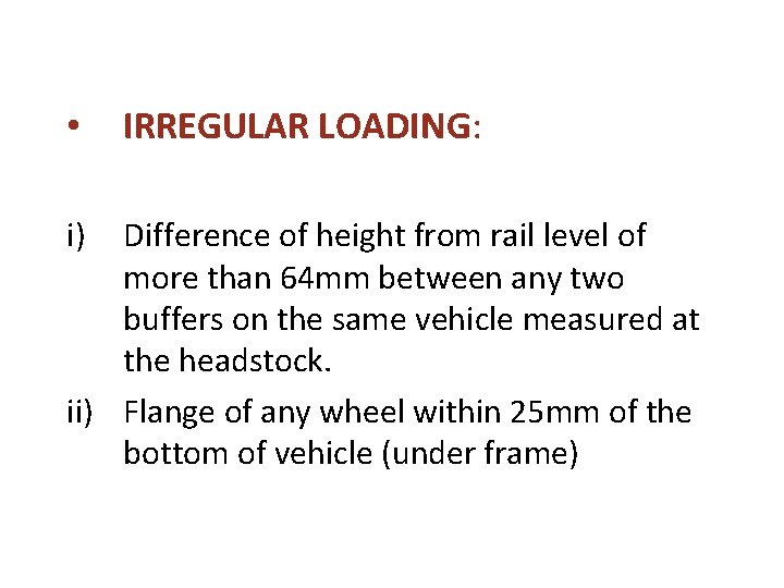
• i) IRREGULAR LOADING: Difference of height from rail level of more than 64 mm between any two buffers on the same vehicle measured at the headstock. ii) Flange of any wheel within 25 mm of the bottom of vehicle (under frame)
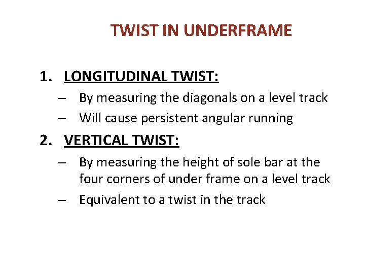
TWIST IN UNDERFRAME 1. LONGITUDINAL TWIST: – By measuring the diagonals on a level track – Will cause persistent angular running 2. VERTICAL TWIST: – By measuring the height of sole bar at the four corners of under frame on a level track – Equivalent to a twist in the track
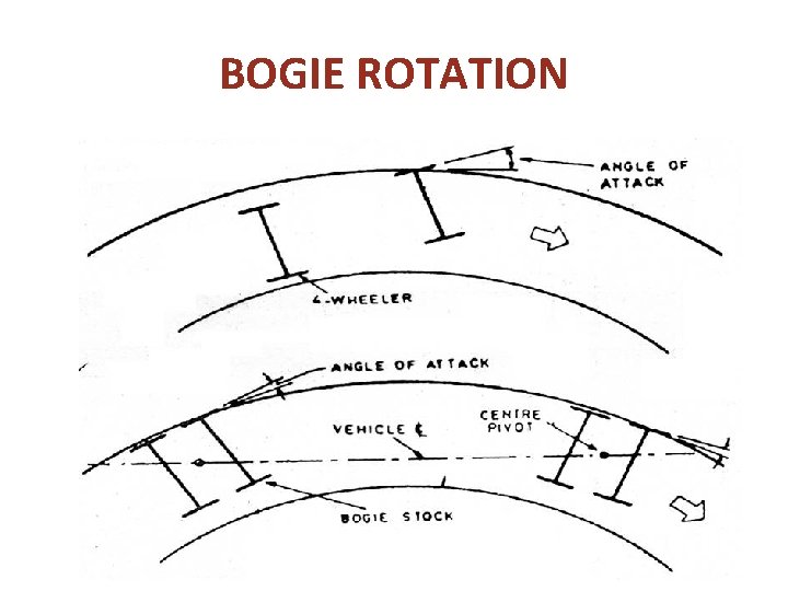
BOGIE ROTATION
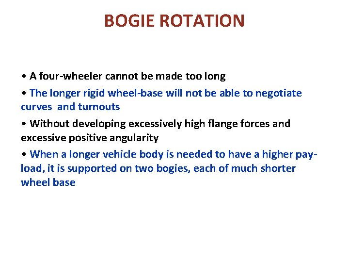
BOGIE ROTATION • A four-wheeler cannot be made too long • The longer rigid wheel-base will not be able to negotiate curves and turnouts • Without developing excessively high flange forces and excessive positive angularity • When a longer vehicle body is needed to have a higher payload, it is supported on two bogies, each of much shorter wheel base
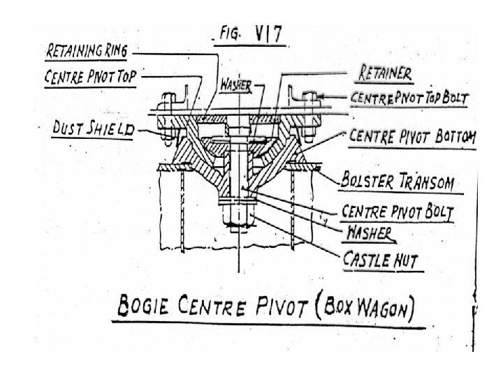
Hindrance against bogie rotation • Incase of a derailment, body surfaces taking loads be checked for any tendency towards jamming • The possible defects may be Ø Uneven wear in hemispherical pivot Ø excess wear in pivot Ø Lack of lubrication Ø Ingress of dirt
GOODS STOCK
BOGIES 8 - WHEELER WAGONS, LOADS TRANSMITTED THROUGH BOGIE TRUCK (TROLLY) CONSISTS OF SIDE FRAMES, BOLSER SUSPENSION COMPONENTS, WHEELS, AXLES AND AXLE BOXES, BRAKE GEAR ETC.
Goods Bogie • FOUR TYPES: 1. IRS FOUR WHEELED CAST STEEL BOGIE 2. IRS FOUR WHEELED DIAMOND FRAME BOGIE 3. FOUR WHEELED FABRICATED UIC TYPE (BOX TYPE) BOGIE 4. FOUR WHEELED CAST STEEL BOGIE WITH LONG TRAVEL SPRINGS AND SNUBBING DEVICE (SNUBBER)
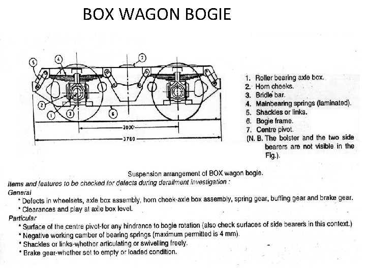
BOX WAGON • FITTED WITH 4 WHEELED FABRICATED UIC TYPE (BOX TYPE) BOGIE • DESIGNED FOR 20. 3 t AXLE LOAD • WELDED, PLATE FABRICATED BOGIE HAVING FIXED BOLSTER WITH HEMISPHERICAL CENTRE PIVOT AND PRIMARY SUSPENSION INCORPORATING 4 LAMINATED BEARING SPRINGS WITH LONG LINKS SUPPORTED BY MILD STEEL STONES
BOX WAGON BOGIE
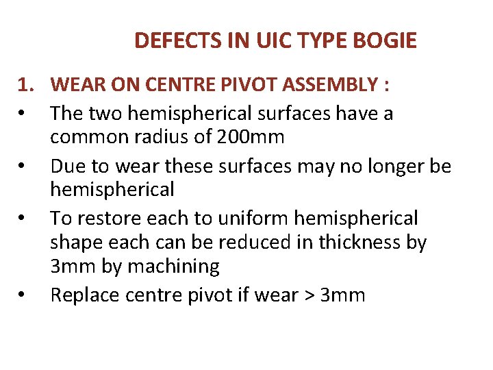
DEFECTS IN UIC TYPE BOGIE 1. WEAR ON CENTRE PIVOT ASSEMBLY : • The two hemispherical surfaces have a common radius of 200 mm • Due to wear these surfaces may no longer be hemispherical • To restore each to uniform hemispherical shape each can be reduced in thickness by 3 mm by machining • Replace centre pivot if wear > 3 mm
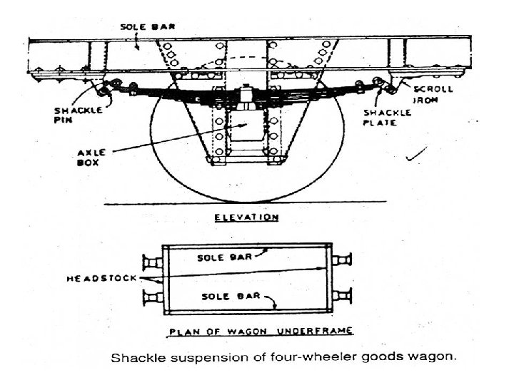
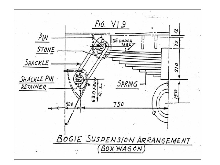
Contd… 2. SHACKLE PIN: – The Diametrical clearance between shackle pin and spring eye should not exceed 3 mm 3. SHACKLE STONE: (Fig VI 9 wagon manual) The Radii at the corners of the shackle and stone have been increased from 6 mm to 10 mm to reduce stress concentration. In no case, a stone with 6 mm radius should be used in conjunction with a shackle having 10 mm radius 4. SHACKLE : Shackles with 10 mm radius painted yellow to distinguish from shackles with 6 mm radius
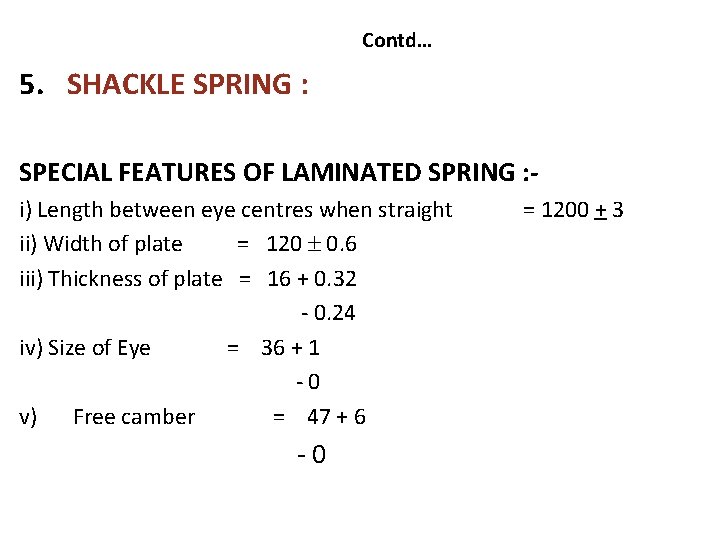
Contd… 5. SHACKLE SPRING : SPECIAL FEATURES OF LAMINATED SPRING : i) Length between eye centres when straight ii) Width of plate = 120 0. 6 iii) Thickness of plate = 16 + 0. 32 - 0. 24 iv) Size of Eye = 36 + 1 -0 v) Free camber = 47 + 6 -0 = 1200 + 3
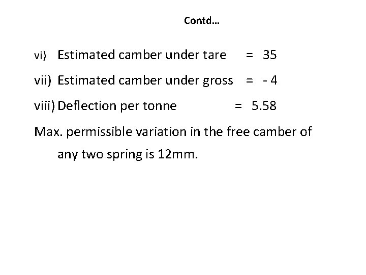
Contd… vi) Estimated camber under tare = 35 vii) Estimated camber under gross = - 4 viii) Deflection per tonne = 5. 58 Max. permissible variation in the free camber of any two spring is 12 mm.
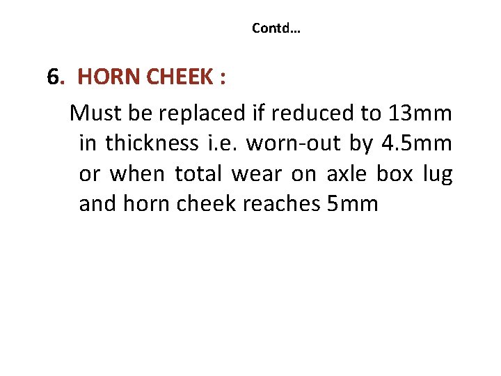
Contd… 6. HORN CHEEK : Must be replaced if reduced to 13 mm in thickness i. e. worn-out by 4. 5 mm or when total wear on axle box lug and horn cheek reaches 5 mm
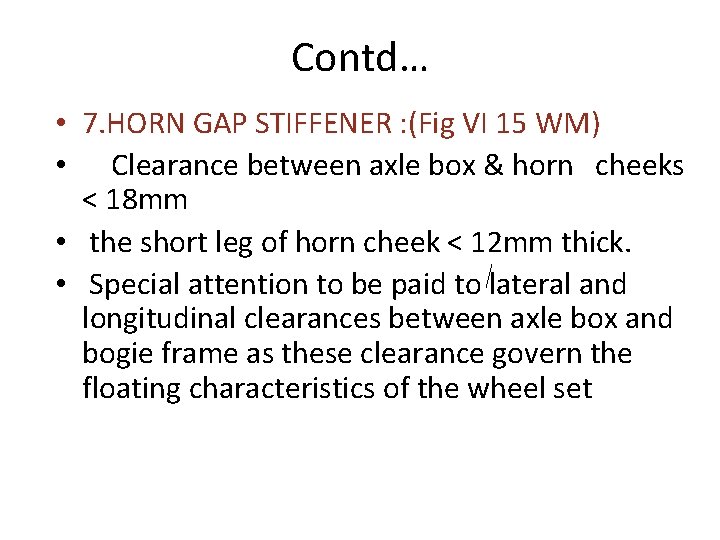
Contd… • 7. HORN GAP STIFFENER : (Fig VI 15 WM) • Clearance between axle box & horn cheeks < 18 mm • the short leg of horn cheek < 12 mm thick. • Special attention to be paid to lateral and longitudinal clearances between axle box and bogie frame as these clearance govern the floating characteristics of the wheel set
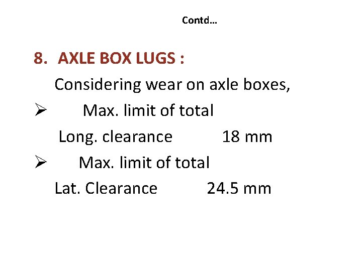
Contd… 8. AXLE BOX LUGS : Considering wear on axle boxes, Ø Max. limit of total Long. clearance 18 mm Ø Max. limit of total Lat. Clearance 24. 5 mm
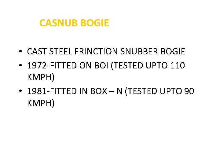
CASNUB BOGIE • CAST STEEL FRINCTION SNUBBER BOGIE • 1972 -FITTED ON BOI (TESTED UPTO 110 KMPH) • 1981 -FITTED IN BOX – N (TESTED UPTO 90 KMPH)
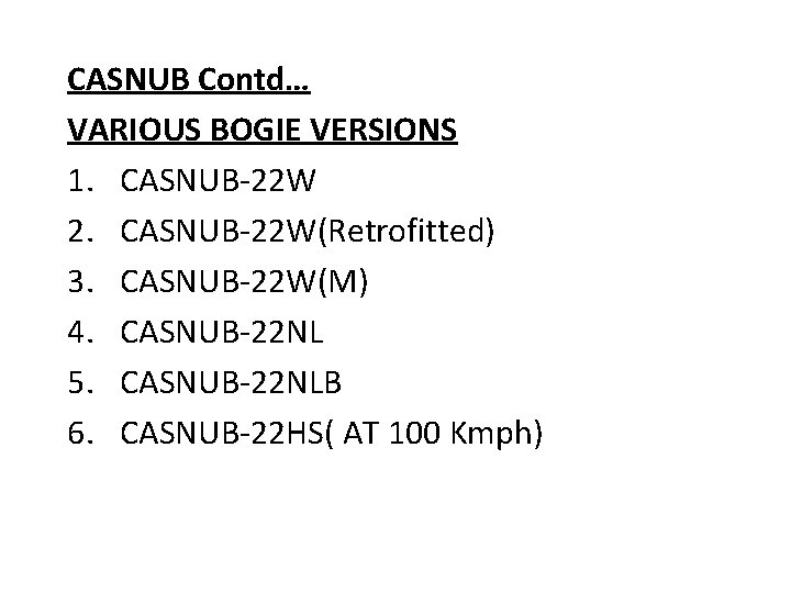
CASNUB Contd… VARIOUS BOGIE VERSIONS 1. CASNUB-22 W 2. CASNUB-22 W(Retrofitted) 3. CASNUB-22 W(M) 4. CASNUB-22 NL 5. CASNUB-22 NLB 6. CASNUB-22 HS( AT 100 Kmph)
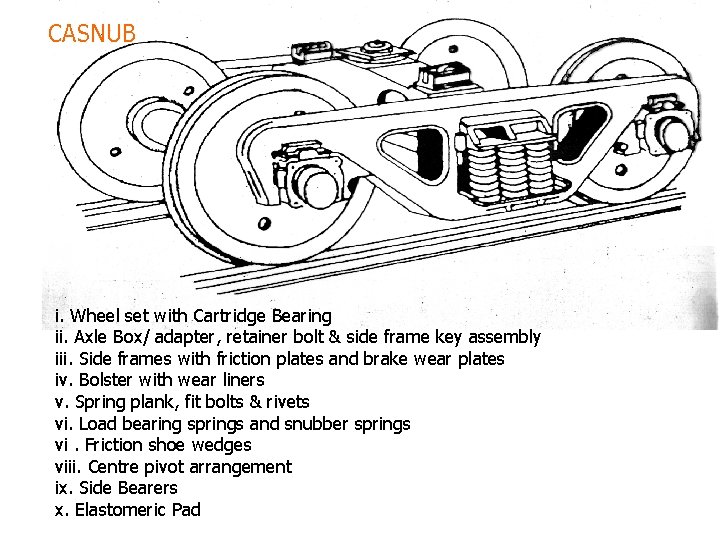
CASNUB i. Wheel set with Cartridge Bearing ii. Axle Box/ adapter, retainer bolt & side frame key assembly iii. Side frames with friction plates and brake wear plates iv. Bolster with wear liners v. Spring plank, fit bolts & rivets vi. Load bearing springs and snubber springs vi. Friction shoe wedges viii. Centre pivot arrangement ix. Side Bearers x. Elastomeric Pad
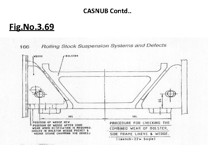
CASNUB Contd. . Fig. No. 3. 69
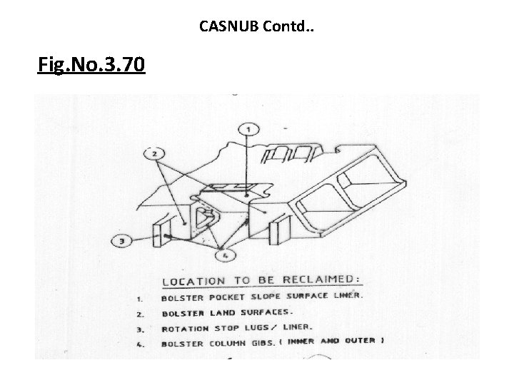
CASNUB Contd. . Fig. No. 3. 70
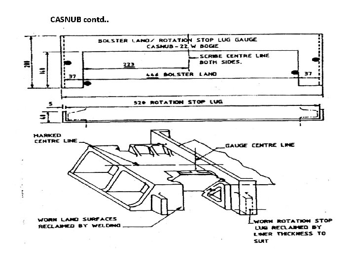
CASNUB contd. .
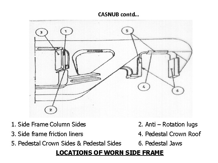
CASNUB contd… 1. Side Frame Column Sides 2. Anti – Rotation lugs 3. Side frame friction liners 4. Pedestal Crown Roof 5. Pedestal Crown Sides & Pedestal Sides 6. Pedestal Jaws LOCATIONS OF WORN SIDE FRAME
CASNUB Contd… Two cast side frames and a floating bolster • • • Bolster supported on side frames through two groups of springs which also incorporate load proportional friction damping. Side frames connected by fabricated mild steel spring plank Fitted in BOXN, BCNA, BRN, BTPGLN Wagons. Max. Population on BOX N Wagons Hunting at 90 kmph
CASNUB Contd… • CASNUB BOGIE/BOX ‘N’ WAGON • SUSPESION CHARACTERISTCS 1) The bogie suspension is at the bolster level only. 2) As there is no primary suspension system, the spring plank is subjected to bending and torsion during the wheels trying to adjust, for negotiating track twist
CASNUB Contd… 3) The cast steel-floating bolster is supported on the side frame through two nests of springs. 4) The springs contain friction snubber for oscillation control. However these snubber springs are not designed to take vertical load of the wagon 5) The positive features of these bogies are lightweight, shorter overall length, ease of maintenance, high reliability and higher capacity of payload of 22. 9 t axle load
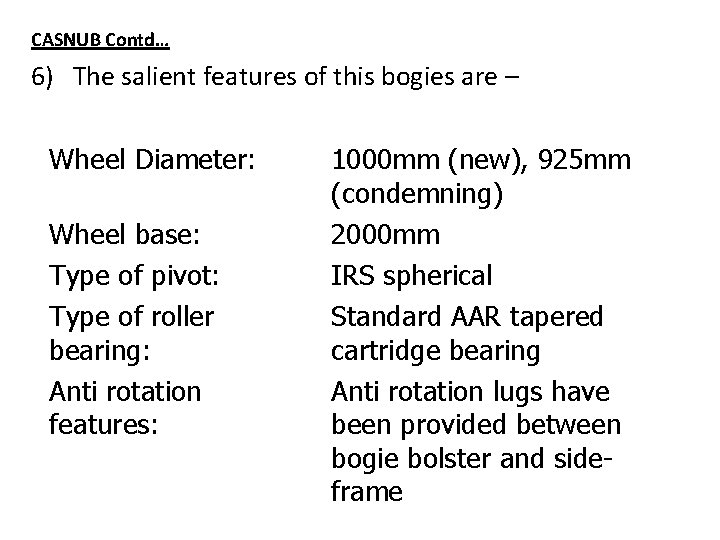
CASNUB Contd… 6) The salient features of this bogies are – Wheel Diameter: Wheel base: Type of pivot: Type of roller bearing: Anti rotation features: 1000 mm (new), 925 mm (condemning) 2000 mm IRS spherical Standard AAR tapered cartridge bearing Anti rotation lugs have been provided between bogie bolster and sideframe
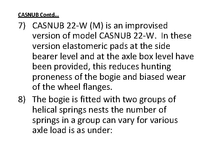
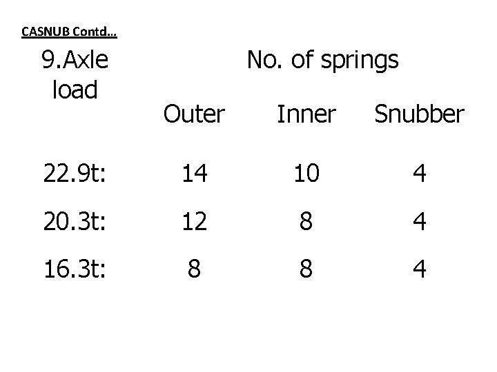
CASNUB Contd… 7) CASNUB 22 -W (M) is an improvised version of model CASNUB 22 -W. In these version elastomeric pads at the side bearer level and at the axle box level have been provided, this reduces hunting proneness of the bogie and biased wear of the wheel flanges. 8) The bogie is fitted with two groups of helical springs nests the number of springs in a group can vary for various axle load is as under:
CASNUB Contd… 9. Axle load No. of springs Outer Inner Snubber 22. 9 t: 14 10 4 20. 3 t: 12 8 4 16. 3 t: 8 8 4
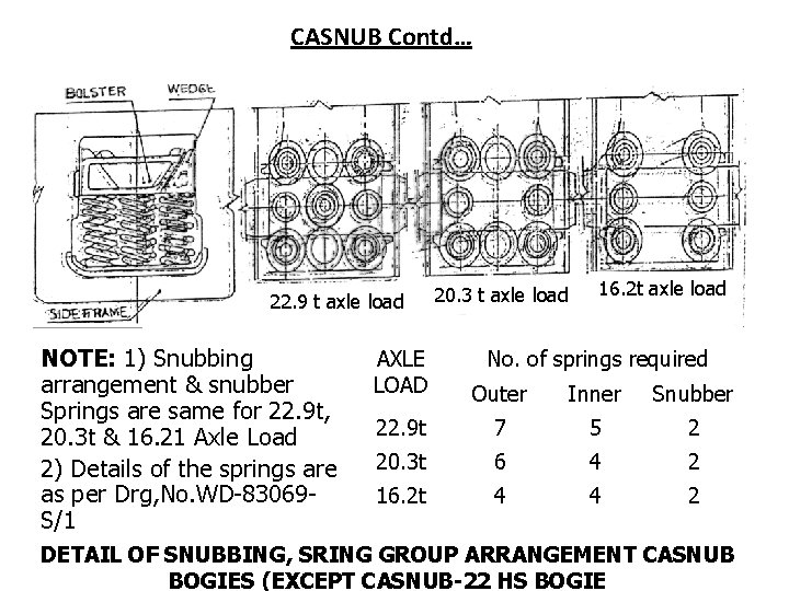
CASNUB Contd… 22. 9 t axle load NOTE: 1) Snubbing arrangement & snubber Springs are same for 22. 9 t, 20. 3 t & 16. 21 Axle Load 2) Details of the springs are as per Drg, No. WD-83069 S/1 20. 3 t axle load 16. 2 t axle load AXLE LOAD No. of springs required Outer Inner Snubber 22. 9 t 7 5 2 20. 3 t 6 4 2 16. 2 t 4 4 2 DETAIL OF SNUBBING, SRING GROUP ARRANGEMENT CASNUB BOGIES (EXCEPT CASNUB-22 HS BOGIE
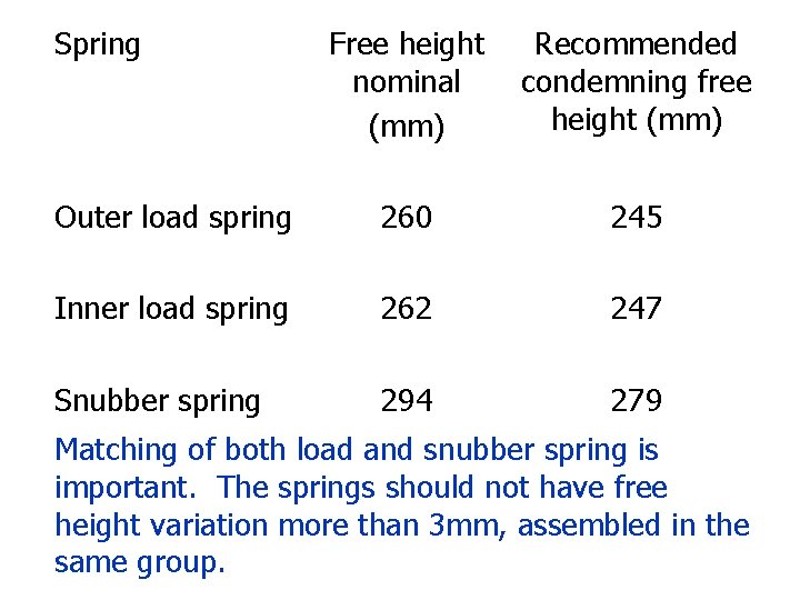
CASNUB Contd… 10)Each bogie is provided with four friction snubbers for the purpose of damping of the oscillations. These snubbers are in the form of triangular cast steel, which is supported at the snubber springs. The springs should be replaced if minimum spring height is at or less than shown below:
Spring Free height nominal (mm) Recommended condemning free height (mm) Outer load spring 260 245 Inner load spring 262 247 Snubber spring 294 279 Matching of both load and snubber spring is important. The springs should not have free height variation more than 3 mm, assembled in the same group.
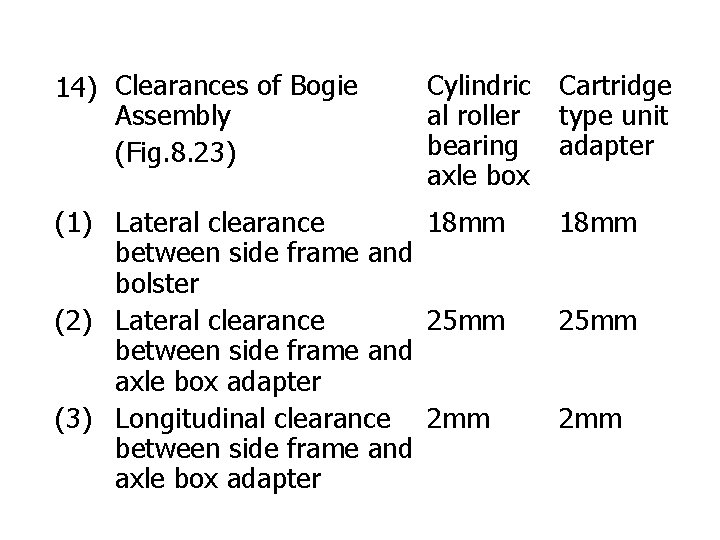
CASNUB Contd. . 11) Body weight is transferred to the bogie through IRS spherical centre pivot. Centre pivot is to be lubricated with graphite grease. 12) CASNUB 22 -W bogie is provided with a roller type side bearer, it has now been modified to constant contact metal bonded rubber pad 13) The main clearance of bogie assembly is placed as under.
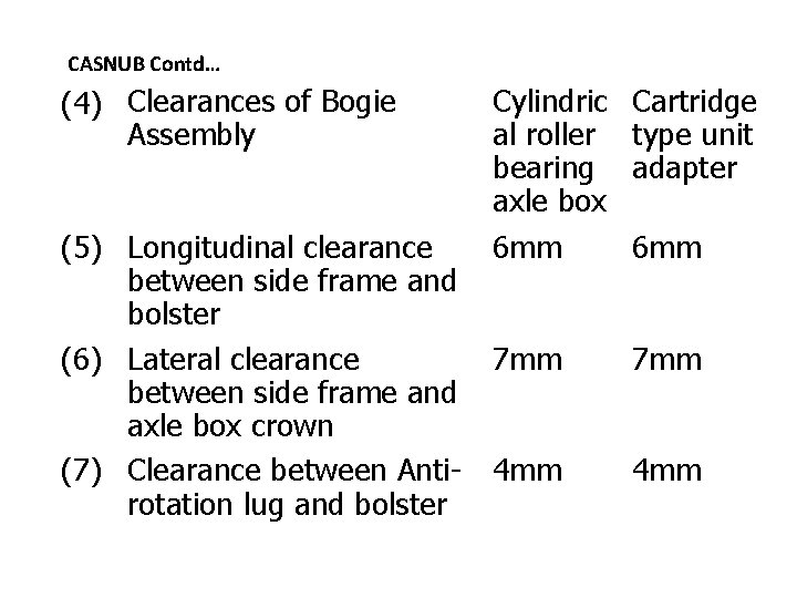
14) Clearances of Bogie Assembly (Fig. 8. 23) Cylindric al roller bearing axle box (1) Lateral clearance 18 mm between side frame and bolster (2) Lateral clearance 25 mm between side frame and axle box adapter (3) Longitudinal clearance 2 mm between side frame and axle box adapter Cartridge type unit adapter 18 mm 25 mm 2 mm
CASNUB Contd… (4) Clearances of Bogie Assembly (5) Longitudinal clearance between side frame and bolster (6) Lateral clearance between side frame and axle box crown (7) Clearance between Antirotation lug and bolster Cylindric al roller bearing axle box 6 mm Cartridge type unit adapter 7 mm 4 mm 6 mm
CASNUB Contd… 15) CASNUB bogie assembly consists of side frames, spring plank, bolster, friction shoes, load bearing spring, snubber spring, centre pivot, wheel set with roller bearings.
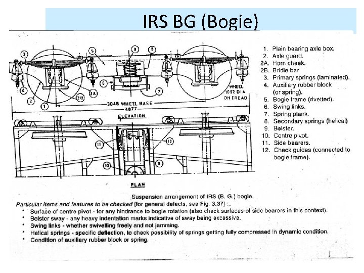
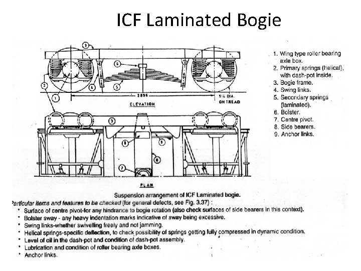
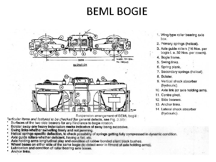
COACHING STOCK • IRS • I C F LAMINATED • BEML (BHARAT EARTH MOVERS LTD) • I C F ALL COIL
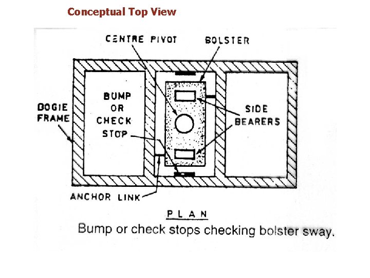
Conceptual Top View
Conceptual Isometric View
IRS BG (Bogie)
ICF Laminated Bogie
BEML BOGIE
ICF all Coil Bogie
LOCO
WHEEL FLANGE PROFILE FOR DIESEL AND ELECTRIC LOCOS – B. G. WEAR ADAPTED PROFILE
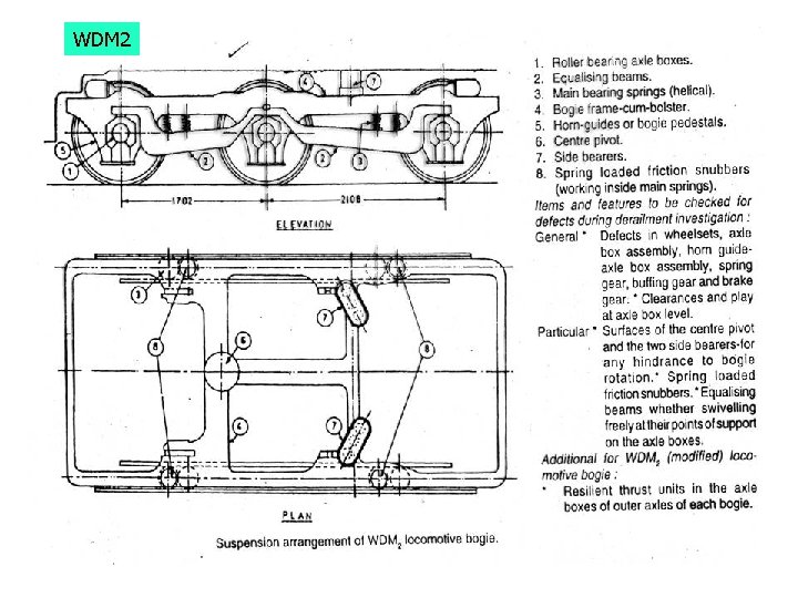
WDM 2
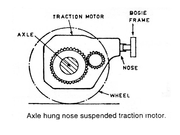
WDM 2 • Suspension Characteristics • This diesel electric locomotive with Co-Co bogies has been designed for mixed traffic service with a rated horsepower of 2600/2400 • The transmission system consists of six axle hung nose suspended traction motors, one each axle. • It has the centre Pivot and two side bearers
Contd . • The pivot carries 60% of vertical load and also transmits tractive and braking forces • The two side bearers working in oil bath carry the remaining 40% of vertical load equally distributed • It has a single stage suspension. The spring system consist of 4 groups of 2 nests of springs, each nests is helical coil spring
Contd . • The spring nests are mounted on equalizing beam, which is resting on axle box • Damping is provided by four units of spring loaded friction snubber providing damping • Wheel diameter is 1092 mm • Wheel base for bogie is 3810 mm • The snubber assembly consists of 3 alloy steel friction shoes working up and down in a case hardened sleeve
Contd . • The shoes are pressed against the sleeve by thee pre-compressed springs equally spaced vertically and radially. • A transverse play ranging from 3. 175 mm minimum to 6. 35 mm maximum is available between axle boxes and horn guides in case of outer axles
Contd . • Transverse play between the centre axle boxes and the horn guides ranges from 12. 7 mm minimum to 15. 8 mm maximum. The total longitudinal clearances in 1. 59 mm in all cases, the maximum permissible are 4. 76 mm • The suspension system has been designed in such way that all axles carry equal load
Contd . Defects • The surfaces of centre pivot as well as of the two side bearers should be checked to see if there is any tendency for causing hindrance to bogie rotation • The condition of the spring loaded friction snubber should be checked to see whether damping is adequate or not • The equalizing beams should swivel freely at their points of support on the axle boxes, otherwise off -loading of one wheel will not be shared by the adjacent wheel or wheels.
WDM 4
WDM 2 (modified) • Increased speed potential • Resilient thrust unit at the axle boxes of each bogie • Extra free float (lateral freedom) to to middle axle to negotiate sharper curves
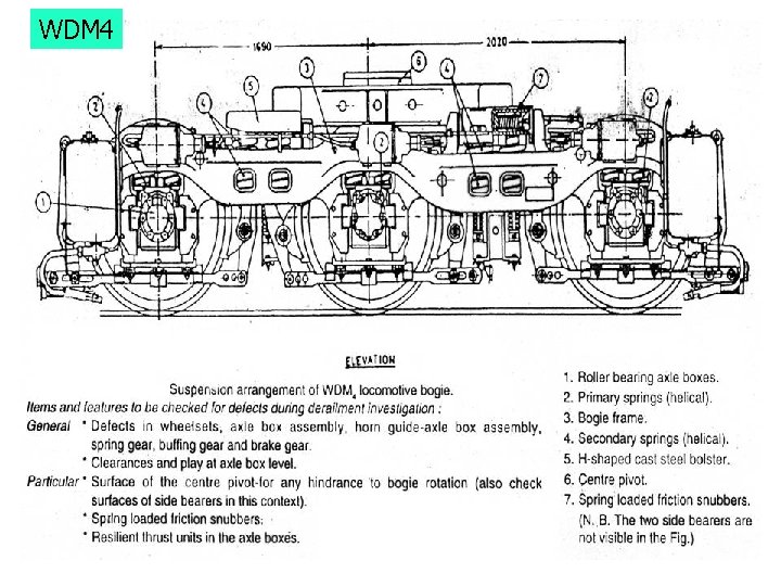
WDM 4 • Two stages of suspension, both at primary and secondary levels • Damping at secondary stage by two spring loaded friction snubbers on each bogie, no dampers at primary stage • A resilient thrust unit at journal box assembly to cushion the lateral impact
• • THANKS Take pride in what you do Love what you do Believe in what you do