RIRE Reliability Requirements and Initial Risk Estimation at

RIRE Reliability Requirements and Initial Risk Estimation at the example of the quadrupole QPS RASWG meeting - 28. 06. 2018 Miriam Blumenschein

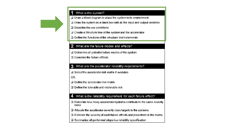
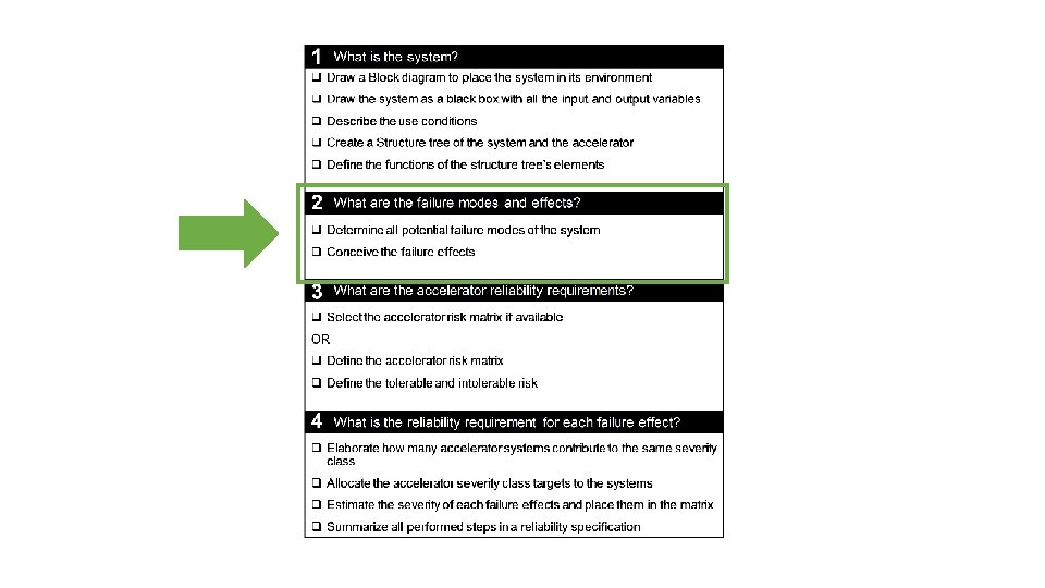
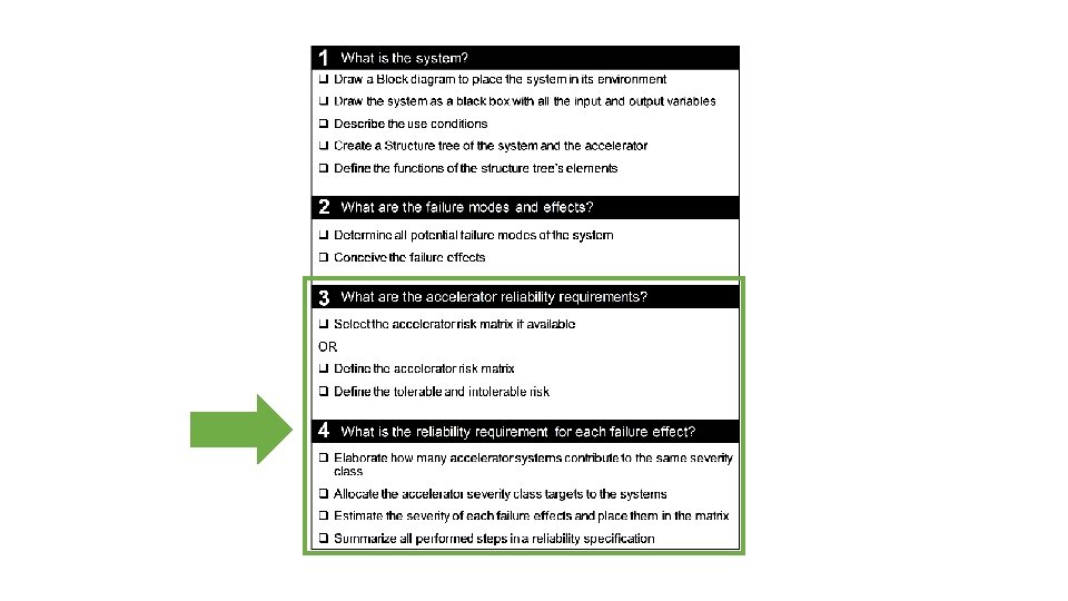
RIRE - Principle Adapted FMEA Reliability Requirements • Reliability goals • The SPS must not cause damage of the dump block more often than 1 per 100 years Initial Risk Estimation • Which system parts need to be studied further
 BIS Beam dump request")
Powering magnets and Interlock for 1 sector (out of 8) BIS Beam dump request CIRCUIT_QUENCH Even point RQF circuit Current lead Quench Interlock Loop QIL RQD circuit DQHDS 1/2 DQLPU_S open DQLPU_ B open 1/2 DQLPU_S open DQLPU_ B DQGPU-D open, read Diode MQF 1 MQD 2 MQF 47/51 Quench heater MQD 1 MQF 2 MQD 47/51 Diode MBA MBB MBC Quadrupole MQ 2 Discharge loop Quench Interlock Loop DQHDS Diode Quadrupole MQ 1 Circuit quench loop Quadrupole MQ 47/51 Odd point open, read DQHDS Upgrade in LS 2: DQLPU_B Quench Protection Quench Loop Controller DQQLC FPA Open/ Close Switch Resistor Power converter EE RQF Switch Power converter Resistor Energy Extraction System EE RQD PC_FAST_ABORT DISCHARGE_REQUEST PIC 1/2 DQLPU_S open PC_DISCHARGE_REQUEST SC equipment to be protected Beam 2 Beam 1 4

System structure: Quench Protection System Quadrupoles, one sector 1. Quench Detection QD 1. 2. 3. DYPQ Yellow Protection rack Quadrupole, n = 47/51 (one per Quadrupole) DYPB-S Yellow Protection rack type B (Dipole) S-variation, n = 54/ 55 (1 per 4 magnets) DYPG 2. Energy extraction EE, n = 1 3. Quench heater, n = 2 * 47/ 51 4. Bypass diode, n = 47/ 51 DYPQ rack, under C dipoles DYPB-S rack, under B dipoles 1. System 1. Rack 5

UPS 2 UPS 1 DYPQ MQF Interlock OUT Interlock IN Voltage tap ext_B Expert tool Voltage tap int_B Voltage tap ext_A Voltage tap int_A Reset, change configuration Win. CC supervision Logging Reset, simple commands Logging, PM DQHDS interlock QPS_OK DYPQ input and output Software link MQF + MQD DQHDS trigger DYPB-S MQD 6

• DYPQ functions Symmetric quench ~0. 5 s • Open QIL once Quench is asymmetric enough (~50 ms) • Discharge DQHDS (by DYPB-S) • Set QPS_OK to false • Send logging data • Record post mortem • HDS SI: Do not interlock • • • Keep QIL opened locally Keep DQHDS latched • Keep QIL opened locally Keep QPS_OK set to false • Keep DQHDS latched Send logging data • Keep QIL closed • Keep QPS_OK set to false Record post mortem data • Keep DQHDS • Send post mortem • Send logging data HDS SI: Do not interlock charged • HDS SI: Do not interlock Post quench I • Keep QPS_OK (trigger latched) Operator state ~ [h] set to true ~5 -10 min • Send logging data DYPQ sends Post mortem Asymmetric quench ~0. 5 s • HDS SI: Do not post mortem data analysis by MP 3 • Open QIL locally interlock ~ 15 min • Discharge DQHDS Normal Post mortem data • Set QPS_OK to false operation of QPS analysis finished • Send logging data ~4800 h/a • Record post mortem DQHDS OK: Reset detection End MP 3 decision • HDS SI: Do not interlock off/ on board/ power cycle normal acc Post quench II manually < 1 min op. signatures (trigger unlatched) Capacitor bank • Open, then close QIL locally complete Revalidation ~10 min Commissioning not OK charged (810 V) • Charge DQHDS OK • Keep QIL closed without heaters • Keep QPS_OK set to false • Keep QIL closed • Charge DQHDS Maintenance, • Depends on tests • Keep DQHDS charged • Keep QPS_OK set to • Reset post mortem buffer repair, tests • HDS SI: Do not interlock • Set QPS_OK to true false Commissioning • Send configuration • Send logging data with heaters • Depends on tests data • HDS SI: Do not interlock • Depends on tests • HDS SI: Do not interlock 7

RQD/ RQF current 900 V DQHDS voltage Δ Voltage quadrupole t. Energy extracted = 50 s t. Heater discharged = 400 ms 13 k. A t. Evaluation = 10 ms t. Loop Relay = 10 ms t. Heater effective = t. EE effective 20 ms Schematic diagram, not true to scale Symmetric or asymmetric quench: • Starts when quench is detected • Ends when heaters are discharged Post quench I: • 10 s Post mortem recording • ~ 5 min waiting to be able to send logging data t 0 = t. Q detected 100 m. V Normal operation ~4800 h/year A/S Quench ~0. 5 s Post quench I ~5 -10 min 8

• CCC function • MP 3 function 2. 1 DYPQ states and transitions Symmetric quench • Check automatically analysed post mortem data • Record results in table Post quench I (trigger latched) • Check Win. CC Asymmetric quench Operator state DYPQ sends post mortem data Post mortem data analysis finished Normal operation of QPS DQHDS off/ on manually End normal acc op. signatures complete Capacitor bank Commissioning charged (810 V) without heaters Post quench II (trigger unlatched) OK: Reset detection board/ power cycle • Communicate results to CCC MP 3 decision not OK Revalidation OK Maintenance, repair, tests • Perform tests Commissioning with heaters • Perform tests Post mortem analysis by MP 3 Reset by CCC without MP 3 agreement? • Perform tests 9

Next slide 1. Quench protection system 1. Quench Detection QD FE 1. DYPQ Yellow Protection rack Quadrupole 2. DYPB-S Yellow Protection rack type B (Dipole) S-variation 3. DYPG 2. Energy extraction EE, n = 1 3. Quench heater, n = 2 * 47/ 51 4. (Bypass diode, n = 47/ 51) 5. Circuit quench interlock 2. Quadrupole EE 3. Beam operation (beam dump, injection) 11

Qualitative severity classification for end effects Severity level Consequence 5 Catastrophic: Unsafe/ accident Serious damage of the system and its environment. System inoperable. Immediate maintenance necessary 4 Critical: Degraded unacceptable II No damage or minor damage of the system and its environment. Immediate maintenance 3 Major: Degraded unacceptable I No damage Maintenance before the next machine cycle 2 Moderate: Degraded acceptable No damage Maintenance at the next technical stop 1 Low: Availability No damage, no impact on (beam) operation Maintenance at the next technical stop if time Based on: IEC 60812, table 2 MIL-HDBK-338 B: table 7. 8 -3 Verband der Automobilindustrie (2000) VDA 3 Teil 1 Qualitätsmanagement in der Automobilindustrie – Zuverlässigkeitssicherung 12 bei Automobilherstellern und Lieferanten – Zuverlässigkeitsmanagement. 3. Aufl, Frankfurt

Excerpt of the FMEA report 13

DYPQ failure effects = failure modes of quadrupole and beam operation 1. Quench protection system 1. Quench Detection QD 1. DYPQ Yellow Protection rack Quadrupole 2. Quadrupole • • DYPQ_EE 1: False heating, S 3 DYPQ_EE 2: Quadrupole damaged, S 5 3. Beam operation (beam dump, injection) • • DYPQ_EE 3: Injection delayed, S 3 DYPQ_EE 4: False beam dump, S 3 DYPQ_EE 5: Missed beam dump by DYPQ, beam dump by another protection system, S 4 DYPQ_EE 6: Missed beam dump, S 5 14

To be discussed !!!! Consequences Downtime Frequency Very frequent 1/day Frequent 1/week Probable 1/month Occasional 1/year Remote 1/ 10 year Improbable 1/100 years Not credible 1/1000 years Catastrophic Critical Major Moderate Low 3 month 3 weeks 3 days 3 hours 3 mins Quadrupole • • DYPQ_EE 1: False heating, S 3 DYPQ_EE 2: Quadrupole damaged, S 5 DYPQ_EE 1, EE 3, EE 4, DYPQ_EE 5 DYPQ_EE 2 DYPQ_EE 6 Beam operation (beam dump, injection) • • DYPQ_EE 3: Injection delayed, S 3 DYPQ_EE 4: False beam dump, S 3 DYPQ_EE 5: Missed beam dump by DYPQ, beam dump by another protection system, S 4 DYPQ_EE 6: Missed beam dump, S 5 16

17

18

Risk estimation: what needs to be studied further? FM which are in category 4, 5 or undetectable Detailed study of the trigger link 19

Next steps: extend the fault tree sideward and downward 1. Quench Detection QD 1. DYPQ Yellow Protection rack Quadrupole, n = 47/51 (one per Quadrupole) 1. DQLPU-B Local Protection Unit type B (i. QPS) n = 1 1. DQQDL Quench Detection Local, n = 4 (2 focusing, 2 defocusing) 2. DQAMC Acquisition and Monitoring Controller, n = 1 3. DQCSU Controller and Supervision Unit, n=1 2. DQHDS Heaters Discharge power Supply, n = 2 3. DQLIM, n = 1 2. DYPB-S Yellow Protection rack type B (Dipole) S-variation, n = 54/ 55 (1 per 4 magnets) 1. 2. 3. 4. 5. 3. DQLPU-S Local Protection Unit type S (n. QPS), n = 1 1. DQQDS Quench Detector Symmetric, n = 4 2. DQQBS Bus – bar Splice detector, n = 5 3. DQQDE Quench Detector voltage to Earth, n = 3 4. DQAMGS Acquisition and Monitoring crate controller G S, n = 1 DQLPU-A Local Protection Unit type A (asymmetric quenches on dipoles) DQLIM Local protection Interface module (PS for DQLPU-A), n=1 Power Pack for DQLPUS, n = 2 DQHDS Heaters Discharge power Supply (Dipole), n = 4 DYPQ rack, under C dipoles DYPB-S rack, under B dipoles DYPG 1. DQGPU-D Global Protection Unit type D, crate 1. DQQDC Quench Detector Current leads, n = 4 2. DQQDB Quench Detector main Busbar, n= 2 3. DQAMG Acquisition and Monitoring crate controller, n = 1 2. Energy extraction EE, n = 1 3. Quench heater, n = 2 * 47/ 51 4. Bypass diode, n = 47/ 51 1. System 1. Rack 1. Crate 1. Board 20

Conclusions • RIRE provides a framework for the experience based derivation of quantitative reliability targets: system reliability requirements are derived from accelerator requirement • RIRE shows the risks posed by a system • RIRE prioritizes subsequent, more detailed analyses • RIRE works for systems with context dependant functions • System failures are visualised as Fault Tree model which can be extended sideward (more systems) and downwards (more details)

Thank you for your attention 22

Environment variables 2. 1 DYPQ states and transitions Beam: false RQD/ RQF energy: false or true Beam: false or true RQD/ RQF energy: false or true Transition Symmetric quench in quadrupole Initiator Post quench I (trigger latched) Operator state Send post mortem data Asymmetric quench in quadrupole Post mortem analysis by MP 3 Post mortem data analysis finished Normal operation of QPS DQHDS switched off/ on manually Commissioning without heaters OK: Reset detection board/ power cycle Capacitor bank charged (810 V) Post quench II (trigger unlatched) Commissioning with heaters MP 3 decision not OK Revalidation OK Maintenance, repair, tests 23

DQLPR 1 3 UPS 2 DQLPR 2 Voltage tap ext_B Voltage tap int_B Interlock OUT Interlock IN Voltage tap ext_A DQQDL RQF+D B Trigger supply coupling on motherboard 3 DQCSU U(I) Trigger coupling on motherboard UPS 1 UPS 2 Power Pack A Power Pack B DQQDS A DQQDS B Trigger coupling on motherboard Burndy board Power supply Supervision DQCLT 2 U(U) DQHDS 1 DQHDS 2 MQF Trigger line DQHDS 1 DQHDS DQCLT 1 Voltage tap int_A Information DQAMC DQHDS Quench heater DQLPU-B UPS 1 DQLIM DQHDS interlock QPS_OK DQHDS 1/2 DQLPU_S DQLPU_ B 1. Block diagram: Details DYPQ rack DYPB-S MQD DYPQ Trigger line DQHDS 2 Trigger line DQHDS 1+2 QPS_OK 24

The baseline system failure rate estimated with 217 Plus is 5700 FIT which corresponds to an MTTF of 0. 0001754 Ghrs or 36. 54 LHC operation years. 25

26

27

Component failure probabilities • 28

Cut set and system probabilities • 29

Cut set and system probabilities • Calculated with Isograph 30

Results – top event The probability that for one out of 392 quadrupoles no (0 oo 2) heater is fired within 100 years is 0. 1 %. 31

Results – Cut set importance • 32
- Slides: 32